 spencer
So, with breadboard and jumper wires, I had proved that a Pi Zero would be great as a keyboard / display adapter for the RC2014, but now I needed a neater and more permanent solution. Time to fire up Kicad...
On the face of it, there really isn't much to this. It's just a passive adapter between the Pi Zero and the RC2014 with a composite signal breakout. The Kicad library, however, didn't know what a Pi Zero was (or even a phono connector). I found some other Pi variants on line, but although the 40 pin header is the same, they didn't contain the extra 4 pins (reset and comp out), so I quickely drew up some new components
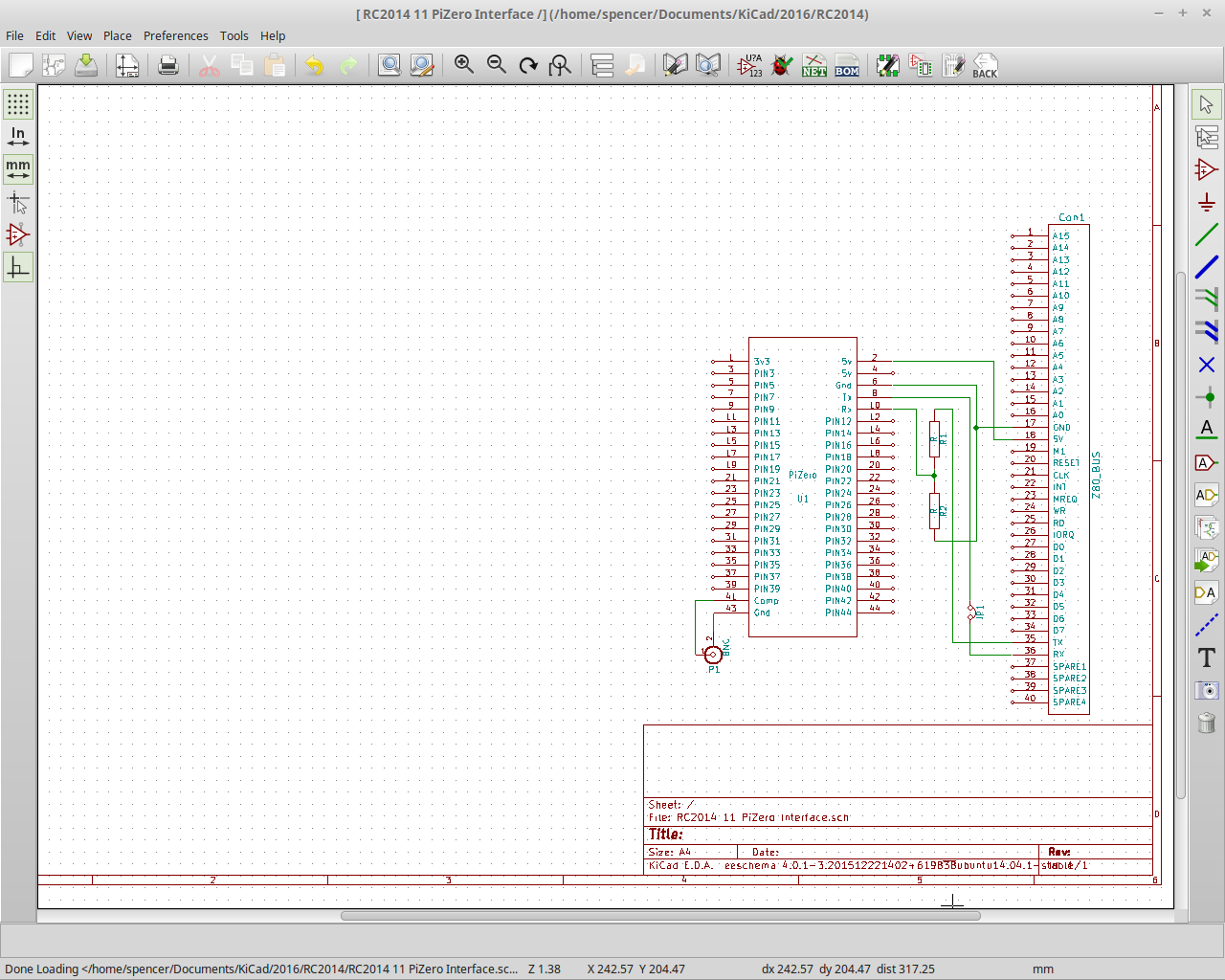
See, I told you it wasn't complicated! 5v power and ground go to the RC2014 header. Tx from the Pi goes via a jumper to Rx on the RC2014 (in case I want to add some other form of input at a later date) and Tx on the RC2014 goes via a voltage divider to Rx on the Pi. Then the ground and signal go out from the Pi to a connector for the composite out. Simples!
The PCB isn't much more complicated, although, again, I had to design new components for the Pi and also for the BNC adapter
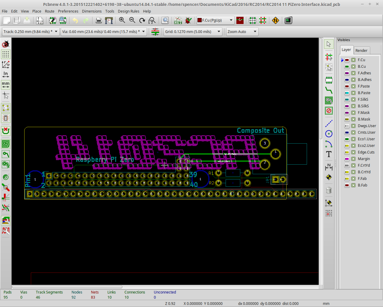
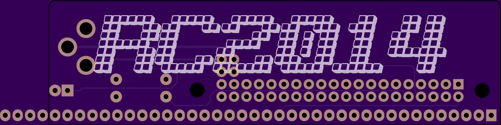
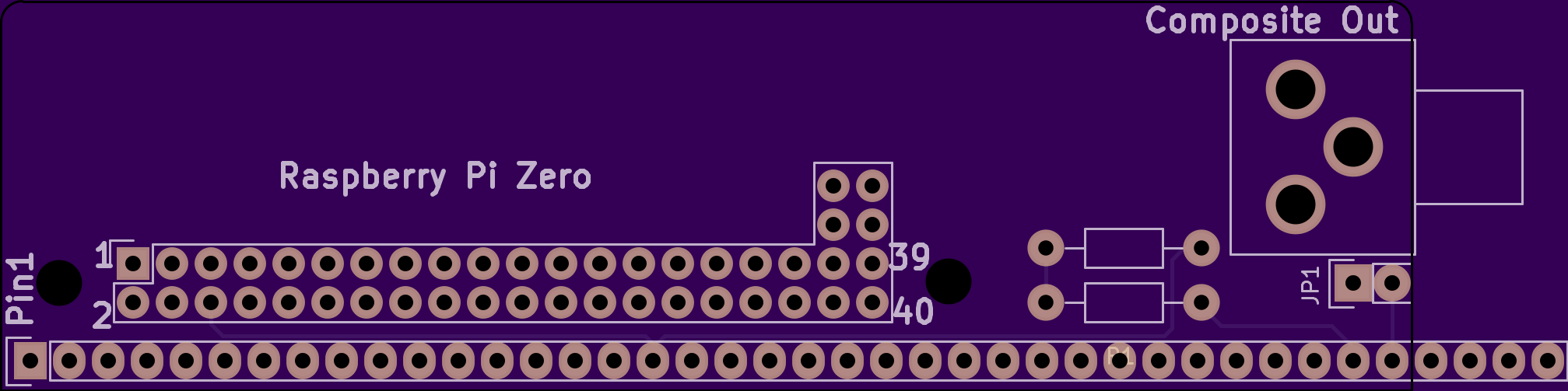
For this board, I decided to get fancy and round off the corners! And also add some mounting holes that line up with the holes in the Pi Zero in case I want to bolt it to the board.
Once I was happy everything would turn out the way I wanted, off to OSHPark I went!
Then the waiting started...
Discussions
Become a Hackaday.io Member
Create an account to leave a comment. Already have an account? Log In.