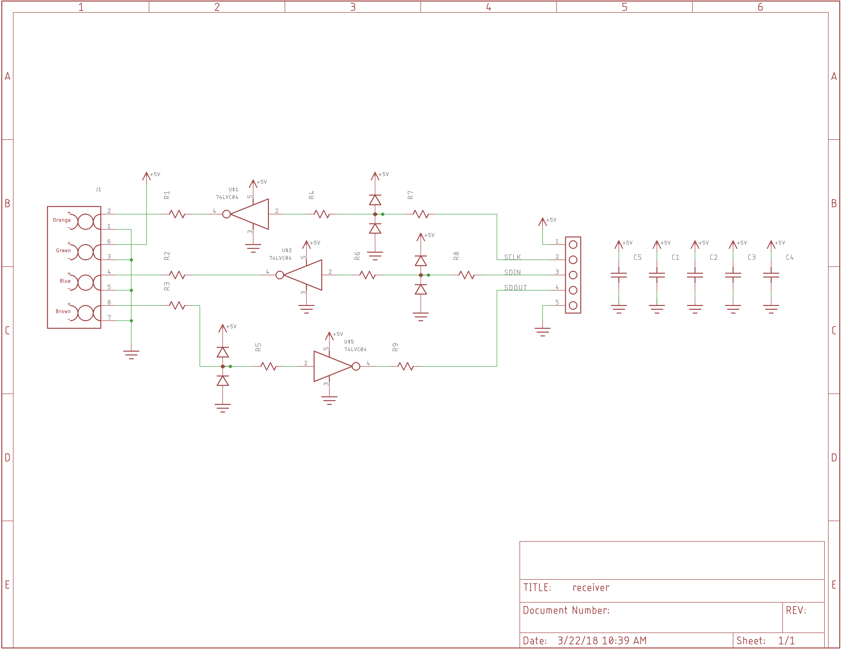
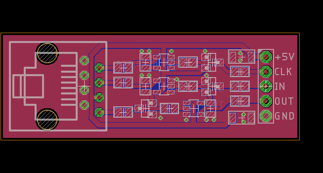
I was originally going to integrate the MCU, stepper drive, and everything else on one PCB, but I decided to go modular, so I can just wire up some existing boards for a prototype. The missing piece was a driver and receiver for the MCU end of the cable, so I threw together a little PCB for it.

It uses 74LVC1G04's as cable drivers and receivers, with added parts for ESD protection. The connection to the sensor head is over a cheap ethernet cable. The PCB was really straightforward to route.

I wish they were all this easy.
Now that I sent it out, I regret not adding mounting holes. Oh, well, it costs less this way.
I also should have routed the 5V line around the ground pins on the RG45 connector instead of between them, considering the signal return paths. There's a ground plane underneath, but it would probably help to keep the top plane unbroken there.
 Ted Yapo
Discussions
Become a Hackaday.io Member
Create an account to leave a comment. Already have an account? Log In.