 Michael O'Brien
So, as I'm about to pass out I've completed and uploaded the following PCBs:
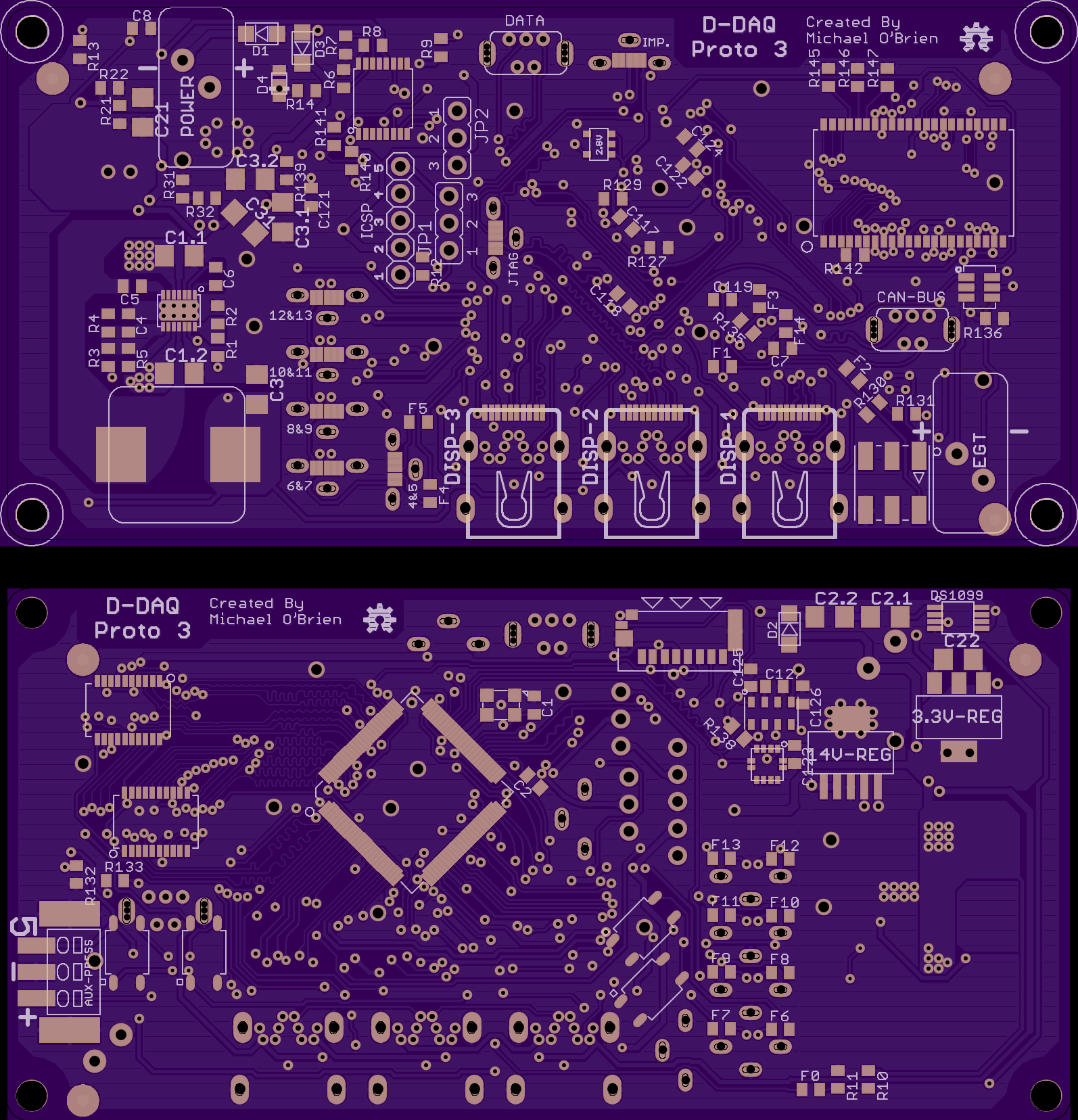
- D-DAQ's Mainboard, Prototype 3 - The prototype number has been bumped to 3 because I've reworked the power supply subsystem and have added a 3.3V, 32.768 kHz charge pump to the 14V Rail. I've also lowered it's output voltage to ~13.7 V to allow it to behave a bit better in case there is any sag on the battery. The LDO has been replaced with a more thermally efficient version and though it also has more copper exposed, some of it is covered so it's performance characteristics are unknown. There are numerous footprint and silkscreen tweaks across the board. I'm testing a 603-SMD-footprint-on-a-diet too.
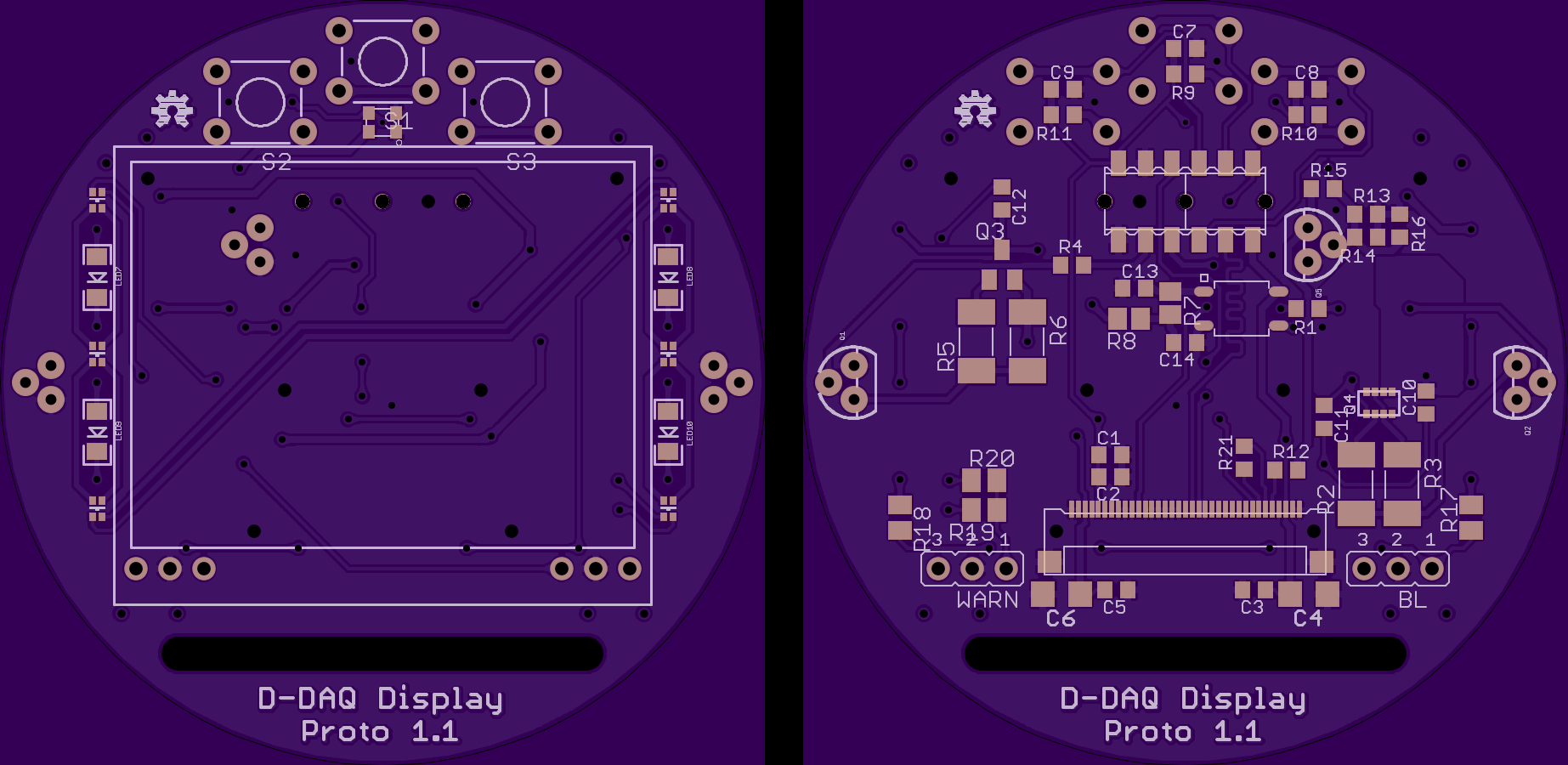
- Display Board - I've tweaked it a touch to allow what I have mentioned, jumpers to enable/disable the accent lights and warning lights separately. Fixed the text alignment too. I had to finish the adapter boards before ordering this one
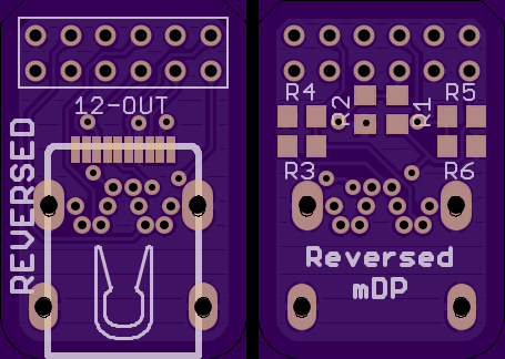
- mDP Reversed Adapter - From a previous log last week I noted how the reversed adapter screwed over the pinout on the mainboard. This was fixed, but also required an adapter board. This one is for the Reversed receptacle.
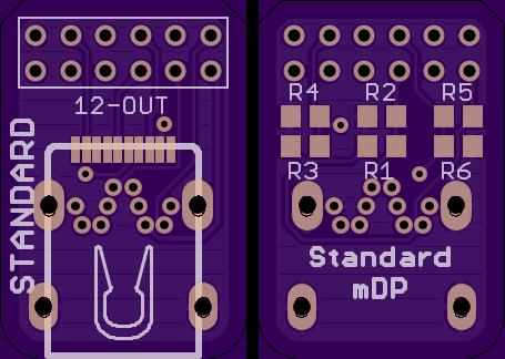
- mDP Standard Adapter - This is an adapter for the standard pinout. This board and the other are required because a mDP cable doesn't have enough flex to make a 90˚ bend in side 2.25" dia. and also clear components.
The adapter boards use a 12-pin, right-angle header to perpendicularly plug into the Display Board. As long as a standard adapter is used with a mainboard that used a standard receptacle or reversed with reversed, you're good to go. This board also allows the Display Board's receiving pinout to stay constant and the terminations for the data lines and high(er) speed PWM line are on this adapter board.
For both of these little boards, I opted to try out freerouting.net to see how it's behave and if it'd be a bit useful. It allowed me to focus on other work while it hacked away at these guys. I did have to tweak a couple things on both after importing back into Eagle, but I'm happy with the work it did. I'm having it chug away at the mainboard to see if it can help out there at all. I'm fully aware though that it does no optimizations for maintaining contiguous ground planes so for some things it's use may be limited. I do want to see if it can remove several 10's of vias to reduce fabrication time and cost.
Anyhow, screen shot time:
Edit: Boards were ordered this morning and were scheduled to be panelized on Monday, however Osh Park panelized them and sent them in today. I'm far from being out of the tick of it. Right now, with those boards in the fab shop, and some modicum of confidence as to their functionality, I'm going to get started on the sensor board. Right now I have 10 planned and 3 test boards planned. Remember that the sensor boards have 2 inputs on them.
So far the boards that are planned are:
- 5V sensor to 3.3V - I'll be taking the op amp route.
- Dual EGT
- Dual Pressure - Using the same 100 PSI sensors most likely.
- Dual RTD tap - These will be interesting
- Pressure & EGT
- PWM to 3.3V - Not sure how I'll be doing them. an RC circuit is frequency specific. A small micro with a bit of code may be a better choice.
- RPM & Lift Needle - I'll be needing some fancy electronics for the latter
- RPM & Speed
- Pressure & RTD
- EGT & RTD
Overall this shouldn't be too "difficult" as once I have a circuit confirmed as solid and reliable, it's only a matter of getting in on a board next to another. If someone has any requests for different types of sensor inputs, I'm more than open to hear about them :)
Discussions
Become a Hackaday.io Member
Create an account to leave a comment. Already have an account? Log In.