 Michael O'Brien
Here is where I'm currently at with version 4 of the prototype:
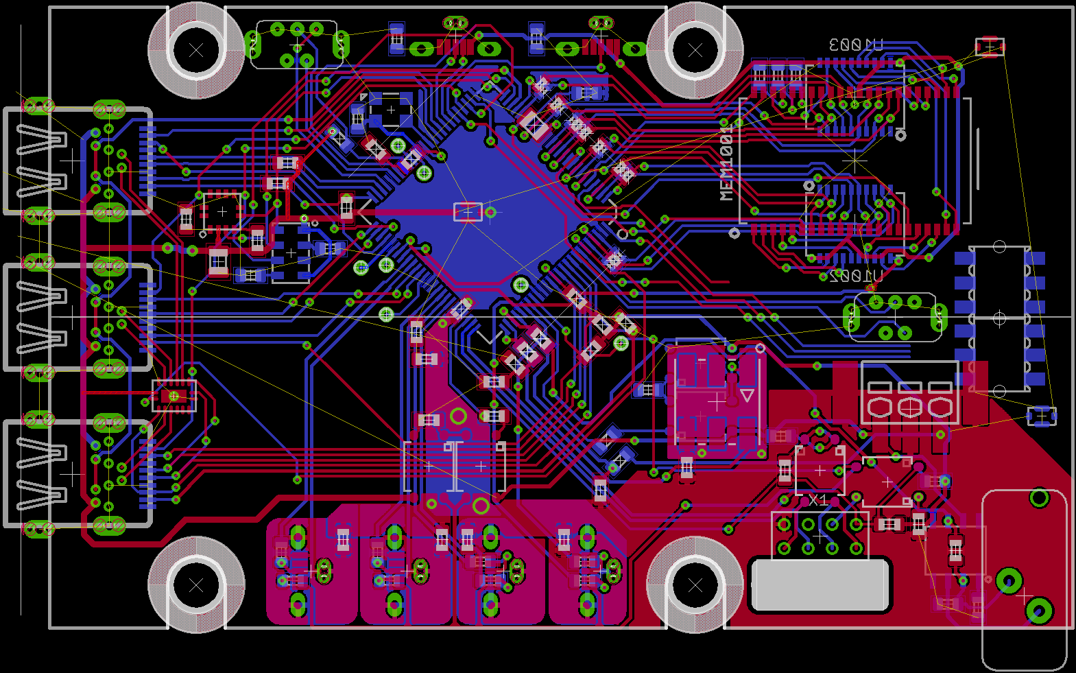
Thick border is the flat top area on the case. The 4 keepout areas are portioned for grommets for helping shock absorption to the PCB directly. To avoid a large empty mass of PCB, and to position the SD card in a cleaner spot on the other end of the case, the SD card will be on a small-ish daughter board connected via the same pair of right angle interconnects used for the Display Board adapters. The PCB will also help as a guide to allow clean insertion of the card. Mainboard PCB cost from OSHPark is down about $4 too. When I has the time I'll adjust the vias, if I can, so I can accommodate SeeedStudio's PSB fabrication service as they require much larger annular rings.
The to-do list encompasses a few pin points on the board similar to that of the JTAG adapters to connect power to the board, creation of the power supply daughter board (should be a relatively simply copy and paste), ensuring a solid op amp layout for the thermocouple, running the card detect and write protect pins for the SD card, and finalizing the pinout on the 12-pin adapter for the SD card daughter board.
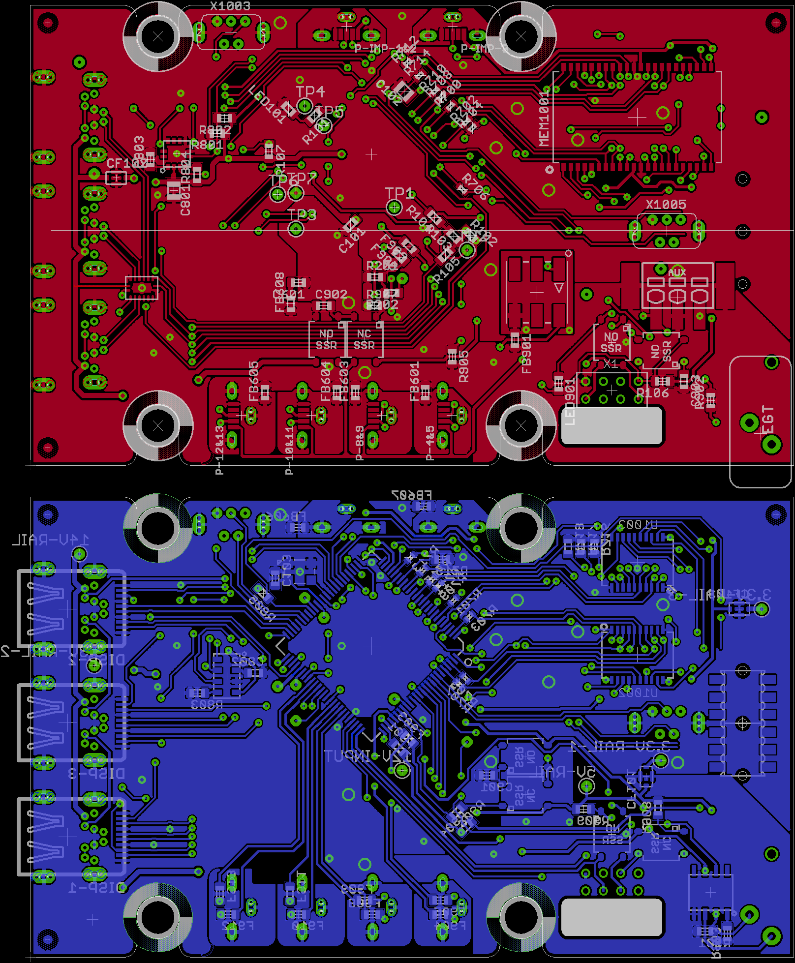
Update
SD card is the only thing left. It'll be a variant of the 8 pin connector used for the uUSB-B slot in the bottom right It is so much cleaner than before. Still have some artwork to add...
Discussions
Become a Hackaday.io Member
Create an account to leave a comment. Already have an account? Log In.