 Michael O'Brien
Whether I use an SEPS525-based display or a SSD1353-based display, there is a pin on both controllers called I-ref. This is an internal current reference for brightness control. Its nice that the SSD1353 data sheet gives a transfer function for how to use this resistor, larger values decreases brightness, but the SEPS525's sheet, albeit from the controller datasheet of a display model datasheet, has no reference of it's own.
That being said, I have long since planned using this pin to control display brightness. I knew I wouldn't have a control line from the mainboard to each display that I could use to flip a switch and dim the display. Also, that kind of digital interface usually has by nature or is created with a delay in response time of several seconds, which is something I personally despise. I could also go with running a trigger wire from headlight activation for dimming the displays, but it's so much less elegant and "dumb" in comparison. Anyone who'd driven knows that light doesn't hit the interior of a car in a uniform fashion and that is why individual, fast response of the display brightness matters to the design.
In conjunction with not knowing if the resistance is proportional, inversely proportional, logarithmic, or exponentially related to display brightness, I cannot predict when and by how much the display will dim or brighten. So, upon realizing this nearly a year ago, I knew I had to find a way to create an analog roll-off of the brightness with a simple circuit. After a few days of research, I settled on the APDS-9007.
This little guy has a current output from 5 uA to ~46 uA and by nature of the load resistor, turns that into a voltage for an ADC. Dedicating 3 ADCs is overly complicated so as I'm working on the display boards, a discrete solution needed to be found. After a little bit of research, I learned that BJTs don't mind such low current drives to their bases so all I had to do was figure out a good way to bias it properly. Oh, and since I don't know if an increase or a decrease in I-ref will dim the display, I need the circuit to do both.
Well, I decided it would be overly complicated to have both an NPN and PNP resistor on the PCB along with 2 jumpers and 2 possibly used or unused resistors, so I setup the circuit to just include or exclude the biasing resistors for one transistor. This is equivalent to removing or including 2 parallel resistors on board so it takes up the space of only 2 extra resistors. Here is the circuit:
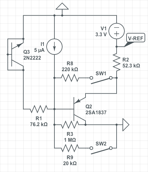
You can ignore the defunct BJT in the upper left. It's there so I do not have to delete and add the transistors over and over for simulation testing. The constant current source, I1, is simulated with the weep or 5 uA to 45 uA and the switched behave as 'jumpers' to where I can simply remove them in real life as I mentioned above. R1 is the load resistor on the light sensor. I'm also making a huge assumption about the reference voltage being 3.3 V inside the SEPS525. It could be 14 V or it can be a self-generated reference voltage. Either way, this circuit should give me an idea of the response range and type, linear or logarithmic or exponential, so I can add it into the final design.
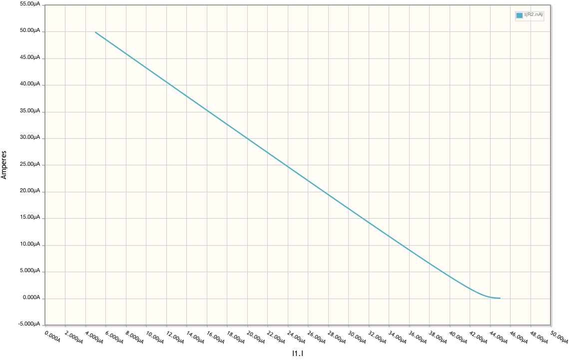
The responses are as follows. I wish I could have made the ramp up more linear, but it'll suffice. I'm also making an assumption on the SEPS525 based on the SSD1353: There is a limit to the maximum current that I-ref should be. I can overshoot that max a little, but since the initial testing will be indoors, so it's easy to control the lighting and figure out some semblance of a response curve.
Ramp Down response:
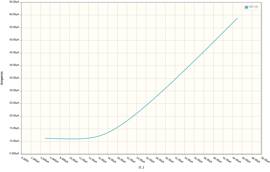
 Ramp Up response:
Discussions
Become a Hackaday.io Member
Create an account to leave a comment. Already have an account? Log In.