 Michael O'Brien
Change log to the design files
Edit: Parts list reflects v3.5 changes. Link to screen shot of expanded board space.
- Fixed MLP3115 pinout and adjusted footprint for slightly easier soldering
- Fixed MAX4239 SOP-8 footprint
- Removed ICSP header
- Removed associated manual jumpers and pin headers.
- Accelerometer and Ambi. Temp. & Barometer have been relocated due to freed room from bulky pin headers
- roughly centered and reoriented 14 V LDO. Now has a about 3x the amount of copper surrounding it.
- Changed AN pair 6&7 to a flat/right angle uUSB Type A port for reasons stated below and clearances. I've adjusted the maximum sheath clearance of the plugs from 0.25" to 0.28" per plug. Literally spreading things out more than 0.5" on a 5 cm high board with little deficit.
- Added an additional NO and NC, Form-A and Form-B, relays to toggle the power pin on uUSB port for AN input pair 6&7. This pin is now toggled between USB-PWR and MCLR. By using a uUSB type A adapter, the board can be programed via ICSP. Will need to make an adapter and board needs power from a source other than the programmer.
- Changed JTAG to a static, 4-pin pin header. Will need to make an adapter to program. via a "standard" 14-pin cable on a simple breakout board. PTC fuses are 470 ohm and now serve as rudimentary input protection where as v3.4 had none.
You can grab the individual files or a zip of them all from my GitHub account. When I have the chance, I will add up a library for the components and modifications to them, but Eagle does make this an easy task.
I still need to order more parts for the Display Board and stuff some adapter boards. Due to shot stopper problems that have now been fixed in the design, I will not be able to test ambient temperature and pressure or EGTs. I'm considering adjusting the SRAM's footprint and the octal D-latches to allow more pad to show as the pins stick over and I'm using the manufacturer's suggested footprint, which is usually generous, no?
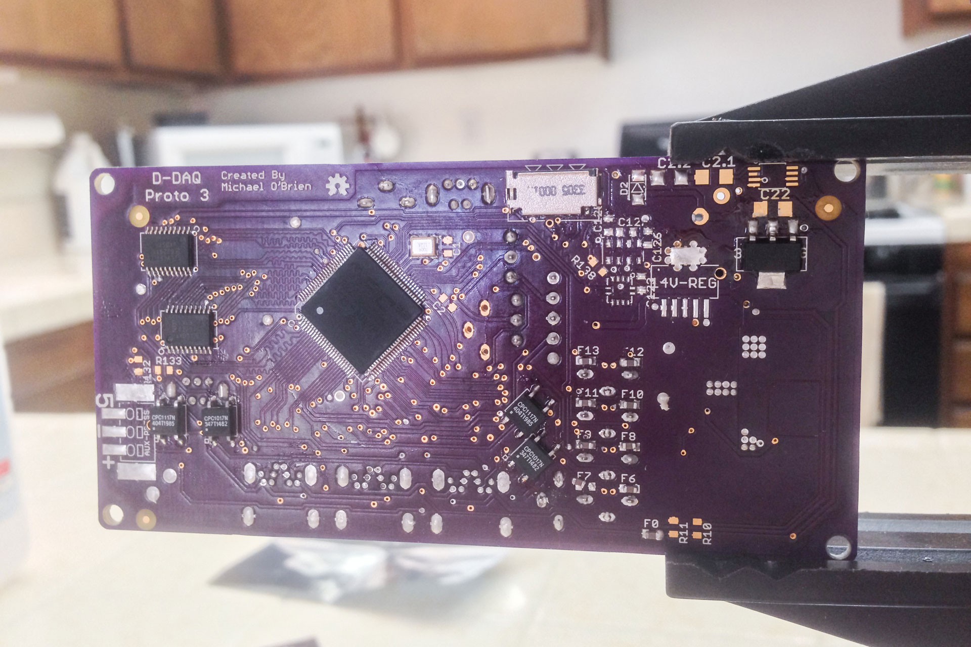
Aside from spending the day on that, I stuffed the QFN SMPS regulator, 5V LDO, PIC32MX795, SRAM, latches, I2C-to-SPI IC, primary oscillator and associated LDO, my SSRs and the uSD card slot. Ended up bending 2 pins on the uC by snagging them with the braid while removing solder bridges, but they didn't break, there is no contact with neighboring pins, and there is no solder bridge. This endeavor was aided by a USB microscope.

My Pickit 3 should arrive with my parts on Saturday so I can finish stuffing the board. A few days behind my planned deadline, but not too far off. Unless there is something I missed, this board is complete enough to do the majority of testing I need, though I'll have to make some hard decisions on where or not to order up v3.5 of the prototype or wait until or if I do a redesign for a daughter board power supply subsystem.
I'm still looking at JTAG interfaces. The Flyswatter2. I'm going to be doing pretty quick timing in hardware so getting close to the 40 MHz max JTAG clock on the PIC32 is desired. ICSP is only up to 10 MHz for programming. Either way, work continues and it's time for sleep.
Discussions
Become a Hackaday.io Member
Create an account to leave a comment. Already have an account? Log In.