 shlonkin
-
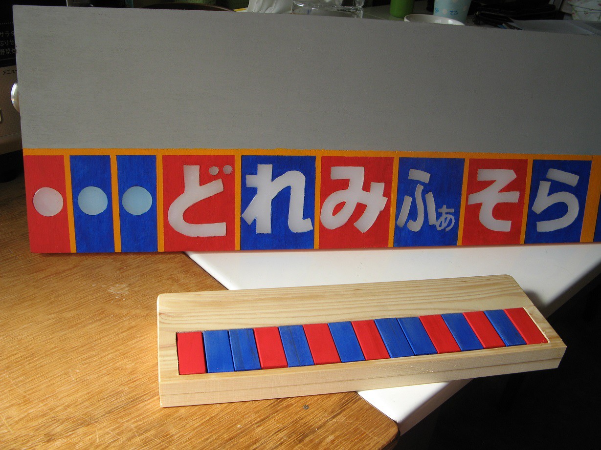
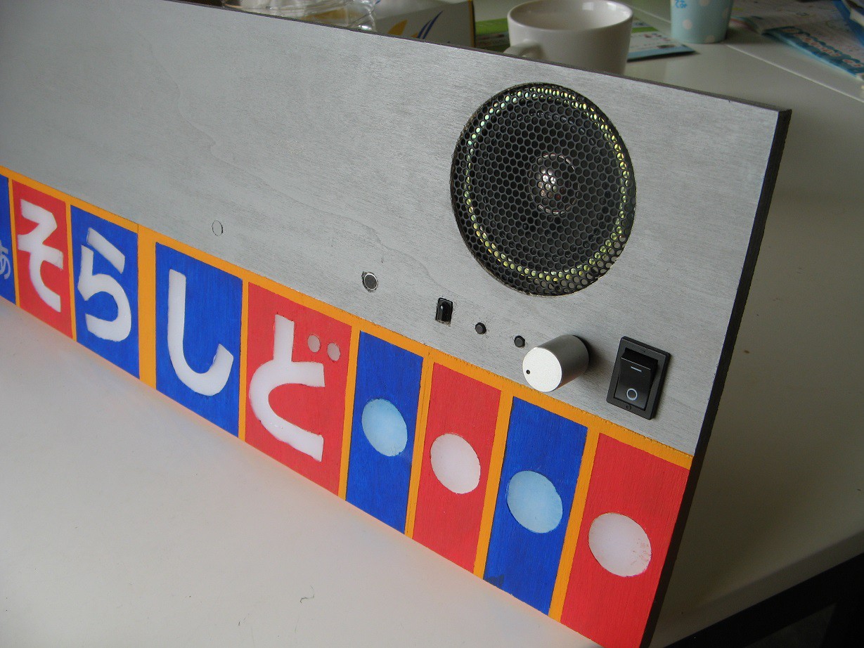
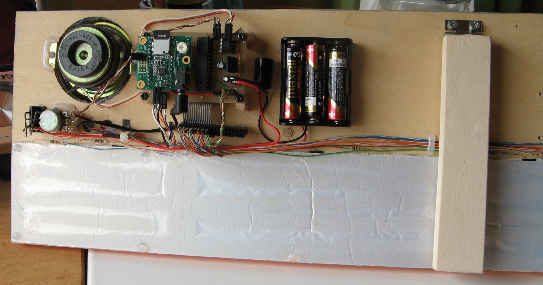
Project complete - video and future steps
10/05/2016 at 10:58 • 0 commentsThe device has been complete for several weeks now, but I've been procrastinating here. Finally, here is a short video demonstrating the device.
And here are some pictures.
![]()
![]()
![]()
Everything works pretty well, but I haven't had a chance to use it in the class because we haven't practiced harmonica for a couple months. Hopefully we'll get back to practicing soon. The other teachers saw it and said "What?! How did you...?" like I'm some kind of wizard. For reference, they are still using cassette tapes and VHS despite owning more modern electronics just because they couldn't be bothered to learn how to hook them up. But that's not what this log is about.
The future -
I want to make better recordings of harmonica notes, because the ones I made sound pretty bad. A simple square wave would be almost as good.
I have been modifying the frequency detection code used by the Teensy noteFreq library to more accurately implement the Yin algorithm and open up the possibility of multi-note detection. Once I get a version I'm satisfied with, I'll contact Collin Duffy, who wrote the library to suggest the update.
As I find bugs and figure out better ways of doing things, I'll post updates here.
-
Remote keyboard
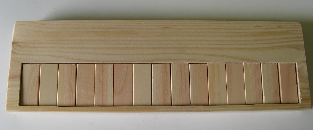
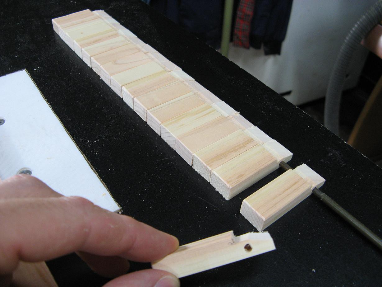
06/19/2016 at 04:24 • 0 commentsThe main unit is pretty much complete aside from a plastic cover for the electronics and legs to hold it up. The second part of the project is the remote keyboard. It is a small, 15-key keyboard that communicates via IR with the main unit. When a key is pressed, the note is lit up and a sound played. Here is my progress so far.
![]()
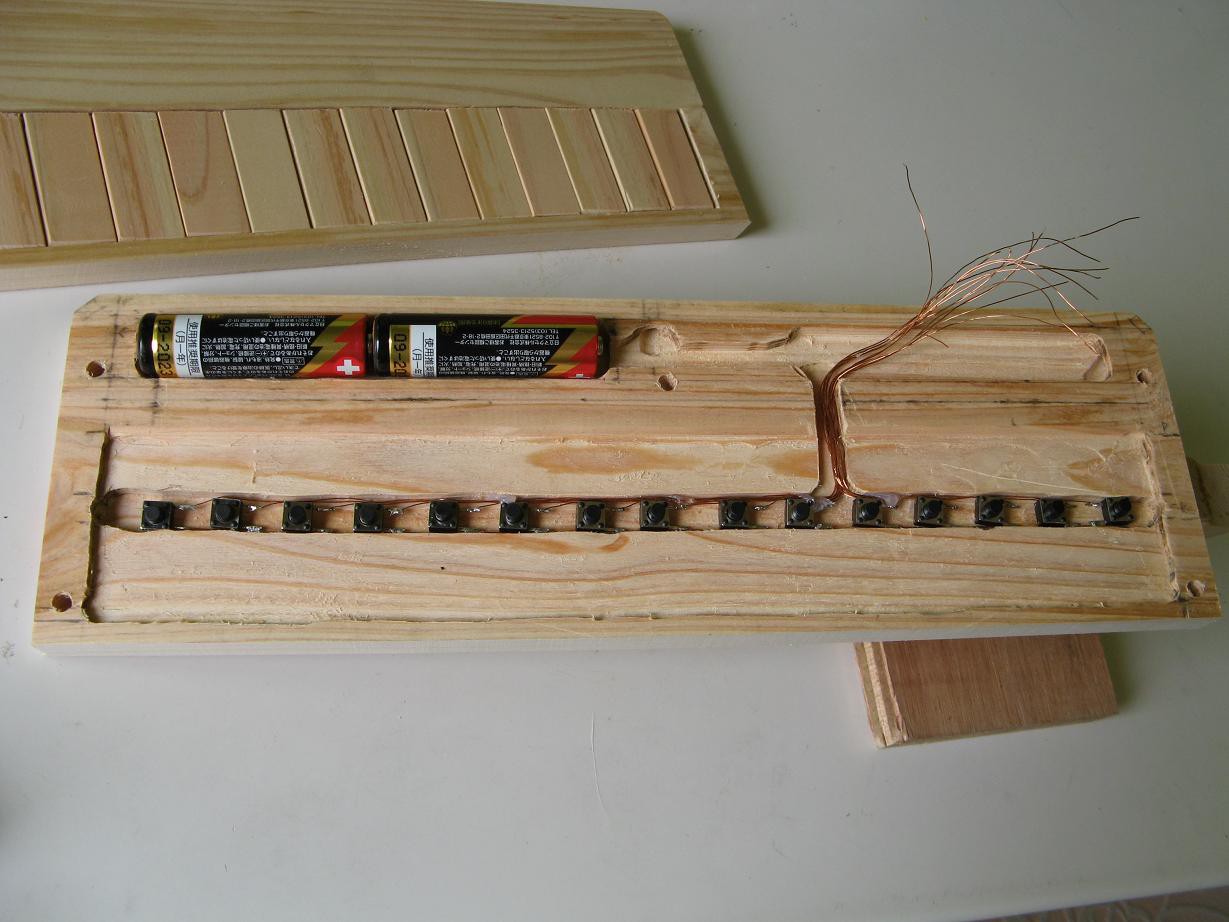
I started with a 1cm thick Japanese cedar board. 15 keys were cut out that will pivot on a stiff steel rod.
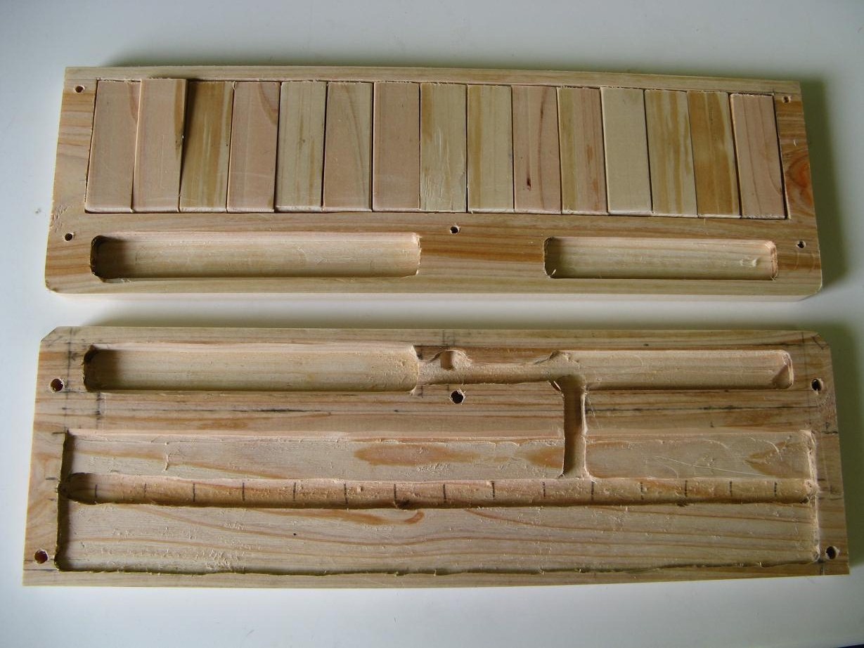
![]()
Then a router was used to cut two pieces like this. The keys are installed here.
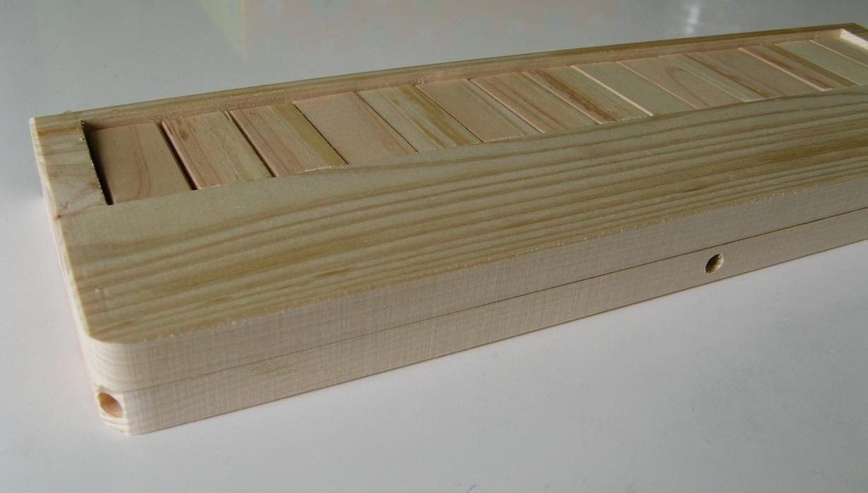
![]()
It looks a little nicer from the outside. The holes are for the LEDs.
![]()
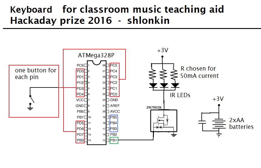
![]()
With the structure built it was time to tackle the electronics. Here is a rough schematic. It is very simple.
![]()
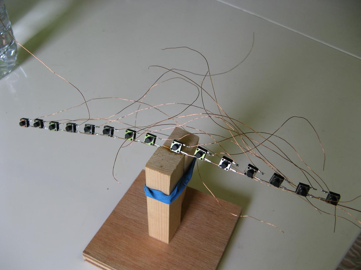
I soldered the tact switches to a solid wire and lots of small magnet wire. It looks like medusa, but it wasn't that hard to do.
![]()
After a little combing and some help from my good friend, hot glue, here it is placed in the case. It's not permanent yet of course. I would have gotten further, but I ran out of solder. Well, I'm off to the store to buy some now.
![]()
-
Code uploaded, all LEDs wired up and ready
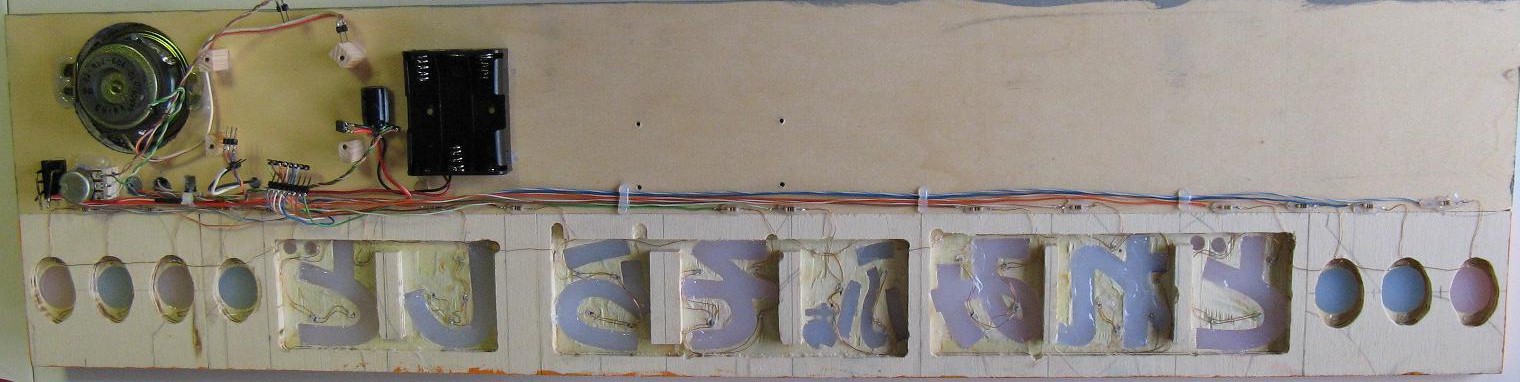
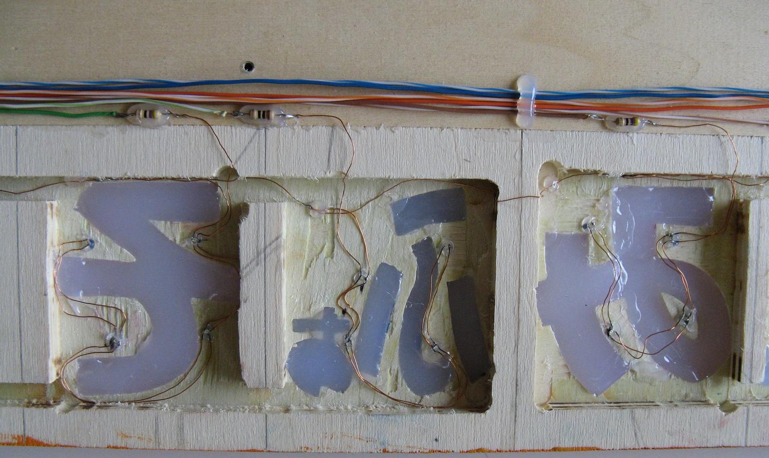
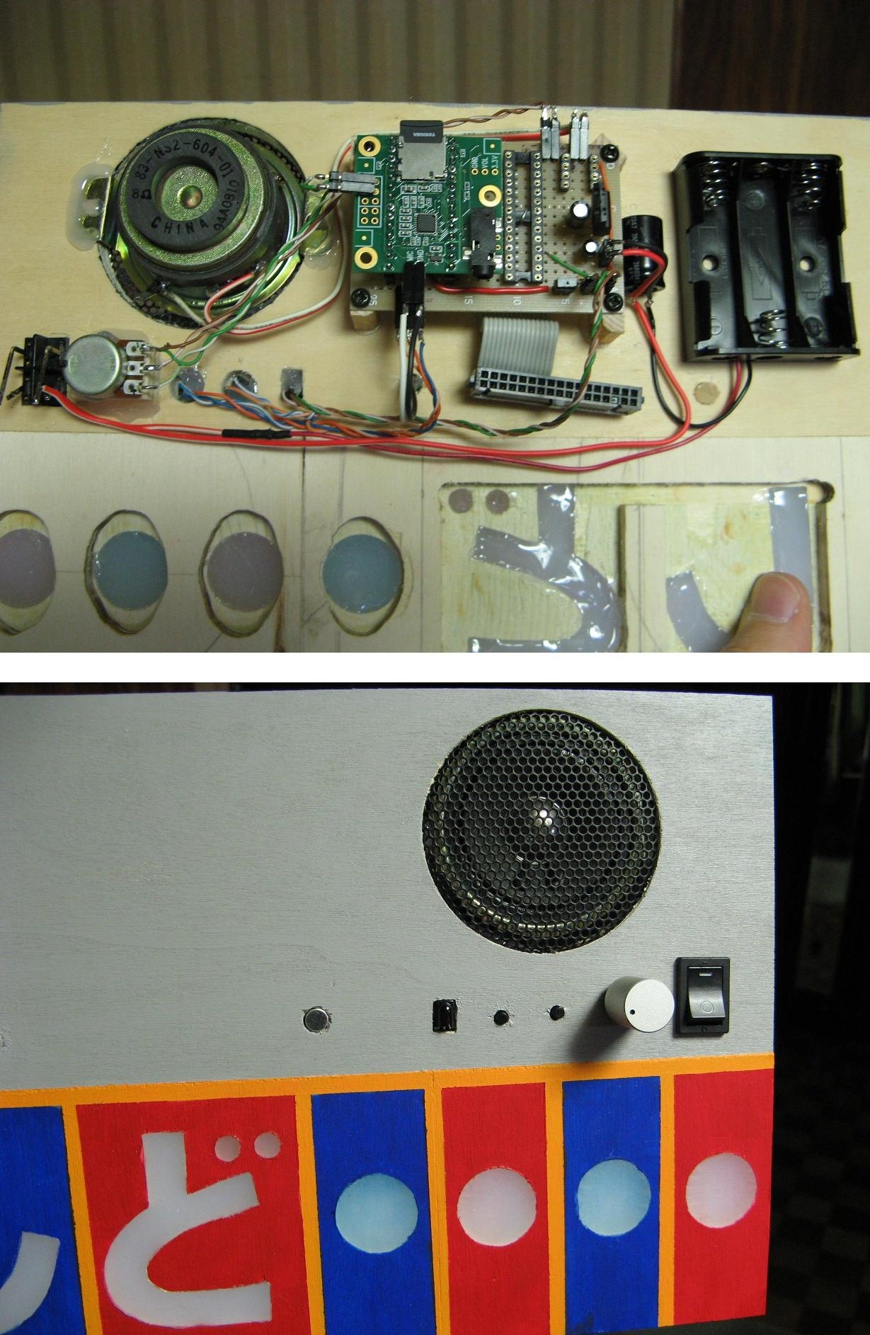
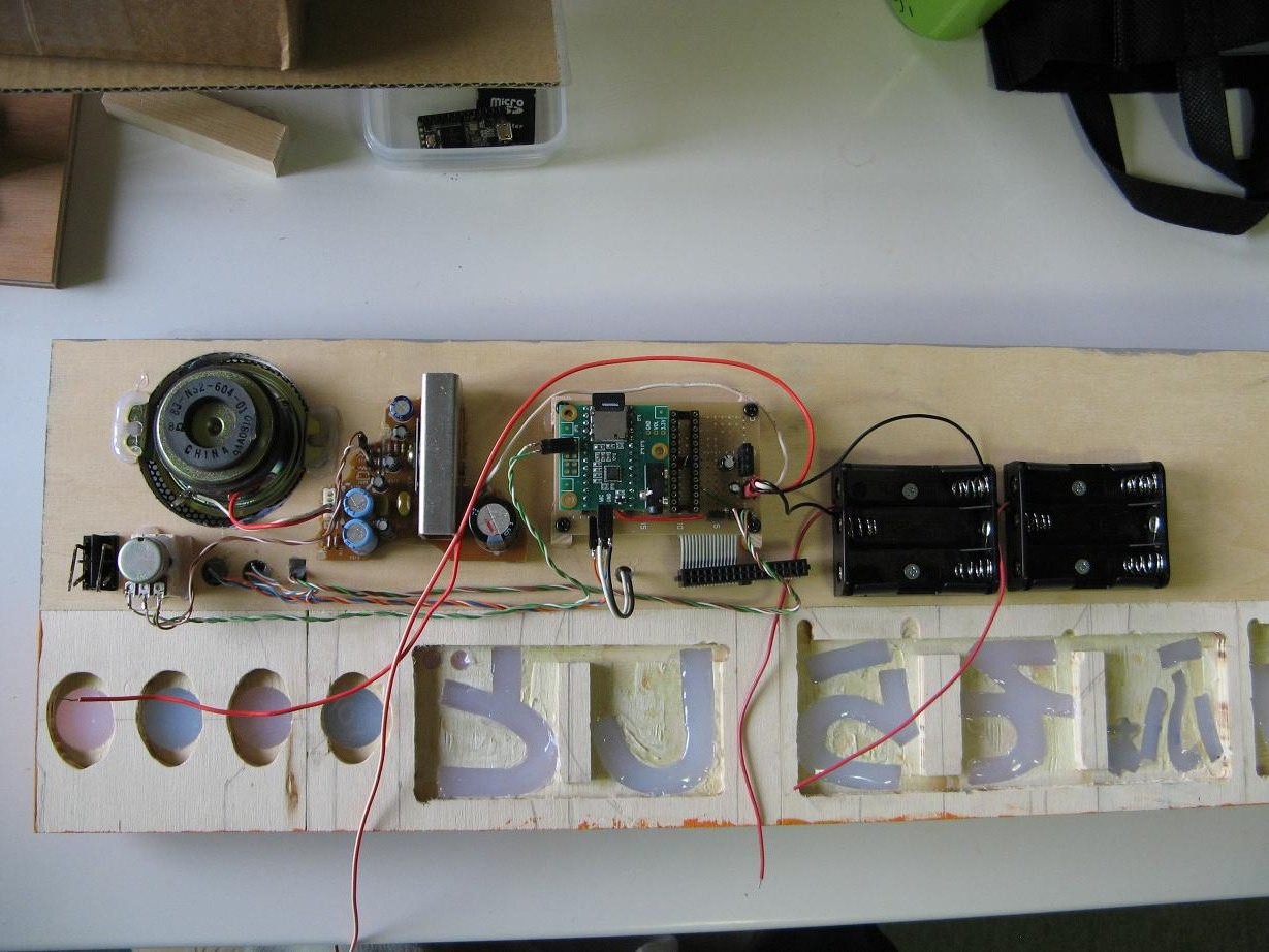
05/29/2016 at 12:28 • 0 commentsAfter many long hours with soldering iron and glue gun in hand I am finally done with the LEDs. The circuitry is complete for the main unit. This is a large milestone. Here are some pictures with the LEDs wired up before I attached the foil coated plastic covers. By the way, I tested them out with the covers on and I can't get over how perfect the illumination looks. Sorry if I keep bragging about that, but it's not so often that my ideas work out that well.
![]()
![]()
Code uploaded
The code for the Teensy and the ATmega LED/IR controller are up on the git.
It will no doubt change as the project develops, but at this point it seems functional.
What's next? - The next steps include
- Testing both hardware and software and refining it as desired.
- Building the remote keyboard, both structurally and electronically.
- Writing code for the keyboard.
- Attaching some legs so that it stands up, and other minor details.
-
Soldering lots of tiny LEDs
05/22/2016 at 06:57 • 0 commentsI hesitantly plugged in my soldering iron today and set to work on the arduous process of wiring up the LEDs. You may think that soldering up 46 LEDs is no big project, but these are wee little 1608 smd LEDs being soldered to thin magnet wire with an uncontrolled 30watt iron. This demands a jig, so I made this simple clamp to hold the LED while I hold wire in one hand and iron in the other.
![]()
Here's one down, 45 to go.
![]()
The circles only need two LEDs and the wires are all the same, so I started with those. Here is one glued in place and lit up.
![]()
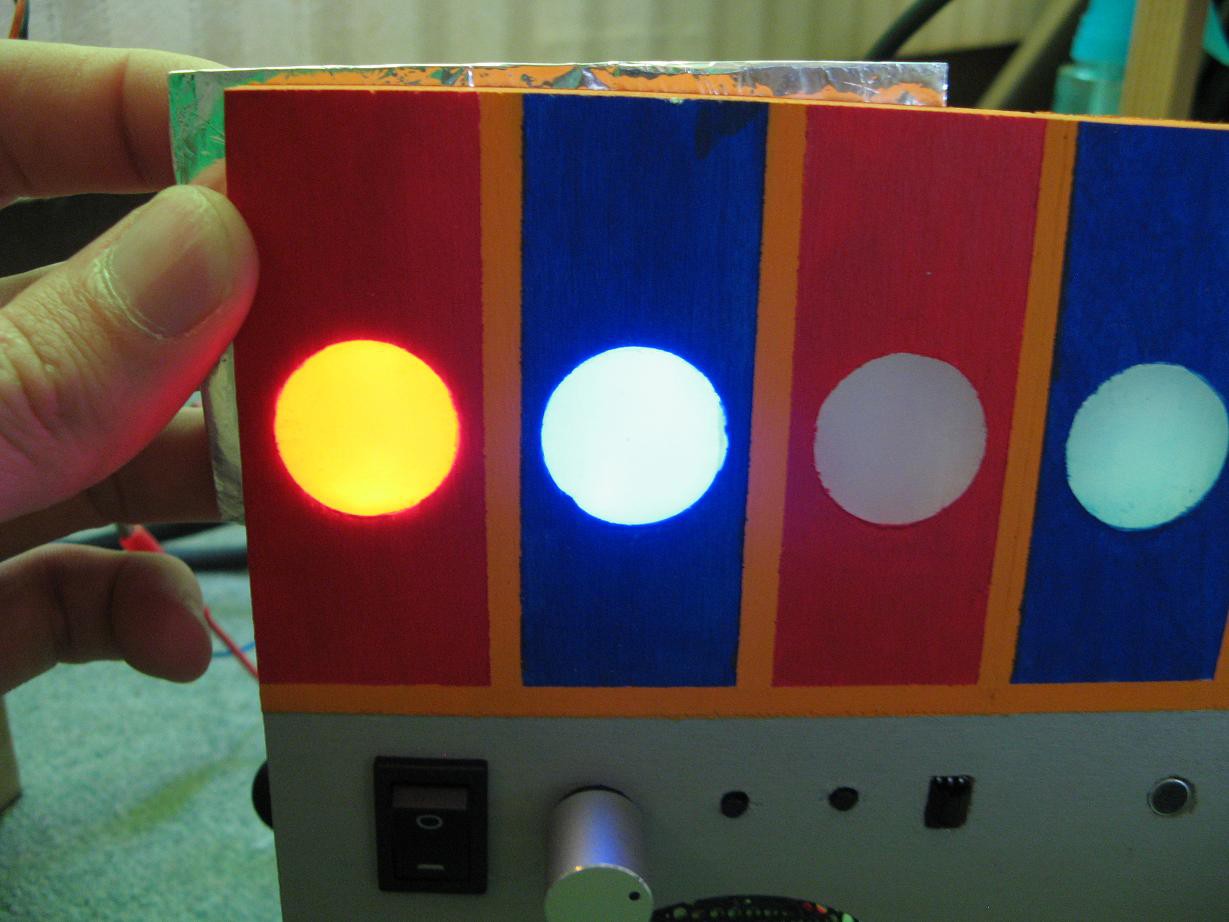
And here are one red and one blue from the front with a foil back plate held in place. For some reason my camera could not capture the true colors. They do not look yellow and white as in the picture. They are the typical red and blue LED colors and they look fantastic. I can't wait to get the rest finished. At this point I have the seven circles and the two ど characters done.
![]()
Software!
It's about time. I got the code for the Teensy and the ATmega(LED and IR controller) written. I've run a few tests and it seems to work alright, but I can't fully test it until I get the whole circuit put together, which means the rest of those LEDs. I don't want to post the code here till then, but it is coming soon.
-
Making it more reproducible(open) and wiring it up
05/16/2016 at 12:40 • 0 commentsI have a tendency to scavenge. When designing and sourcing parts I always dig through my scraps and try to make use of them. I like doing that and I think it's a good thing. Plus it certainly increases the hack factor(hackiness?) of my projects. My decision to use an audio amplifier torn from the carcass of a dead stereo is a good example. But it also makes the project somewhat less reproducible because anyone wanting to copy my design isn't going to have the same junk pile.
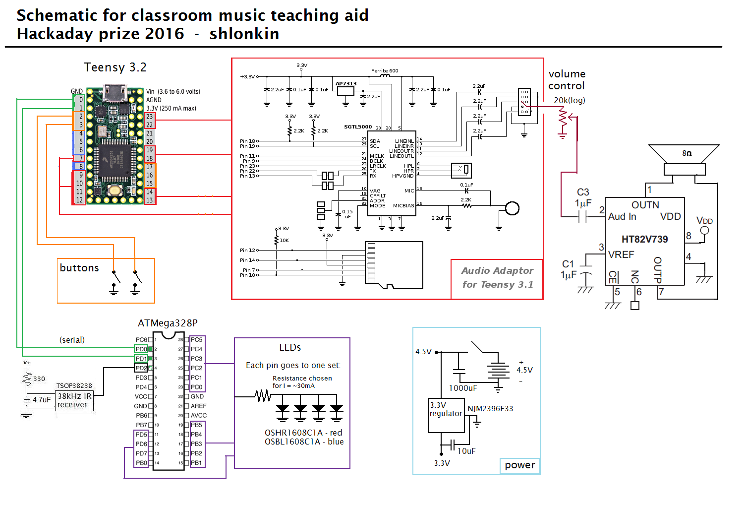
In the interest of making this project more easily reproducible, and thus open, I redesigned the audio output part of the circuit to use easy to source parts. And while I was at it, I designed it to be much more suitable for this application. Here is an updated schematic.
![]() The main difference is the HT82V739 audio power amp on the right which replaces that big chunk of circuitry I had before. One other change is the removal of the second battery pack since this amp is designed for low voltage, battery powered devices.
The main difference is the HT82V739 audio power amp on the right which replaces that big chunk of circuitry I had before. One other change is the removal of the second battery pack since this amp is designed for low voltage, battery powered devices.Although I'm still waiting for the amp to arrive, I soldered the circuit up and assembled the rest of the circuitry, except for the LEDs. Here is the new version of the board sandwiched between the Teensy and audio shield. The amp goes in the small socket on the top right.
![]()
And here it is all assembled. Note that familiar looking connector on the ribbon cable. That will connect to all the LED segments. Since I'm still in the prototype design stage I want to be able to disassemble everything easily, so everything is connected via pins and headers rather than soldering directly.
![]()
Just for comparison, here is what the previous version looked like. It was much larger and more complex. I like the new version much better.
![]()
-
Solder, glue and paint
05/06/2016 at 12:47 • 0 commentsSolder
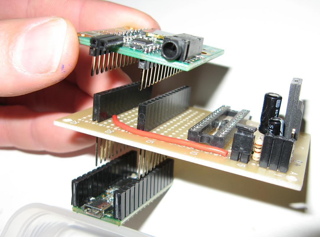
I know you'd rather hear about the solder, so I'll start there. The central part of the electronics is the Teensy3.2, Audio adapter, and LED driver(ATMega328) which all stack together in a small package. First take a look at the picture. The perfboard sandwiched between the Teensy and audio adapter holds the ATMega328, 3.3V regulator for powering everything, various connectors, and eventually will have a whole mess of wires(15) soldered to it for the LEDs. See the schematic for more details.
![]()
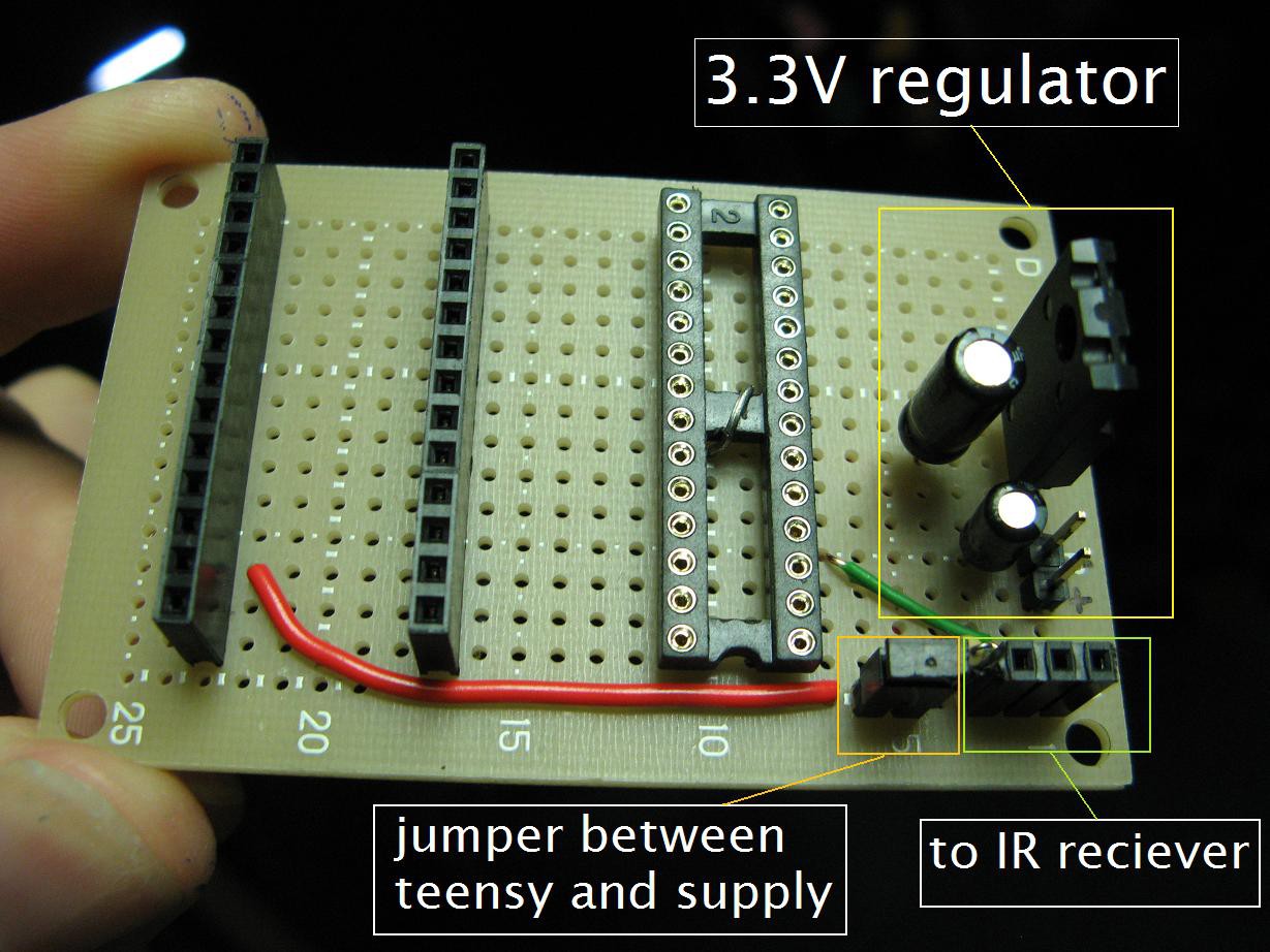
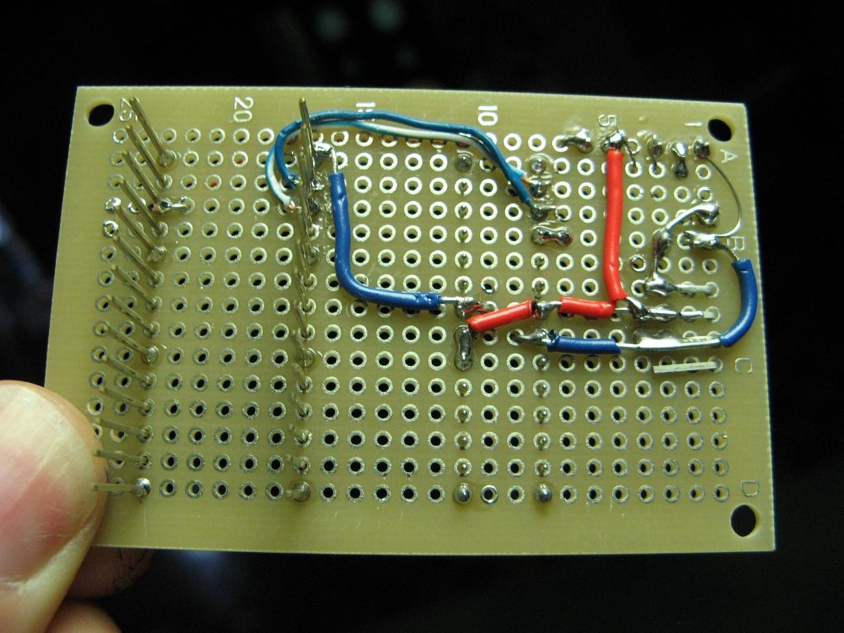
Here are a couple more shots of the middle board.
![]()
![]()
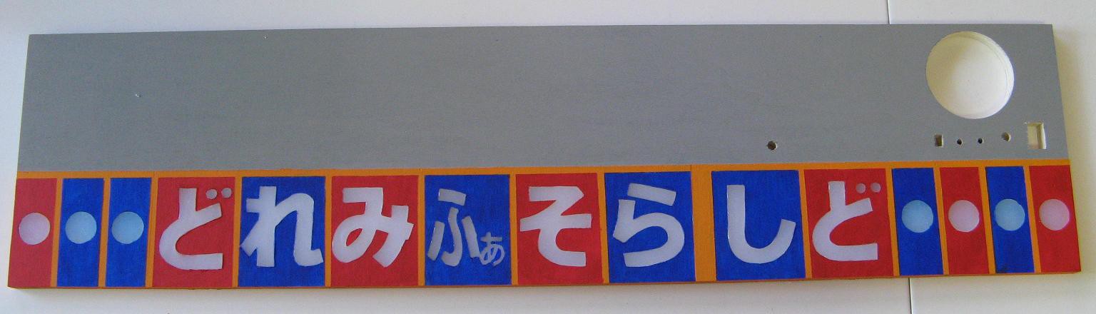
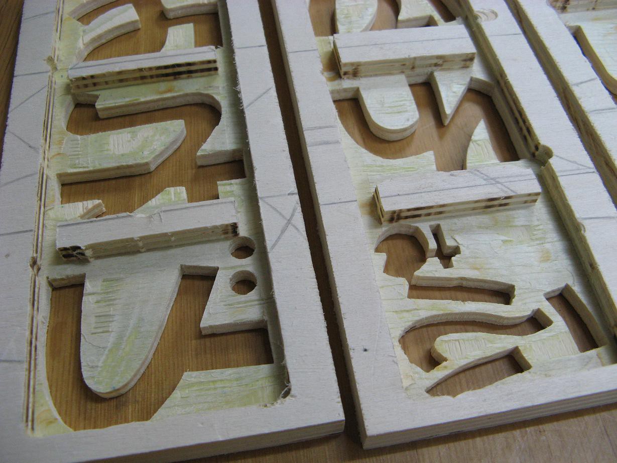
Glue, Paint, Glue
Remember all those wood pieces I made a couple weeks ago? I made another piece for the top portion where all the electronics will be mounted. It has a bunch of holes for speaker, mic, switches, etc. I glued them together, painted them and filled the characters with hot glue from the back while the front is sitting on baking sheet on a flat surface. I think the result looks awesome.
![]()
![]()
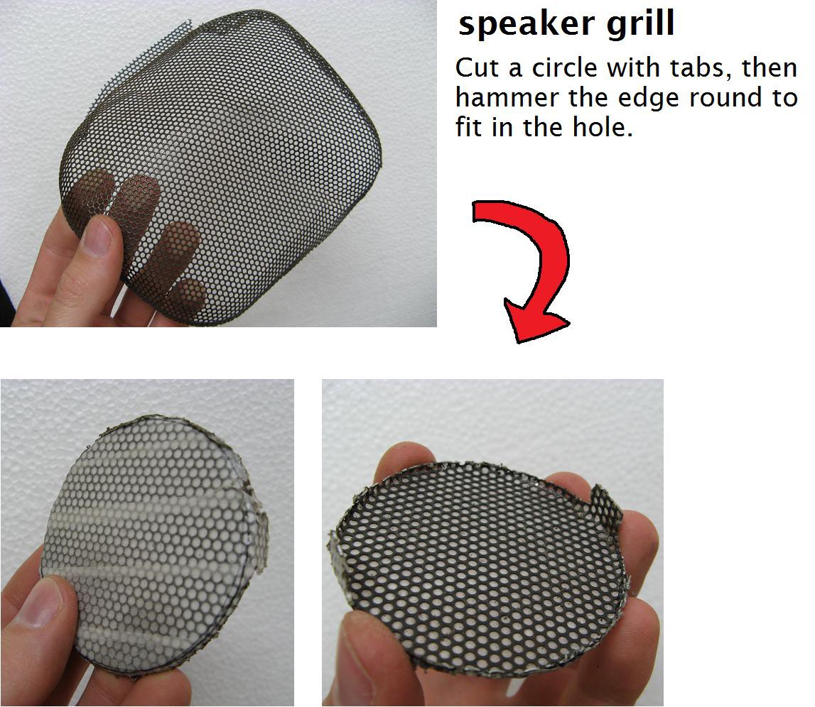
And for one more cosmetic touch, I made a speaker grill. The grill was torn out of a junk stereo, the one that I tore to pieces in a previous log, modified. I pounded it flat, cut a circle slightly larger than the hole, hammered the edge down till it fit just right, and painted it flat black. It came out better than I expected.
![]()
-
Some design improvements
04/26/2016 at 13:01 • 0 commentsI stepped back and looked at this idea from the perspective of a teacher using it in a classroom because, well, I will be using it once it is complete and I don't want to think "Oh, I should have done that differently." I decided to change the design and functionality in the following ways:
- The remote will be a small 15 key keyboard. This is by far the most natural arrangement since myself and the other teachers are used to playing piano. I will likely design and build the keyboard remote myself unless I come across one that is just right.
- It will not play a collection of songs. Although this sounds like a nice feature, it would not be very useful. It is vastly simpler to just play the song on the keyboard remote rather than select the song, set the tempo and try to play back the parts of the song they are currently learning.
- There will be no display. The only real use for the display was selecting songs and setting tempo. Without that functionality, the display just adds needless complexity, cost and power drain.
- The control interface on the main unit will consist of: a power switch, a volume knob, and perhaps two buttons for recording and playback, though I'm still thinking about that function.
Here is an updated schematic
![]() And here's an updated basic diagram
And here's an updated basic diagram![]()
-
A small mountain of sawdust and a thing of beauty
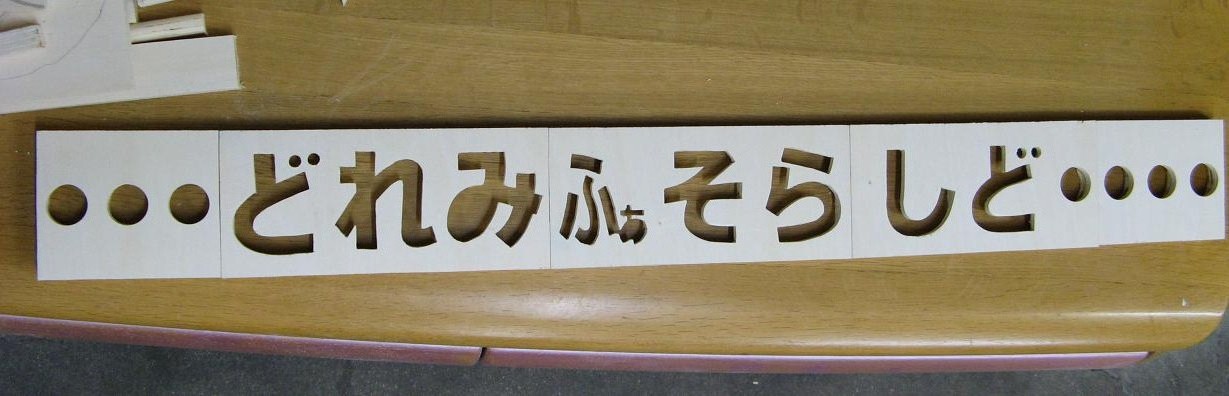
04/18/2016 at 13:34 • 0 commentsOh, the cutting! I walked into the workshop with determination and a plan. I staggered out five or six hours later with a handful of plywood chunks and a satisfied grin. I will show you why.
![]()
Isn't that cool? Lined up it's about 72cm long. Here's another view.
![]()
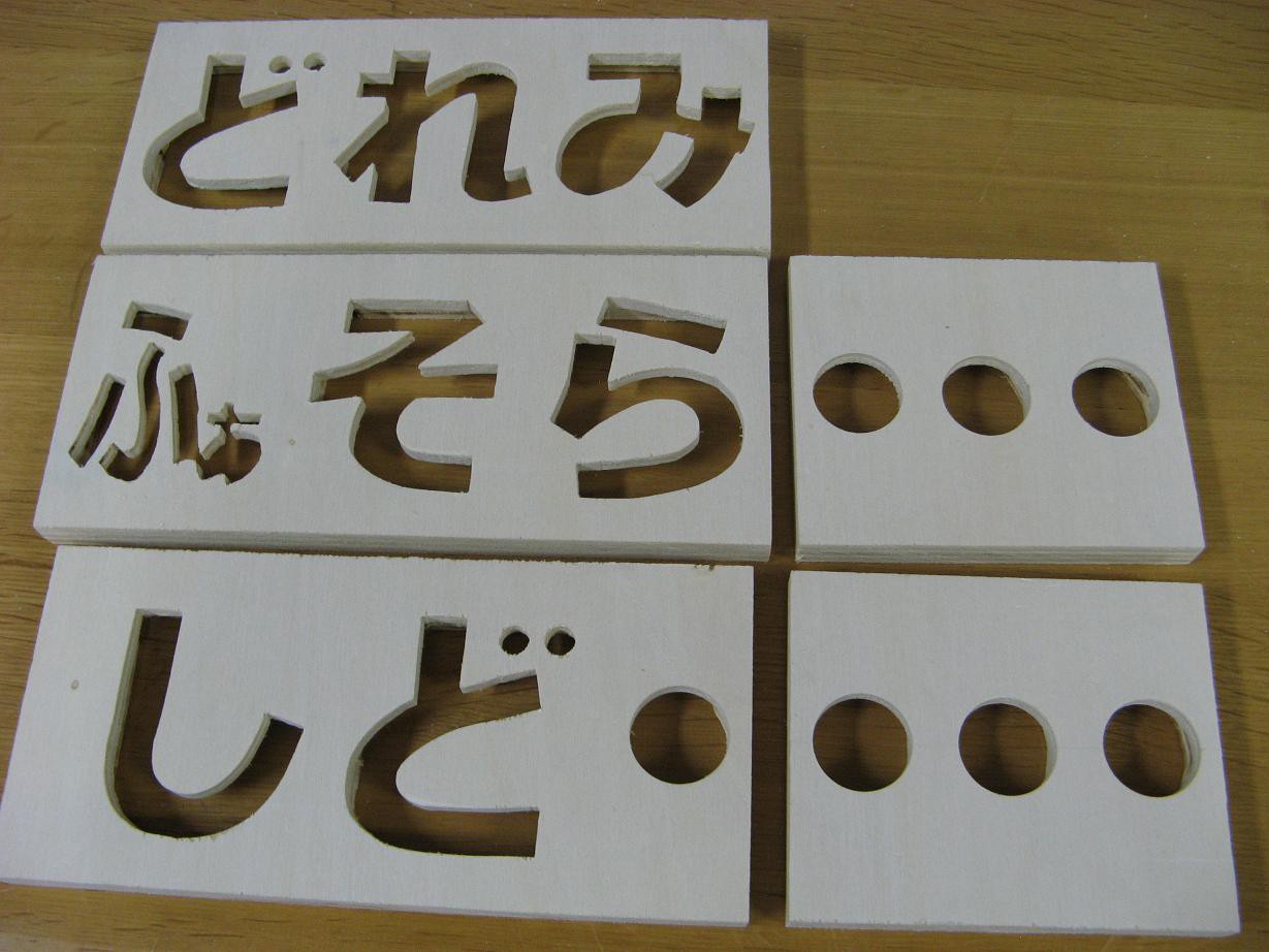
I took some scraps of poplar plywood, carefully massaged them with a scroll saw, and hollowed out the back with a router as you can see below.
![]()
They aren't perfect. I didn't worry about making the back sloppy since it won't be visible. But I'm overjoyed with how well everything came out. It's better than I was expecting for a first try.
Before I start soldering up a huge number of smd LEDs on tiny magnet wire, a job I'm not looking forward to, I'm going to make the top half, glue it together, paint it, and fill the characters with hot glue.
On the more electronic side of the project, I've been testing out the various parts of the circuit and writing software. Man, Paul Stoffregen is my hero. His Teensy, audio adapter and supporting software have done all the hard parts for me. Thank you.
-
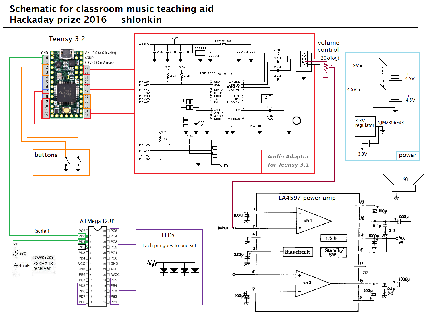
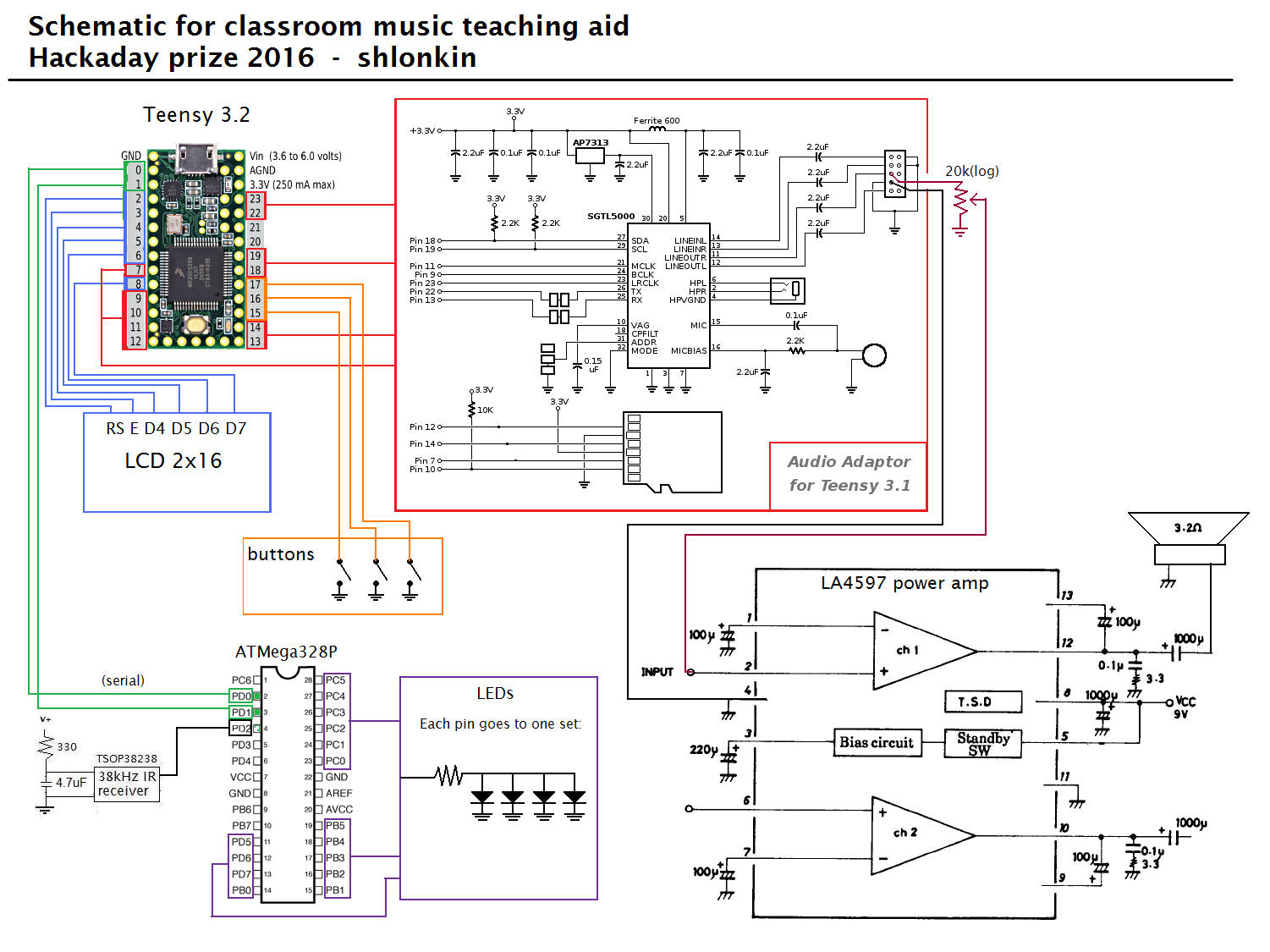
Finally, a complete schematic and working audio output
04/14/2016 at 14:17 • 0 commentsIt's about time I got an actual schematic on here. This is likely to change a little as things develop.
![]()
I've also got the audio output part working now.
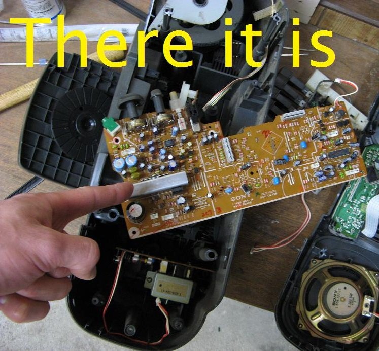
I am pretty new to audio circuits and the little I do know comes mainly from datasheets and schematics. After several frustrating hours trying to design an audio output circuit with the parts I had on hand, I picked up a hammer and chisel and took out my frustration on an old portable stereo from a garbage pile. Amidst the resulting plastic rubble and circuit boards I found just what I was looking for, the power amp circuit.
![]()
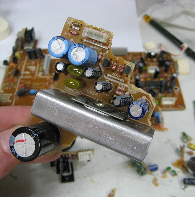
It's a pretty simple circuit that was designed to run on 9V and has reasonable quiescent current of about 20mA(compared to some of my larger amps that were over 100mA). The next task was to remove it from the rest of the board, so after carefully following all the relevant traces, I marked out the section I need. Then I grabbed a utility knife and pliers and recklessly scored and snapped the board, crushing unimportant components and tearing leads from things that got in my way. The result is not pretty, but everything I need is intact.
![]() Just to make sure this would work I rigged everything up and plugged it into the headphone jack on my computer. Everything worked well. This is encouraging.
Just to make sure this would work I rigged everything up and plugged it into the headphone jack on my computer. Everything worked well. This is encouraging.![]()
-
New illumination idea - awesome results
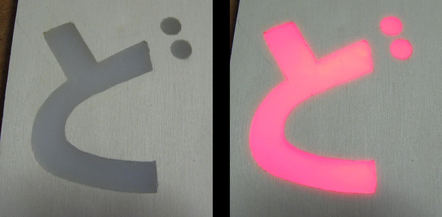
04/03/2016 at 14:17 • 0 commentsI'll start by showing you the result:
![]() Now I'll tell you how I got there. Here is a rough sketch of the idea.
Now I'll tell you how I got there. Here is a rough sketch of the idea.![]()
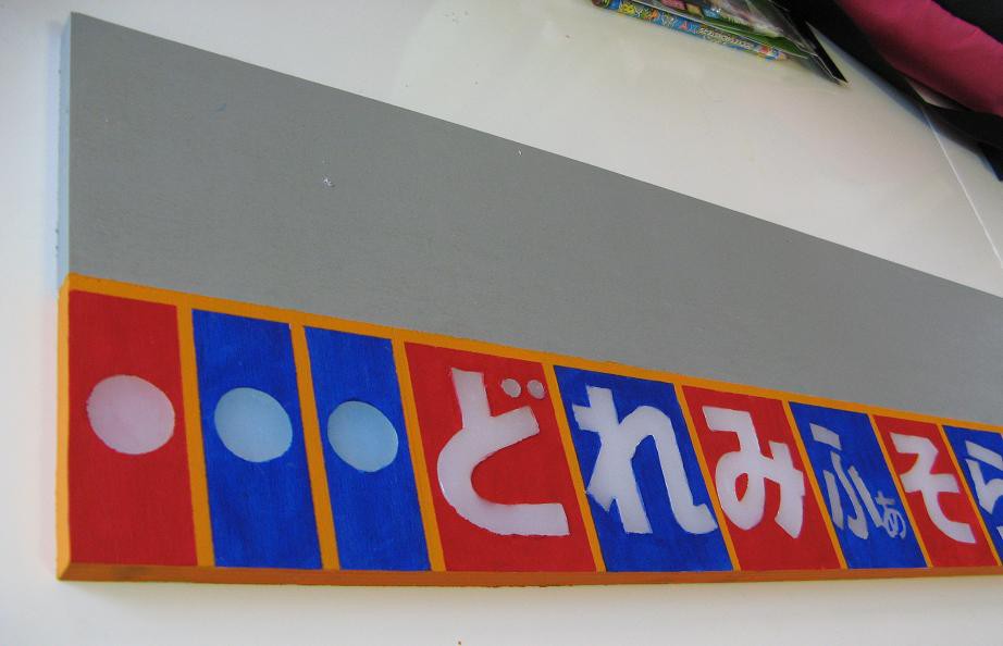
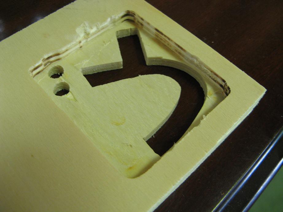
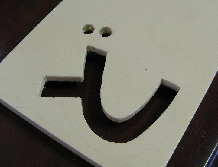
I started with a little scrap of plywood. This was just a proof of concept and won't actually be used, so I wasn't overly concerned with details, but it came out much better than I expected. First I cut out the design with a scroll saw(homemade saw, but that's another project). Then used a router to make a void in the back. By the way, that's the Japanese character for "do" as in the musical notes: do, re, mi, fa, so, la, ti.
![]()
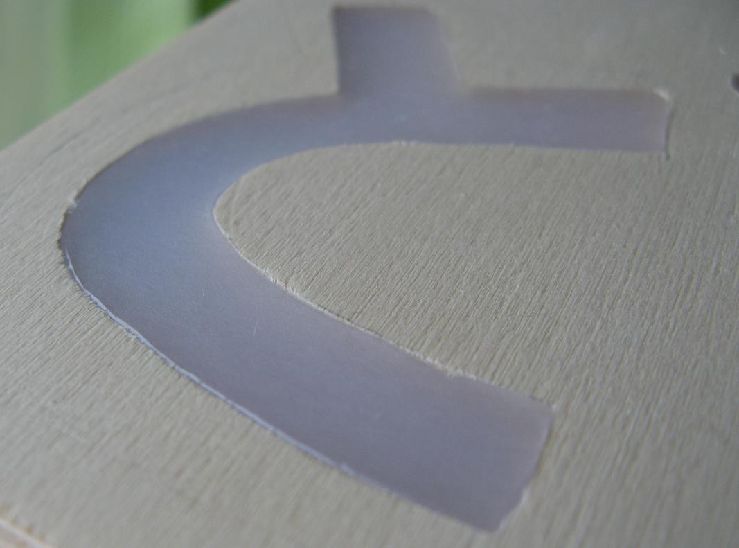
![]() I'm using nice poplar plywood that is sooo nice to cut. Anyway, then I set it face down on some silicone baking sheet and carefully, to avoid bubbles and empty corners, filled it up with hot glue.
I'm using nice poplar plywood that is sooo nice to cut. Anyway, then I set it face down on some silicone baking sheet and carefully, to avoid bubbles and empty corners, filled it up with hot glue.![]() After giving it plenty of time to cool, it lifted right off the sheet and looked like this.
After giving it plenty of time to cool, it lifted right off the sheet and looked like this.![]()
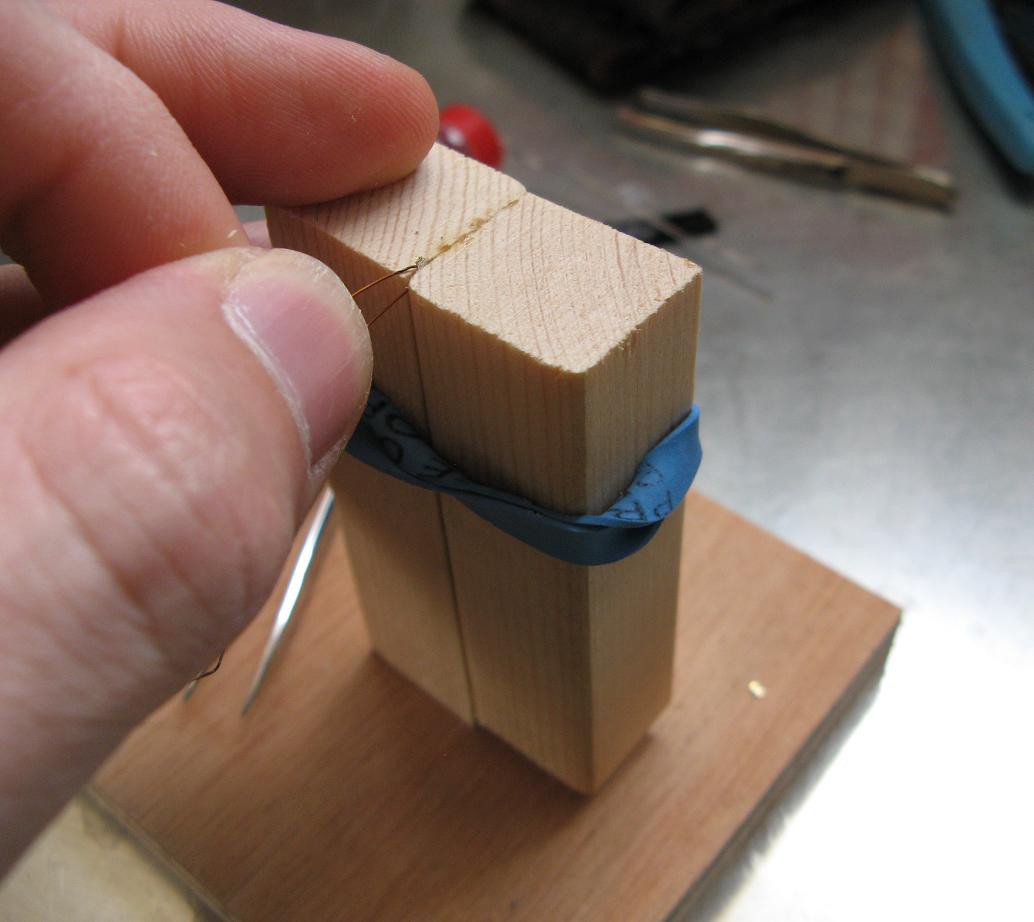
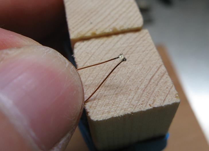
![]() Then it was time for the hard part. With tweezers and a way overpowered soldering iron I managed to attach four smd LEDs to some magnet wire. I somehow managed to get them all successfully connected in the right orientation on the first try. Then I tacked them on the wood with hot glue.
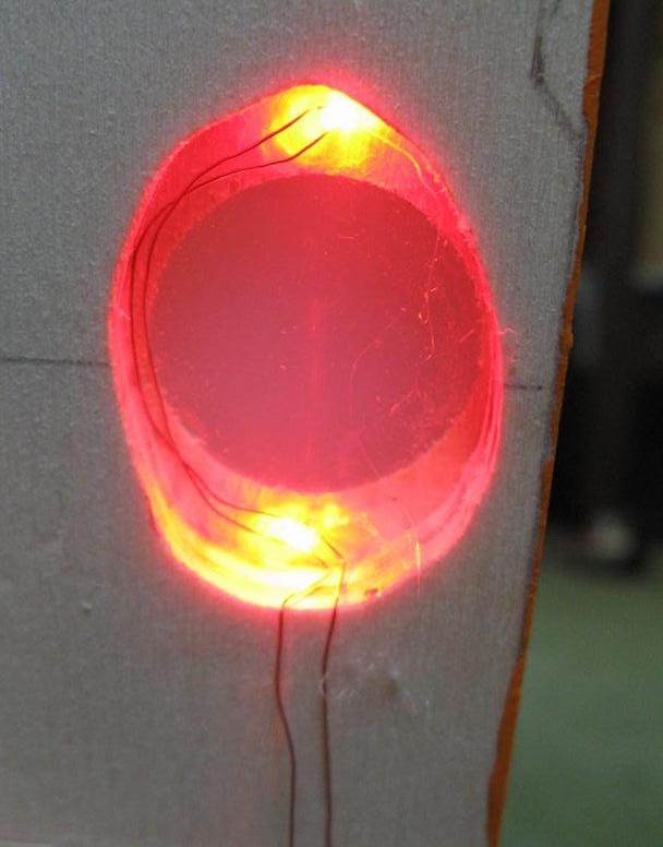
Then it was time for the hard part. With tweezers and a way overpowered soldering iron I managed to attach four smd LEDs to some magnet wire. I somehow managed to get them all successfully connected in the right orientation on the first try. Then I tacked them on the wood with hot glue.![]() Here they are with about 50mA going through the set in parallel.
Here they are with about 50mA going through the set in parallel. ![]() I taped some foil onto a piece of milk carton and set the device on top. The result was fantastic. I'll be using this method for the final product. But I'm not looking forward to cutting out some of the more complicated characters. I need: ど れ み ふぁ そ ら し . I think ふぁ will be a nightmare, so I might just cut the ふ part and paint the other.
I taped some foil onto a piece of milk carton and set the device on top. The result was fantastic. I'll be using this method for the final product. But I'm not looking forward to cutting out some of the more complicated characters. I need: ど れ み ふぁ そ ら し . I think ふぁ will be a nightmare, so I might just cut the ふ part and paint the other.![]()
Classroom music teaching aid
An interactive device for helping a kindergarten class learn to play harmonica.

 The main difference is the HT82V739 audio power amp on the right which replaces that big chunk of circuitry I had before. One other change is the removal of the second battery pack since this amp is designed for low voltage, battery powered devices.
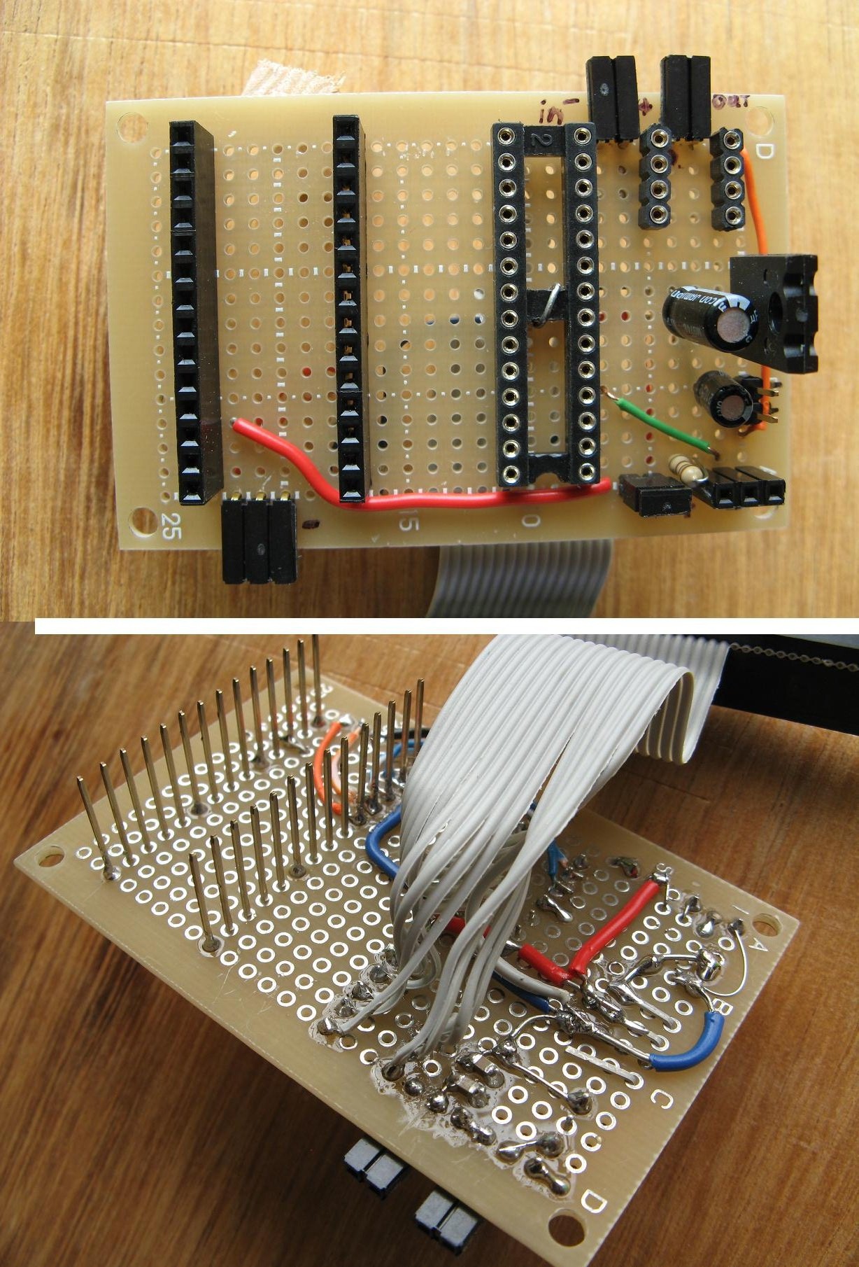
 And here's an updated basic diagram
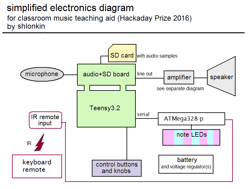
 Just to make sure this would work I rigged everything up and plugged it into the headphone jack on my computer. Everything worked well. This is encouraging.
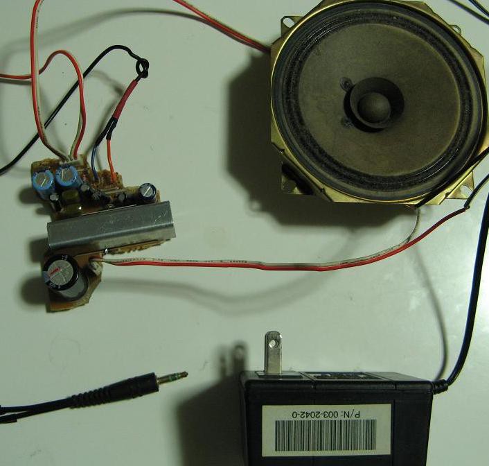
 Now I'll tell you how I got there. Here is a rough sketch of the idea.
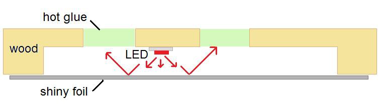
 I'm using nice poplar plywood that is sooo nice to cut. Anyway, then I set it face down on some silicone baking sheet and carefully, to avoid bubbles and empty corners, filled it up with hot glue.
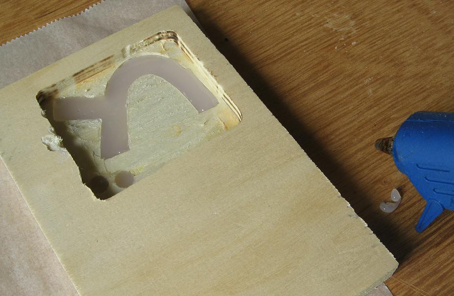 After giving it plenty of time to cool, it lifted right off the sheet and looked like this.
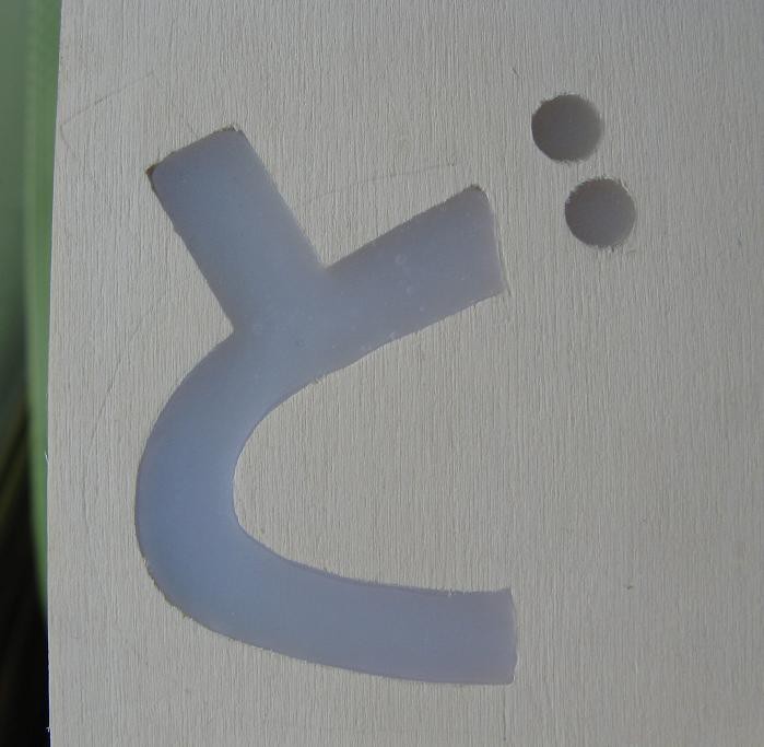
 Then it was time for the hard part. With tweezers and a way overpowered soldering iron I managed to attach four smd LEDs to some magnet wire. I somehow managed to get them all successfully connected in the right orientation on the first try. Then I tacked them on the wood with hot glue.
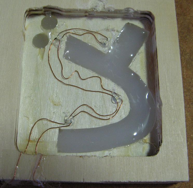 Here they are with about 50mA going through the set in parallel.
 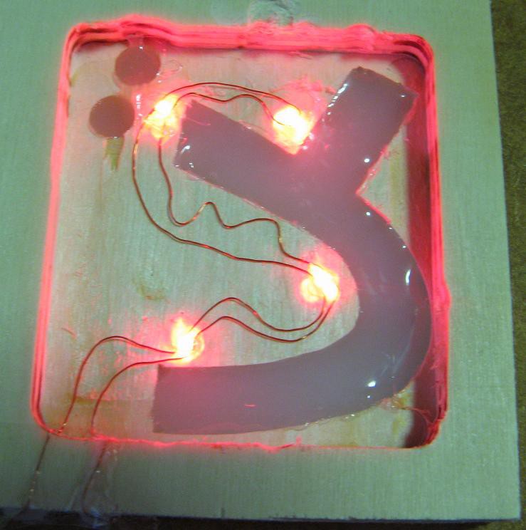 I taped some foil onto a piece of milk carton and set the device on top. The result was fantastic. I'll be using this method for the final product. But I'm not looking forward to cutting out some of the more complicated characters. I need: ど れ み ふぁ そ ら し . I think ふぁ will be a nightmare, so I might just cut the ふ part and paint the other.