Time for another project update...
Breadboard prototype
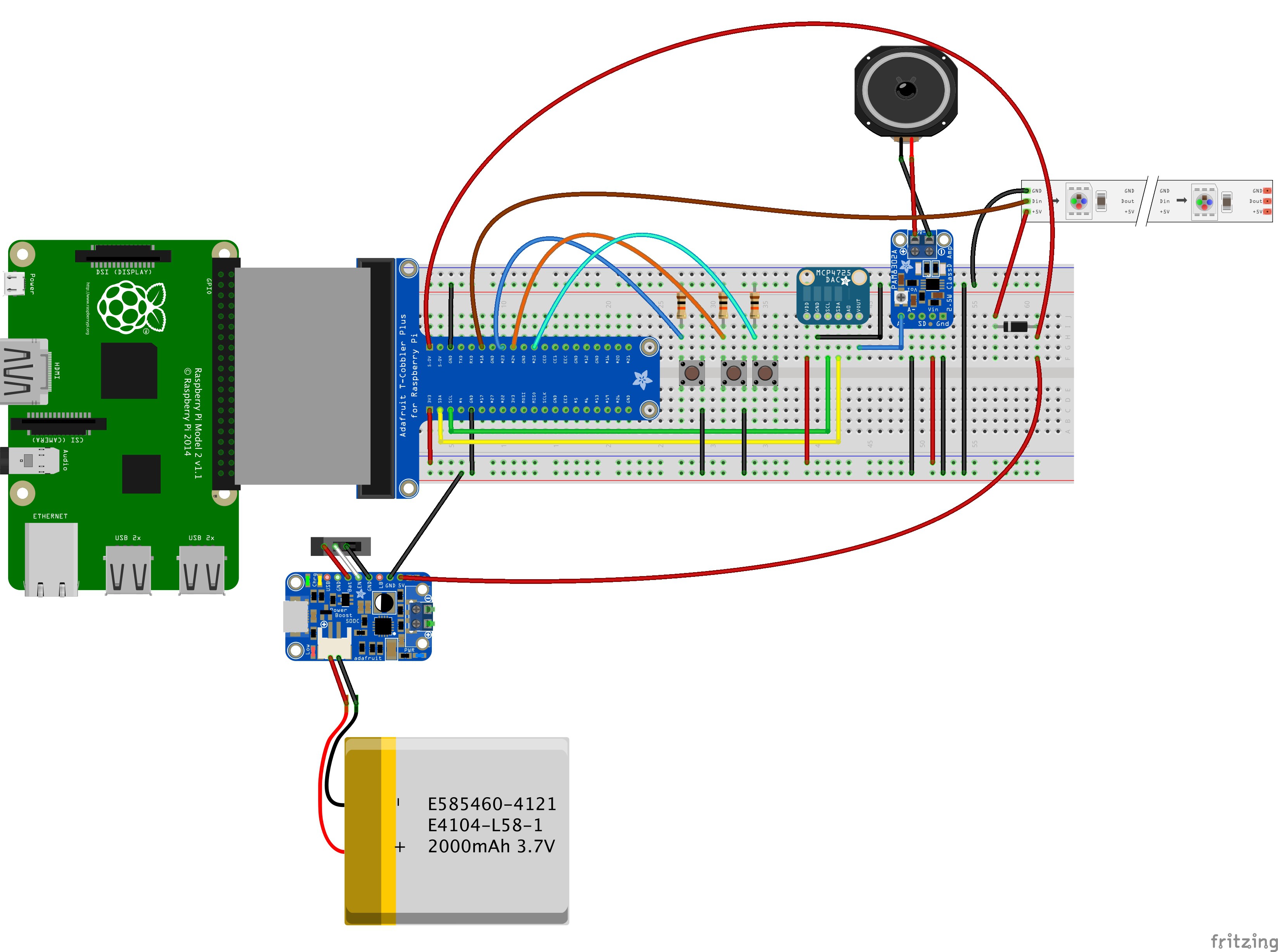
I did not do much coding over the Easter weekend, but instead took some time to get more familiar with Fritzing and think about how to wire up the different components. A few things are still missing, but here is the wiring for the breadboard prototype that I came up with so far:

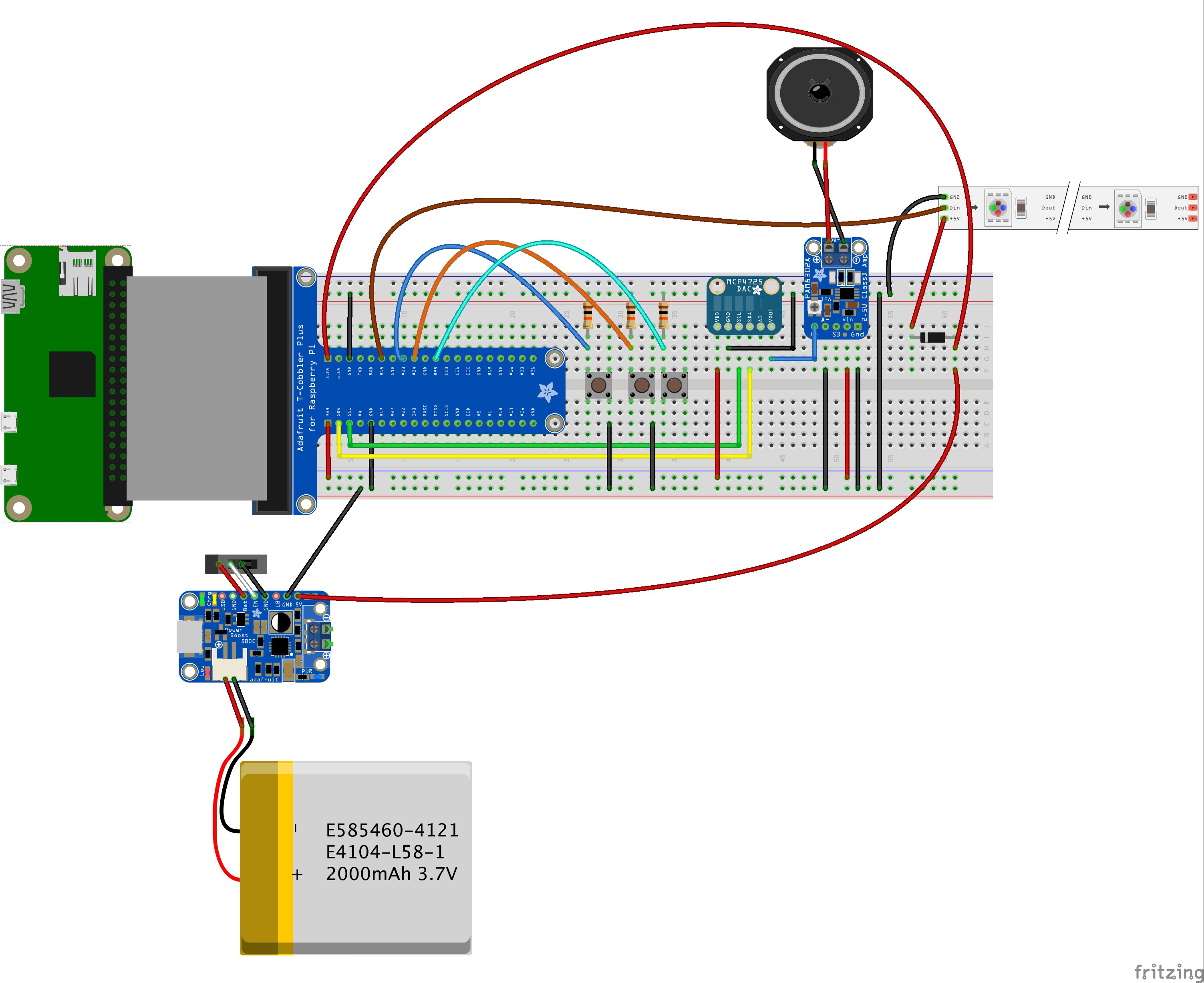
For the Raspberry Pi Zero, the prototype setup looks the same, just with the Pi Zero instead of the Model B(+)/2:

The only thing still missing from the Fritzing sketches is essentially the USB webcam. I'm thinking about creating a custom part for Fritzing in order to complete the sketch in this direction.
The NeoPixel strip in the upper right corner is just for additional lighting when taking a picture. It can be omitted or replaced by a bright white LED or even an external light source.
The T-Cobbler is just used for a cleaner and easier connection between the GPIO pins on the Raspberry Pi and the rest of the parts. It can be considered to be part or the overall wiring.
At the moment, the rest of the parts are as follows:
- 1 Raspberry Pi (model Zero, A+, B+, 2 or 3)
- 1 Adafruit PowerBoost 1000C charger board (the sketch shows a PowerBoost 500C as the library did not contain the 1000C model, but the basic connections are the same)
- 1 rechargeable LiPo battery (a 2000mAh version in the sketch, but other compatible batteries can be used)
- 1 slide switch for the PowerBoost on/off function (this may be replaced later by a different solution that allows the Pi to be shutdown properly)
- 3 momentary pushbuttons - one for triggering the picture taking/scanning process, two for adjusting the audio volume level
- 3 resistors (10 kOhm each) - not sure if these are needed here, but I keep them in to be on the safe side
- 1 Adafruit MCP4725 Breakout Board - 12-Bit DAC w/I2C Interface (used as a replacement for the Pimoroni DAC board)
- 1 Adafruit Mono 2.5W Class D Audio Amplifier - PAM8302 board (necessary to boost the audio signal to a usable level for the speaker)
- 1 flat audio speaker
- 1 NeoPixel stick (Adafruit NeoPixel Stick - 8 x 5050 RGB LED with Integrated Drivers)
- 1 1N4001 rectifier diode (needed for the NeoPixel stick or strip)
This setup should provide enough power for a mobile usage of the Raspberry Pi while also providing audio output for the Pi Zero.
Wiring up the parts
Here are the details for the part connections of the different parts mentioned above:
Raspberry Pi GPIO:
- 5V: connected to the PowerBoost 1000C 5V pin
- GND(1): ground is connected to the PowerBoost 1000C GND pin
- SDA: connected to SDA pin of the MCP4725 board
- SCL: connected to SCL pin of the MCP4725 board
- 3V: connected to VDD pin of the MCP4725 board
- GND(2): connected to GND of the MCP4725 board
- GPIO pin 18: connected to Din pin of the NeoPixel stick/strip
- GND(3): connected to GND pin of the NeoPixel stick/strip
- GPIO pin 23: connected to pushbutton 1 and resistor
- GPIO pin 24: connected to pushbutton 2 and resistor
- GPIO pin 25: connected to pushbutton 3 and resistor
MCP4725 12-bit DAC board:
- VDD: connected to Raspberry Pi 3V pin
- GND: connected to Raspberry Pi GND
- SCL: connected to Raspberry Pi SCL pin
- SDA: connected to Raspberry Pi SDA pin
- VOUT: connected to PAM8302 mono amplifier board A+ pin
PAM8302A 2.5W mono amplifier board:
- A+: connected to MCP4725 DAC board VOUT pin
- A-: connected to Raspberry Pi GND
- VIN: connected to Raspberry Pi 3V pin
- GND: connected to Raspberry Pi GND
NeoPixel Stick/Strip:
- GND: connected to Raspberry Pi GND
- DIN: connected to Raspberry Pi GPIO pin 18
- +5V: connected to 1N4001 diode output side
1N4001 Diode:
- output: connected to NeoPixel +5V pin
- input: connected to Raspberry Pi 5V pin (alternatively to Powerboost 1000C 5V pin)
Powerboost 1000C charger board:
- JST: connected to JST-connector of rechargeable battery
- GND: connected to Raspberry Pi GND
- 5V: connected to Raspberry Pi 5V and 1N4001 diode input
- BAT: connected to left pin of slide switch (optional)
- EN: connected to middle pin of slide switch (optional)
- GND (2): connected to right pin of slide switch (optional)
Optional/Temporary slide switch:
- left pin: connected to PowerBoost 1000C BAT pin
- middle pin: connected to PowerBoost 1000C EN pin
- right pin: connected to PowerBoost 1000C GND pin 2
The next thing to do - apart from finishing the software - will be to solder some additional pins and connections so that everything can be tested. The audio output via the DAC board and amplifier board will also need some additional configuration and testing.
That's all for now.
 Markus Dieterle
Discussions
Become a Hackaday.io Member
Create an account to leave a comment. Already have an account? Log In.