Close
0%
0%

BIG_CLOCK

A basic clock using large 7 segments LCD panels

Similar projects worth following
It is time to do something with these big LCD characters !

You will not find something outstanding here, it's just a clock. I had these 3 inches LCD 7-segments character around and a need of a visible clock.

The LCD panels are Lumex LCD-S101D30TR. They are connected on static way, not multiplexed, 7 segments plus a dot (square).

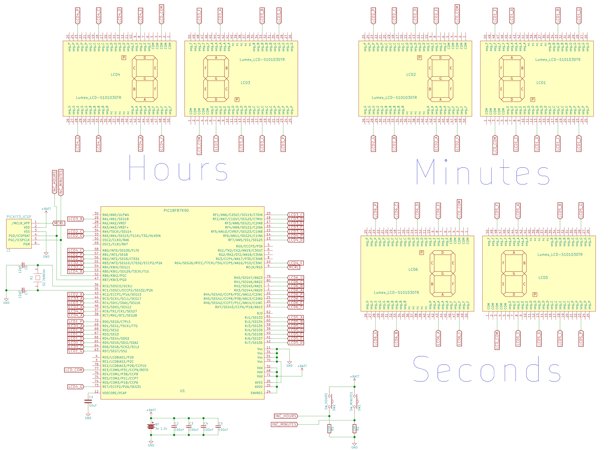
I'm familiar with 8-bit PIC micro controller, and I figured out there is micros with integrated LCD driver. Plus, some have RTC clock modules. I need to drive 6x 8 segments, the PIC18F87K90 - even if it is by far memory over-sized - seems perfect. I could event drive the 6 characters on a static way.

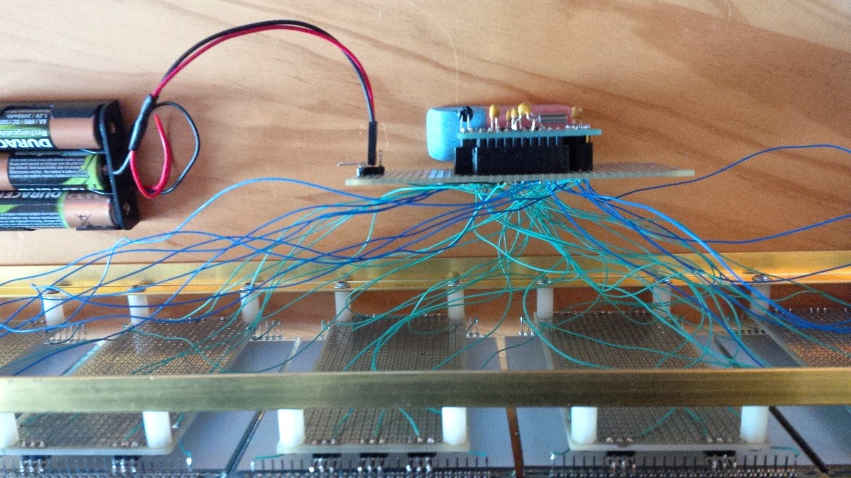
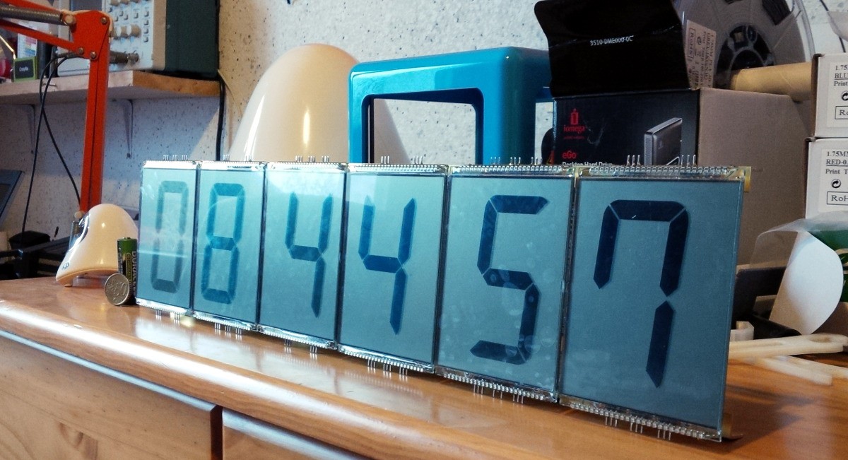
I soldered the LCD panels to prototyping board, which are fixe to long rods.

Everything working on batteries, around 4-5 months on 3 rechargable AA.

main_animated.c

With animations

C Source File - 9.00 kB - 05/21/2017 at 13:10

Download

biglcd_sch.pdf

schematics

Adobe Portable Document Format - 174.54 kB - 05/21/2017 at 13:09

Preview

main.c

First low power version

C Source File - 6.16 kB - 02/20/2016 at 16:35

Download

  • 6 × Lumex LCD-S101D30TR 2.99 inches LCD 7 seg display
  • 1 × Microchip PIC 18F87K90 microcontoller with built-in RTC and LCD driver
  • 1 × 32.768 Khz Quartz resonator
  • 2 × 12pF ceramic capacitor for quartz resonator
  • 4 × 100nF ceramic decoupling capacitor PIC filtering power supply

View all 8 components

  • Conclusion

    Muth05/21/2017 at 13:50 0 comments

    I forgot to update few things, such as the schematics with the two buttons to adjust the time and the transition effect.

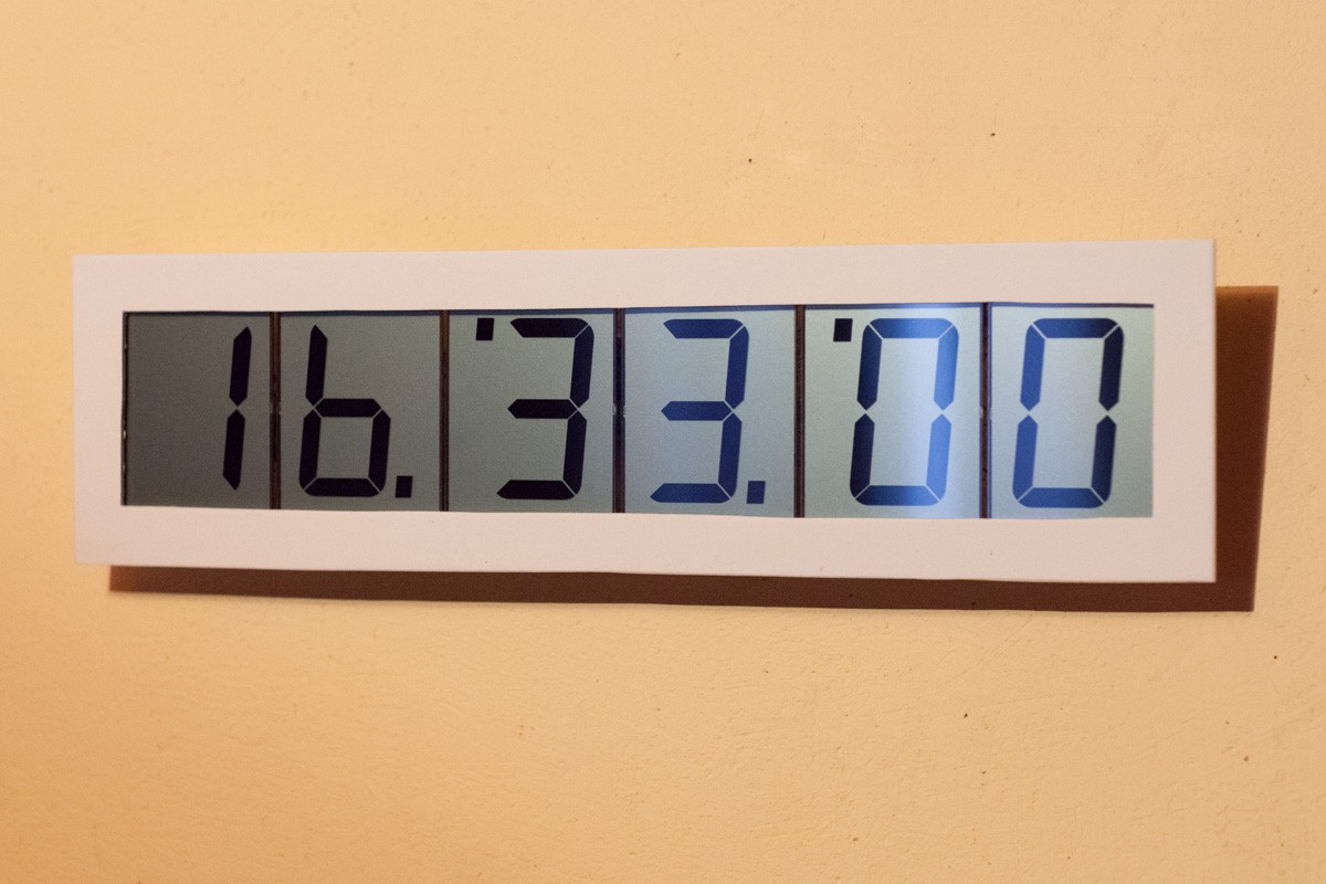
    I changed slightly the code for a more entertaining (supposing a clock could entertain...) transitions each minutes. It's a king of erasing/re-writing effect :

    And you can find bellow and in the project files the schematics with the buttons to increments minutes and hours. I would be silly to have a clock that cannot be set...

    After more than a year of running, I had to recharge the 3 AA NiMH batteries only 3 times. Not bad.

  • Optimisation

    Muth02/20/2016 at 16:15 0 comments

    I spend some time to lower the overall power consumption in order the clock could run on batteries. I'm sure there is still rooms for improvements. The CPU is on sleep, and only the second 32.768Khz oscillator is running for RTC and LCD driving. All unused peripherals are off. It wakes up every seconds to update. Right now everything consume roughly 200uA.

    I used directly 3 NiMH AA batteries, no regulator. That's give voltage between 4V amd 3.3V. Let see if it last at least few month.

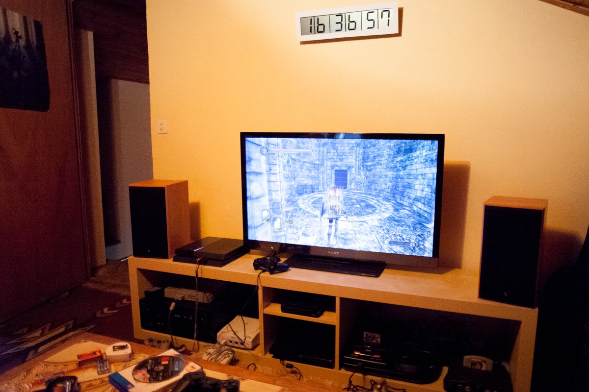
    I made a quick frame :

    And now, no relief ! Could no say "Oh god, I didn't see the time passing while I'm playing...."

  • It is time

    Muth02/16/2016 at 09:59 0 comments

    It is quite tedious to wire and solder 48 segments ! I don't have proper connectors, then I soldered the wires directly between the proto boards. I started to make them following a nice path... But it's ended with a - hum - a nice mess of wires :D

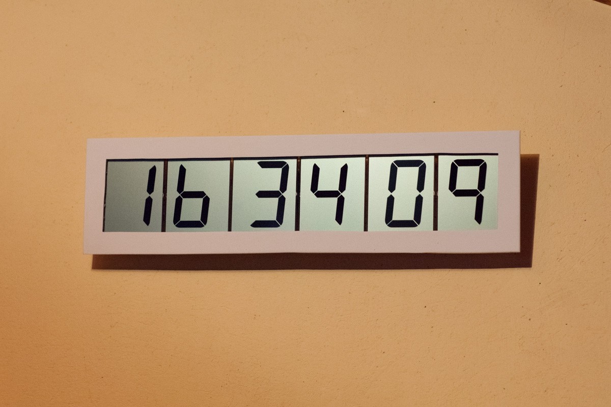
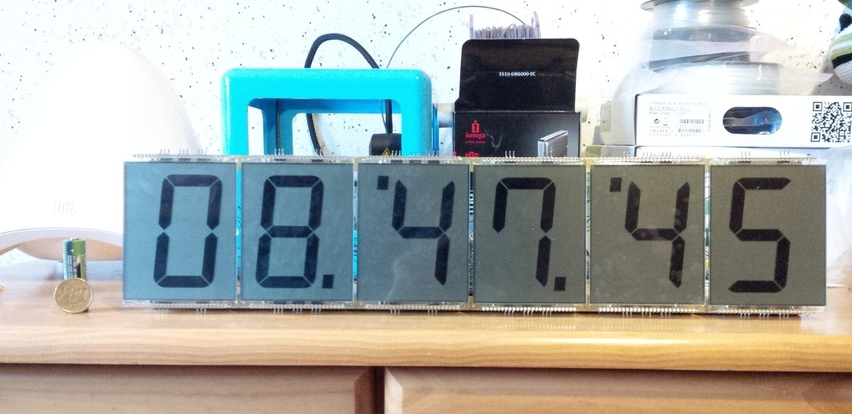
    Anyway, it's working great ! I put the digit alternatively upside down in order to groupe the hour-minute-second numbers. I though in this way it makes the double-dot between each numbers, but it's not exactly what we are use to see. I have to think a bit more about that.

    For the moment it just displays the time with the dots flipping each .5 second. I now have to think about nice digit transitions/animation. As well as study deeply the PIC datasheet in order to put as much as possible parts of the micro in sleep mode to reduce consumption.

    I should not forget to make a frame in order to pass successfully the girlfriend acceptance test...

  • ​First soldering and first limitation.

    Muth02/15/2016 at 17:14 0 comments

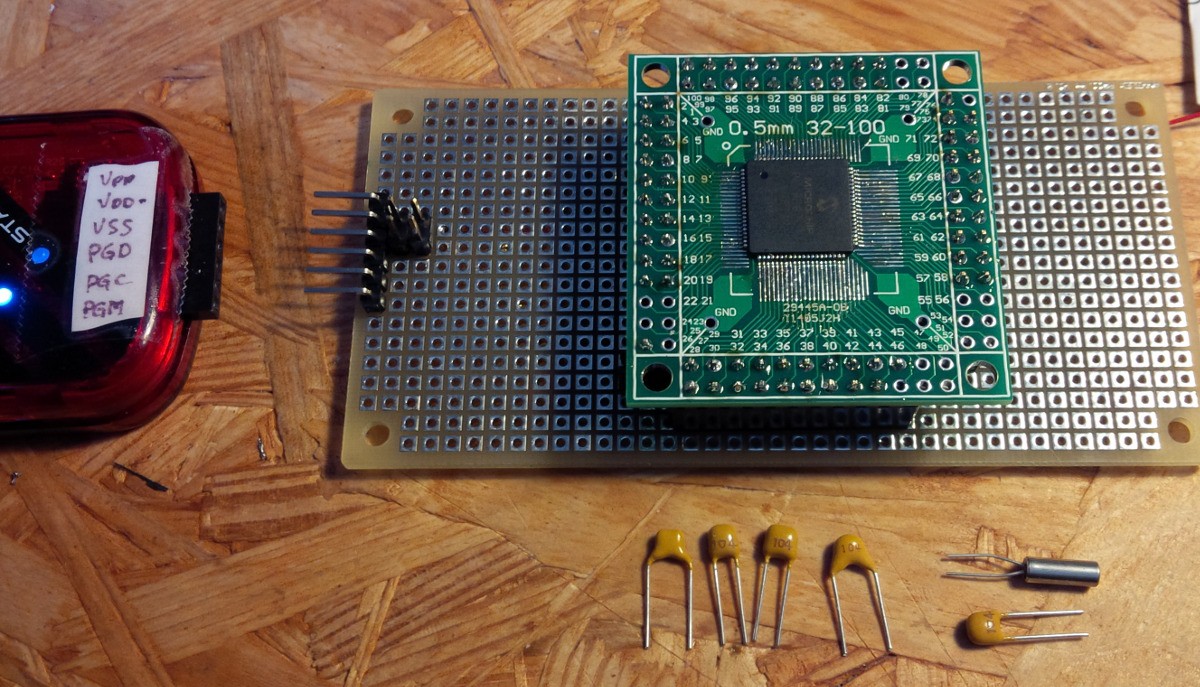
    I finally manage to solder the TQFP 80 package of the PIC on the breakout board. Everything seems alright, I can program the chip with the Pickit.


    It took me some time to figure out why the RTC was not working. I took a scope and checked the 32.768KHz second external oscillator, and could see a sine wave appearing. And that was the point. The signal appears when I put the scope probe on the quartz pin. The error was a wrong capacitor value. Somehow I put a 100nF cap instead of a 12pF for one of the quartz surrounding grounded capacitors. I don't know how the probe change the circuits impedance and makes it start oscillating, but with the correct capacitor I could now see the RTC running.

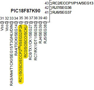
    A nice thing with the PIC 18F87K90 (let's call it the PIC...) is it can drive 48 LCD segments in static. Which is exactly all the segment I have on the 6 panels. 7 segments for the character and one dot. But... and it seems there is often a but with Microchip... But on the 48 pins able to drive LCD segments, one is multiplexed with the RTC oscillator... (pin 35 mixed SOSCI and SEG32)

    pin 35 mixed SOSCI and SEG32

    Well, I decided to get rid of one dot ;)

    Right now I connected 2 digits and they display the seconds of the RTC. It's working great however I should wait all segments are connected. I'm sure I will have to fine tune the Pic parameters to have nice contrast. After that, perhaps there is nice digit transition to make ? In addition, I have to think of time adjustment buttons.


View all 4 project logs

Enjoy this project?

Share

Discussions

greenaum wrote 02/26/2016 at 12:00 point

It's a handsome clock. One little note, NiMH batteries have quite a high self-discharge, so they'll probably be dead in a month, whether you used them or not. A set of alkalines would probably last ages. You can get small, low-power regulators, or just use the voltage drop from a couple of diodes. 

  Are you sure? yes | no

Muth wrote 02/26/2016 at 14:07 point

Thank you very much for your nice comment ! It's a good advice about NiMH, I don't have experience at all with them. And the diode voltage drop is very clever as well, I never though to use this trick.

  Are you sure? yes | no

Similar Projects

Does this project spark your interest?

Become a member to follow this project and never miss any updates