People asked me how to assemble the keyboard. I am planning to shoot a new assembly video as soon as I can, but until then...
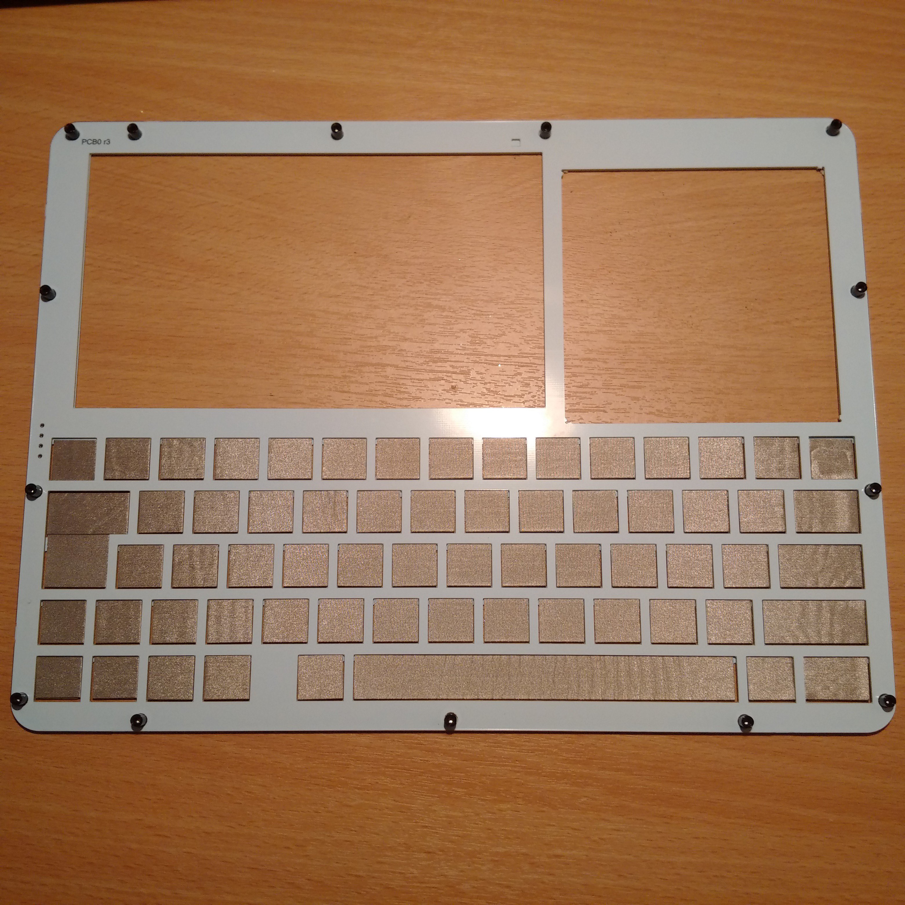
The self-adhesive pads supplied with ELLO are mean to go on the back side of the front board (called Panel). The assembly of the machine ALWAYS starts with attaching the fourteen standoffs to the front panel. Make sure you also remove the lid covering the prototyping space. You can either carefully snap it off, or cut the holding pieces using sharp cutters.
The place the panel face down (the standoffs will tall up), and start inserting the other PCBs in thus formed frame. The first one to go next is PCB0. Just like with the panel - if there is a lid covering the prototyping space, just snap it off or cut. Round up the remaining stumps a little bit, if necessary.
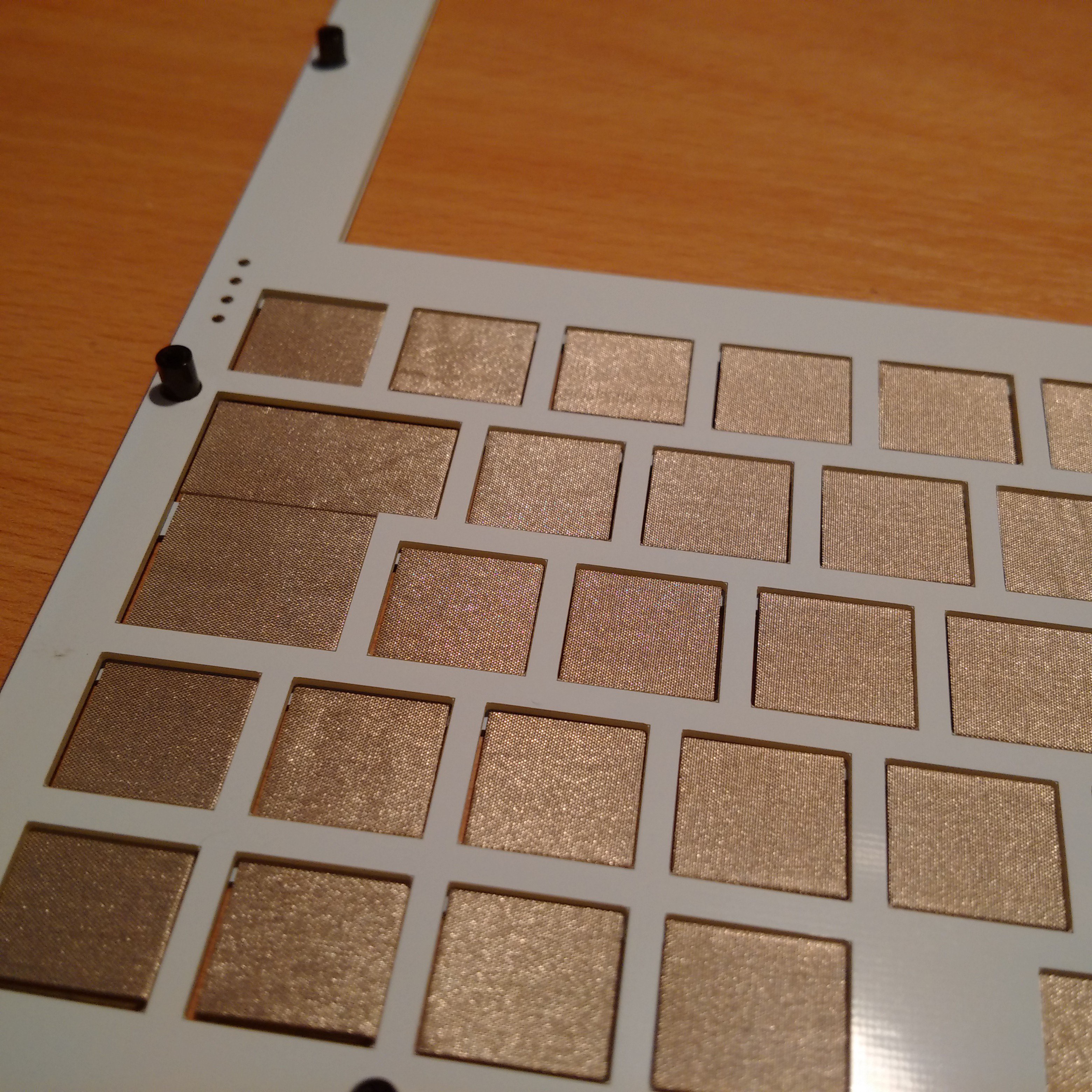
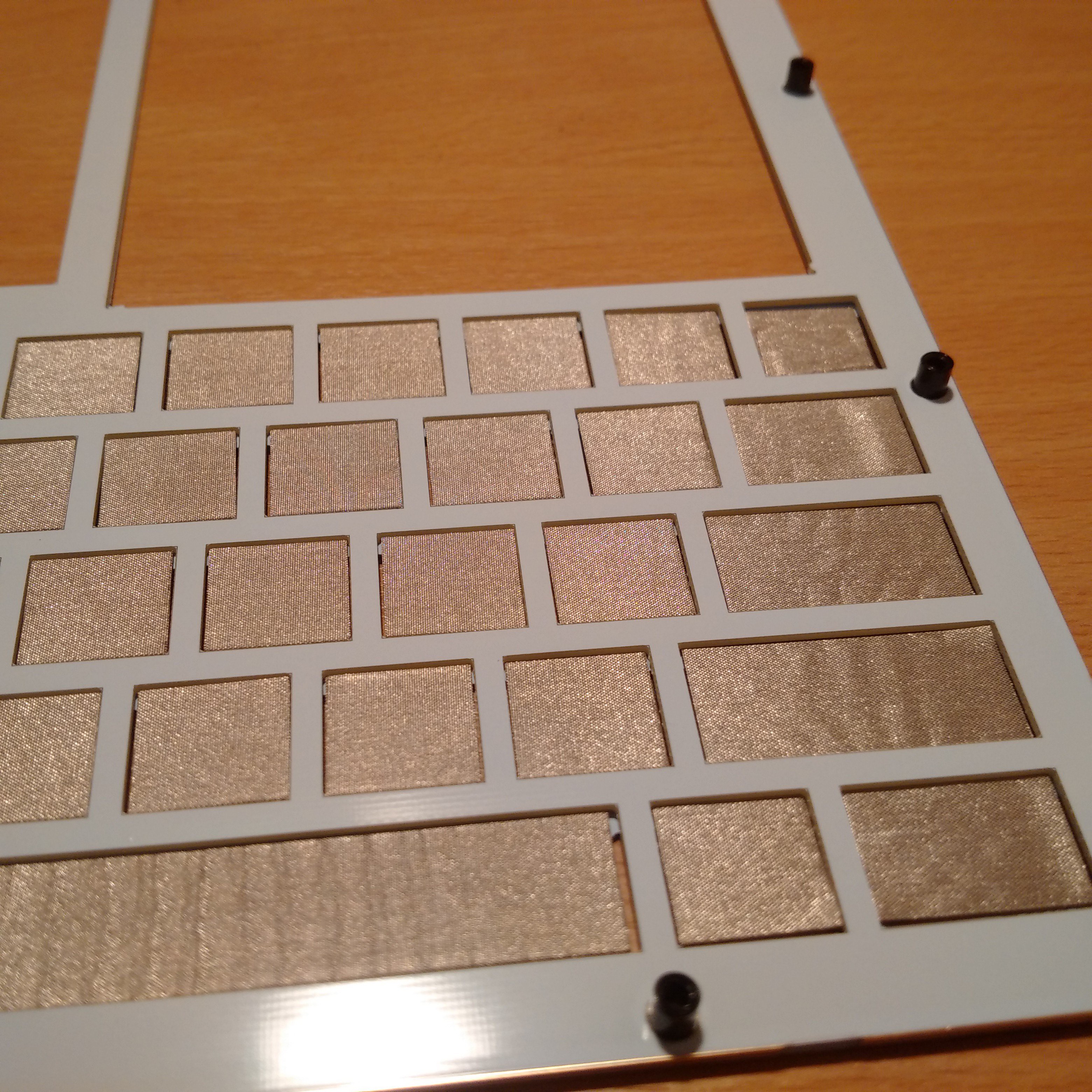
When PCB0 is in the stack, NOW is the time to put the patches. Carefully stick all of them in their places using the top line as reference.
Here is how the frame looks after the operation


Again, use the top line as reference, i.e. insert a patch into its frame until it hits the top and then stick. Thus you will guarantee that the keys are moving freely in their frames.
After patching the keyboard, the next to follow is the computer's main board - PCB1. Place it face down (components must be facing up).
Next - install the display panel face down in its place, and connect it to the connector on PCB1. Stick one of the two supplied round 3M double-sided adhesive patches on the back of the LCD (don't remove its top cover yet).
Stick the second 3M patch somewhere in the in centre of large black area marked for the battery. Remove the top cover as well. Then connect the battery (make absolutely sure that red wire goes to the contact marked '+', and black wire goes to the contact marked '-'). Then carefully stick the battery on the 3M patch in such way that it does not extend over the boundaries marked with lines on PCB1. Tidy up the battery wires so they don't go over the display cable, but around it. With poor assembly you might experience poor picture on the screen as well due to noise, so this is pretty important, actually.
Now install PCB2 again face down. The prototyping sockets must go in their spot. If they can't, that means there is a stump remaining on PCB0. Round it up a bit more and then install PCB2.
PCB3 follows next.
Now it is the time to remove the top cover from the 3M path that is already stuck on the back of the LCD. But don't do that yet, and do this little trick instead.
Install the final PCB4 and screw in the bottom two corner screws so it is fixed in its place. Now bend the top side slightly up to reach under it and remove the top cover from the 3M patch which is on the LCD. Carefully release the board back in its place and screw in tightly all screws.
Your new ELLO 2M is ready to dance.
 Kn/vD
Kn/vD
Discussions
Become a Hackaday.io Member
Create an account to leave a comment. Already have an account? Log In.