Close
0%
0%

T85 Target

A mini Attiny85 target dev board

Similar projects worth following
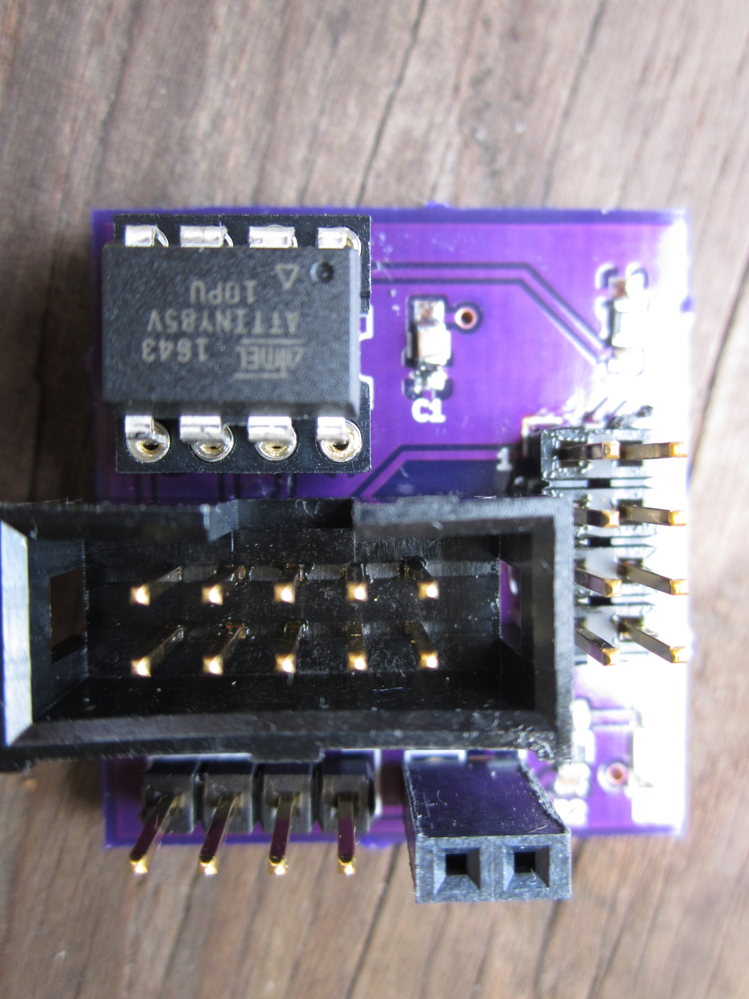
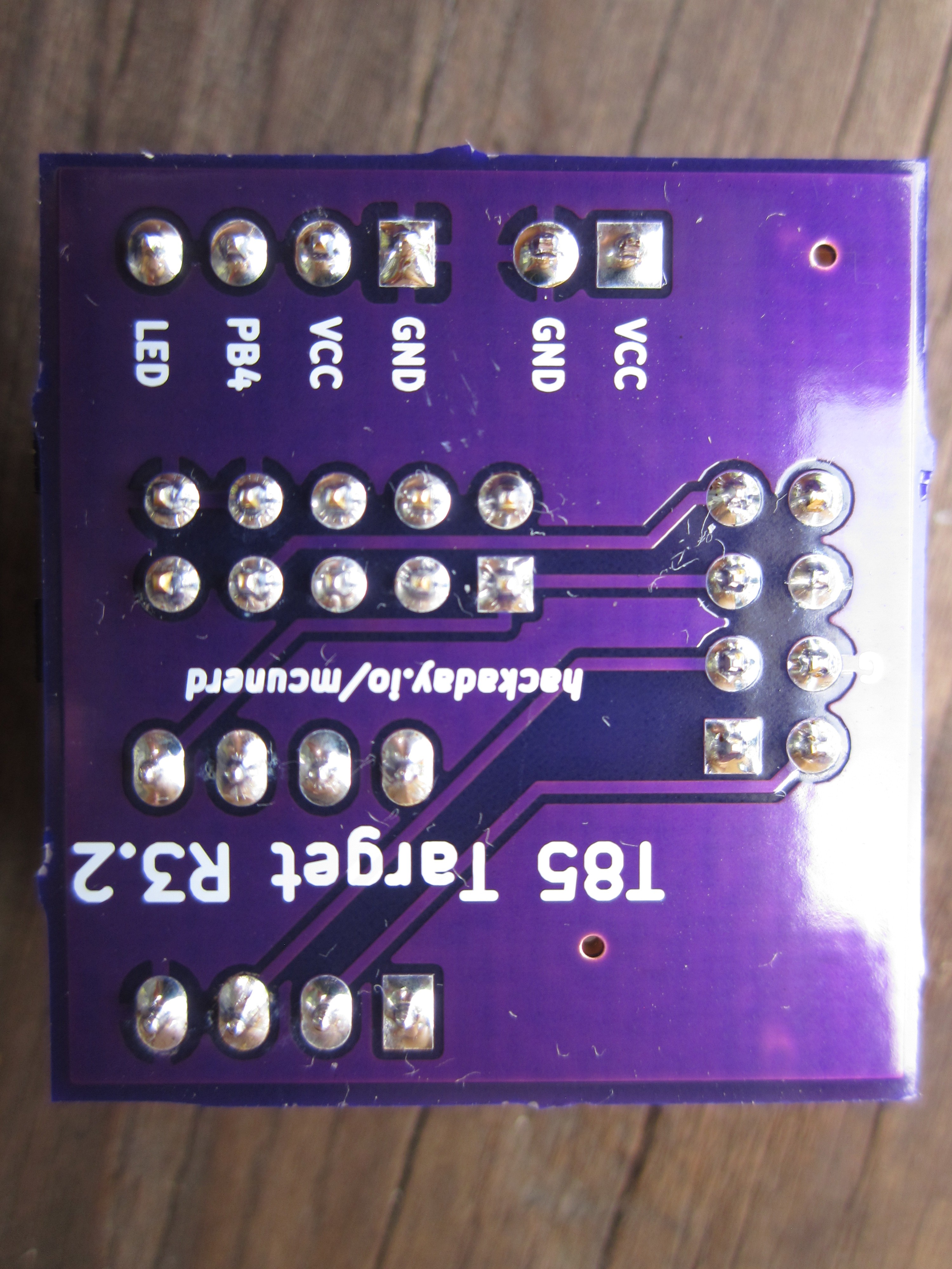
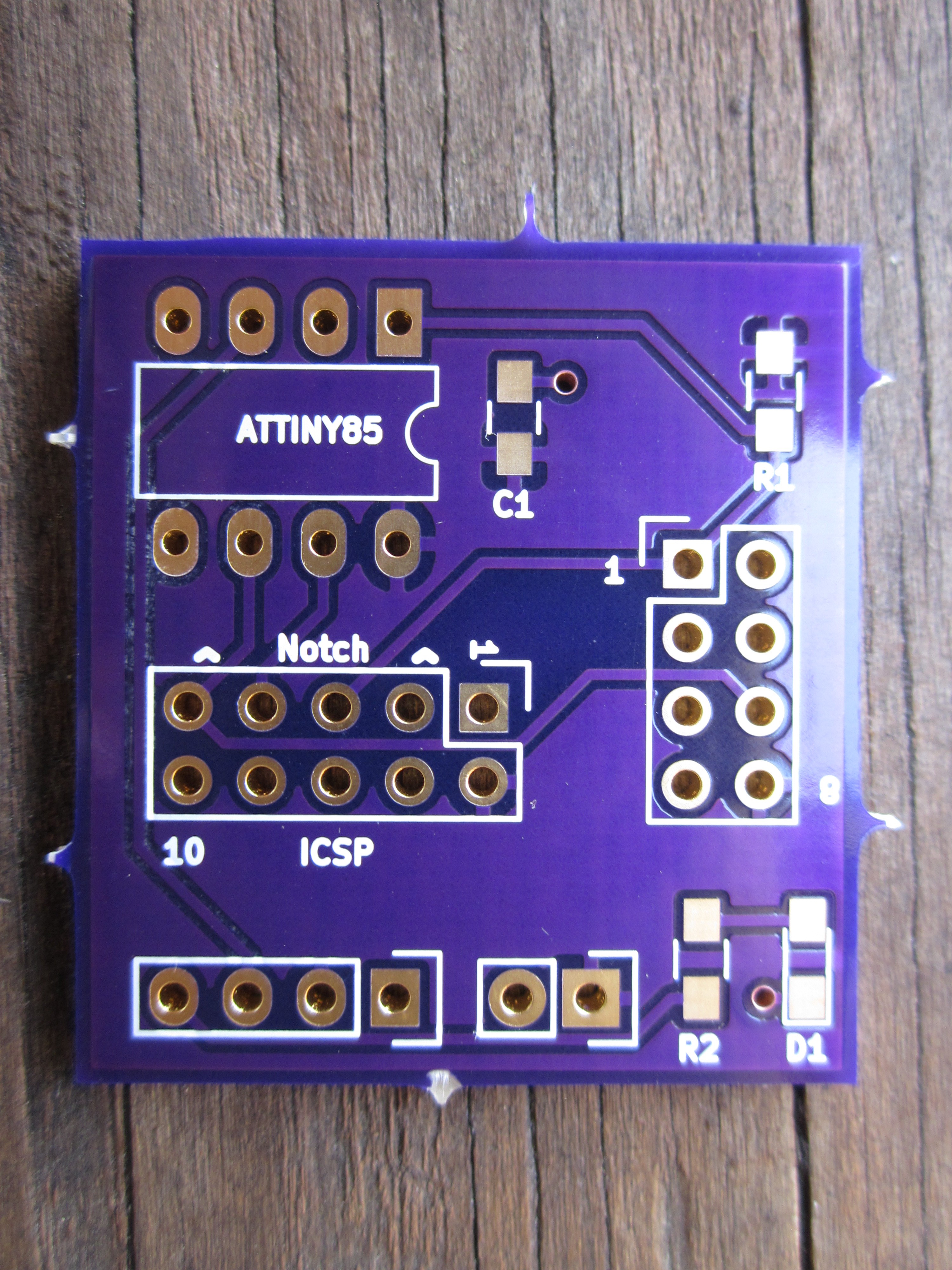
I started this small project after I saw there there weren't many Attiny85 development boards out there. I've went thru several design revisions in an effort to balance functionality/price. The current revision uses a 10-pin ICSP header for using a cheap USBasp without having to use a 10-pin to 6-pin adapter. I also decided to try my hand at some surface-mount components and the current revision uses 2 SMD resistors and a capacitor.

Features:
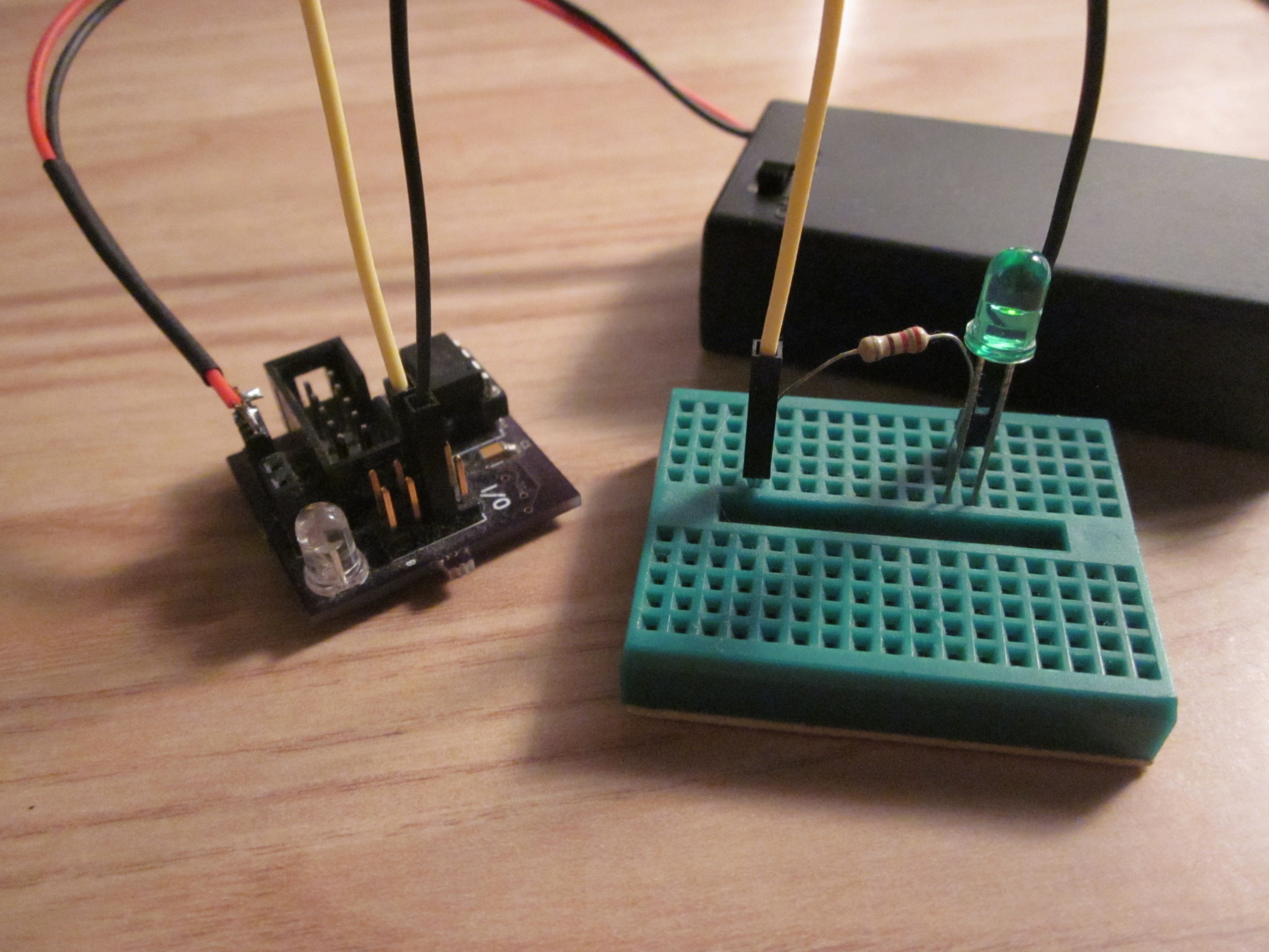
An LED (because every dev board has to have an LED to blink!) that can easily be connected to PB4 of the Attiny with a jumper

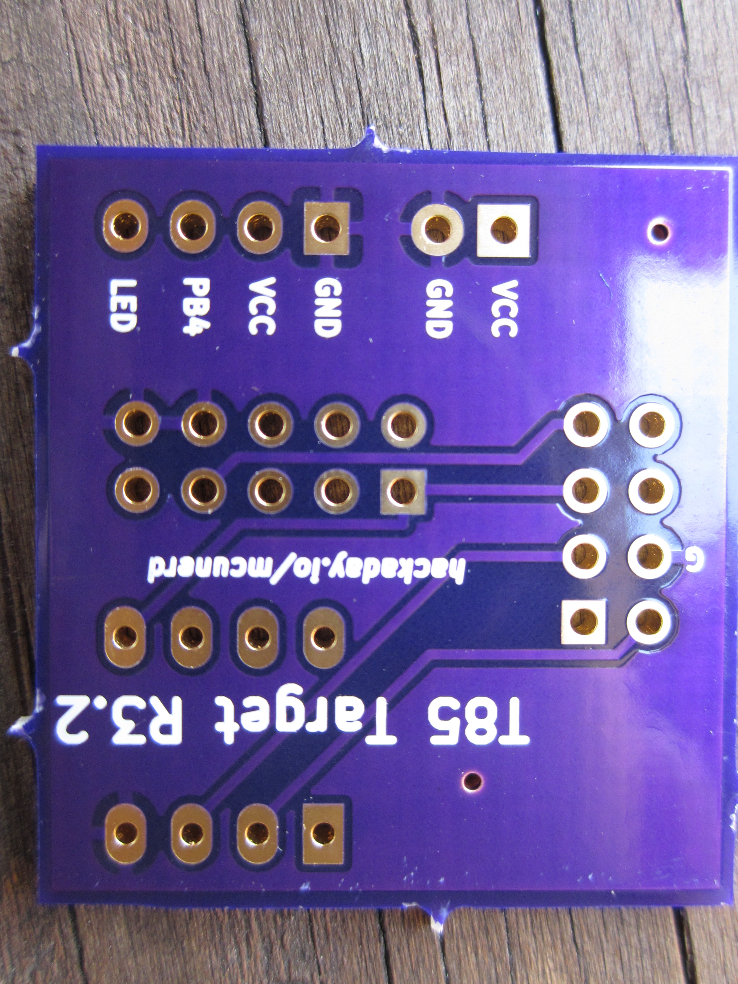
A redundant set of power pins(one with male pin headers, and another with female pin headers) for powering it with a power supply/battery

A DIP socket for the Attiny85 and of course a pin header that breaks out all of its pins.

I set out to do this mini project as I was tired of having to plug in individual wires from my USBasp to program the darn thing. I've done a few revisions, with revision 1 and 2 including a power supply but decided against it for the third revision to save on board space. I'm for the most part happy how the third revision came out in comparison to the first two revisions. I switched to surface-mount components for the resistors and capacitors to save a little on space, it looked nicer to me, and to see how easy/hard surface mount components are to work with.

Getting the surface-mount components soldered proved to not be a difficult task. Previous to the third revision, I avoided using surface-mount components in my designs for fear it would be a nightmare to solder. If anything, this project has made me more open to using surface-mount components.

I made a separate board to mount a 5v regulator on with a barrel jack to make use of the many wall warts that I have laying around. I found this to be a more flexible solution as that can be used for powering other circuits. If anyone is interested in that board, I'll be happy to post that micro project.
t85targetr3.2.zip

The latest revision of the board. Includes both the KiCad files and the Gerber files.

x-zip-compressed - 113.81 kB - 08/23/2019 at 21:55

Download

t85lightning.zip

artificial lighting bug/firefly

x-zip-compressed - 9.33 kB - 08/29/2018 at 15:24

Download

t85lightning_128KHz.zip

artificial lighting bug/firefly with a system clock of 128KHz for lower power consumption (will need to change fuses to set clock to 128KHz)

x-zip-compressed - 9.45 kB - 08/29/2018 at 15:24

Download

  • 1 × ATtiny85-20PU Microprocessors, Microcontrollers, DSPs / ARM, RISC-Based Microcontrollers
  • 1 × 8-pin DIP socket
  • 1 × .1 uF 1206 SMD ceramic capacitor
  • 1 × 220 ohm 1206 SMD resistor resistor for LED
  • 1 × 10k ohm 1206 SMD resistor pull-up resistor for the attiny

View all 11 components

  • I admit it, I have a problem . . .

    mcu_nerd08/23/2019 at 21:56 0 comments

    . . . with always wanting to tweak my board designs.  

    Anyways I made a few changes.  I've went from 1206 to 0805 for all the surface mount passives.   The on-board LED is now surface mount.  Voltage and ground planes were added.  Auto routed races were re-done with manually routed traces.  It was a bit of a puzzle of tweaking the layout and trace placement to get good coverage of the voltage and ground planes. I've posted the updated KiCad and Gerber files.

  • Another fun little project

    mcu_nerd08/29/2018 at 15:23 0 comments

    My latest use for the board is using it as an artificial lightning bug/firefly of sorts in terms of a flickering light. I was originally running the Attiny85 at 8 MHz.  The average power consumption was a little bit over 3 mA, but seeing as I was running it off a pair of AA batteries I wanted to see if I could do a bit better.  

    I looked up the typical power consumption curves on the datasheet and by switching to using the 128 KHz oscillator dramatically lowers the power consumption a bit.  I did so (and also disabled the analog compactor and got power consumption down to I'd say a little bit over .5 mA.  I though about clocking it down to 16 KHz but the ADC wouldn't operate with a clock that low (using the ADC for random number generation.)  Even if I could keep the ADC running with a 16 KHz clock, it would likely provide little improvement as the LED itself would become the major bottleneck. 

    I'll post the files for both the 8 MHz and 128 KHz variants.

  • It's the clock that's the problem, or is it? (yet another followup on the servo issue)

    mcu_nerd02/08/2018 at 22:59 0 comments

    Up until yesterday, I thought the issue with trying to control the MG90S servo was the internal accuracy of the Attiny85 rc oscillator being too poor.  

    Yesterday, I was trying to control the same MG90S servo with a board that I'm developing.  That particular board, unlike the T85 target board has the option to add an external crystal (which I used.)  Had the exact same problem! It was not working at all/unstable.  I then tried to control the servo with my Arduino Uno, and it worked perfectly fine.  

    I initially blamed the the cheap Ebay crystal when according to the frequency measurement function of my EX330, it appeared that the accuracy of the crystal was worse than the Arduino Uno that uses a resonator (the mulimeter's frequency measurement function really isn't accurate enough for the task, but it was all I had/still have.) I managed to find some crystals that I ordered from Mouser some time ago and used one of those.  Same issue.  I compared my board to the Arduino Uno and noticed that the Uno has some electrolytic caps on it's 5V rail.  This had me thinking. Could it be a frequency accuracy issue, or is it really a power/noise related issue?

    I decided to try my revised hypothesis by bodging in two 47 uF caps in parallel, and servo control was working much better with some occasional glitches.  I then decided to hook up the servo more directly to the power supply and it works flawlessly!  A little bit ago I decided to try the solution on my T85 board and the servo also works fine.  

    So the problem appears to be that unlike my other servo, the MG90S must draw more current thus creating a greater voltage sag, thus crashing the mcu, resulting in having issues controlling the servo (found out that the servo was causing the mcu to crash after a bit of probing with my mulimeter.)  The solution is to give it a more direct connection to the power supply vs using the servo header.  A large enough electrolytic capacitor on the board should also fix things.

    Other interesting bits:

    I noticed that with the board I"m developing the servo would often crash the mcu in various interesting ways.  Sometimes the 50Hz signal would go completely missing.  Other times the duty cycle would remain static.  The most interesting failure mode was when the duty-cycle output became inverted.  I did try using a watchdog timer to reset the mcu after it crashed, but even that wouldn't work (even after I removed the servo.)

    TL,DR

    It has nothing to do with the accuracy of the 50Hz signal, it was simply drawing enough current to cause a voltage sag that made everything unstable.  Solution:hook it's power pins more directly to the power supply vs using the servo header.  A large enough electrolytic capacitor on the board should also fix things.

  • Thoughts on creating yet another revision with a crystal oscillator

    mcu_nerd11/14/2017 at 17:16 0 comments

    Yes, I'm mulling over the idea of creating yet another revision.  The problem with getting digital servos to work reliably due to the internal oscillator not being stable enough could be solved using an external crystal but a drawback is that it would consume 2 I/O pins which is a big deal as there are few I/O pins to begin with.  I've seen those 4 pin surface-mount crystal oscillators that would only require 1  I/O pin.  I'm looking for an 8 MHz one that could work at both 3.3V and 5V, so if anybody has any suggestions please be sure to post a comment.

    I've since become more convertible with manual routing traces with more recent projects, so the next revision would have manually routed traces. I would also probably do a ground plane as well. I could change the ICSP header from 10 pins to 6 pins to save board space but I do like being able to plug in my USBasp without needing an adapter.

  • Got extremely close to 50Hz but still not good enough

    mcu_nerd02/12/2017 at 17:24 0 comments

    This is a followup to An update on dealing with Servos post. I wanted to take another shot of getting close to 50Hz as I could in order to actually get my pesky MG90S digital servo to work.

    I decided to calibrate my Attiny85's internal RC oscillator. On page 164 of the Attiny85 datasheet it mentions that Atmel calibrates them at 3V. Mine was running at 5V, so there was room for improvement. I didn't have any really fancy frequency measurement tools, but I did have my EX330 multimeter that has a frequency measurement function.

    The first thing I needed to do was to get the current calibration value as a starting point. The calibration value is stored in the OSCCAL register. The second question was how to read that value from my Attiny85. I could hop into the Arduino IDE and use the software serial library, but that would also mean that I would have to dig out my usb-serial converter.

    A more convenient way that requires no additional hardware is to write the value stored in the OSCCAL register to EEPROM and then use AVRDUDE to dump the EEPROM contents. The subroutine to write a value to EEPROM is very simple (yea I pretty much ripped it off from the datasheet):

    void writetoeeprom(int addr,char data){
    while(EECR & (1<<EEPE));
    EECR = (0<<EEPM1)|(0<<EEPM0);
    EEAR = addr;
    EEDR = data;
    EECR |= (1<<EEMPE);
    EECR |= (1<<EEPE);
    
    }
    

    So now we just place the value from the OSCCAL register into a variable and use the above subroutine to write it to the first byte of EEPROM:

    data = OSCCAL;
    writetoeeprom(0,data);

    After we upload the program which contains the above, we can dump the EEPROM with AVRDUDE:

    avrdude -p t85 -c usbasp -U eeprom:r:text.hex:i

    We then look at our dump file and look at the first byte that comes after ":20000000" and convert that hex value to base 10.

    When I did the above I got a value of 137.

    Next step was to generate a clock signal on a pin. I chose to use PWM to output what's supposed to be a 1Mhz signal on PB4 and ajusted the value of the OSCCAL register untill I got as close as I could get:

    DDRB |=0b00010000; //set pin3 PB4  for output as first step for pwm 0c1b
    TCCR1 |=0b10001011;//set up pwm prescaler
    GTCCR |=0b01100000;//enable pwm 
    OCR1C= 8-1;
    OCR1B=4;
    OSCCAL=131;

    After doing all of that I set PWM frequency back to 50Hz and measured it. It was off by a few hundredths off normally but there was also some jitter. I looked up the digital servo and it failed to work correctly. The darn thing wants 50Hz period not 50.04 Hz or such. An important note that setting OSCCAL to a different value does not permanently change the factory calibration, if the OSCCAL line was removed, it would run at the fectory calibrated value instead.

    In conclusion driving digital servos with the Attiny85's internal RC oscillator is a crapshoot. Having to use a crystal may be the only solution. I went against putting a crystal on my T85 board as that would have taken 2 I/O pins and the the Attiny85 only has 5 I/O pins to begin with (in some circumstances you can use pin 1, giving you six.)

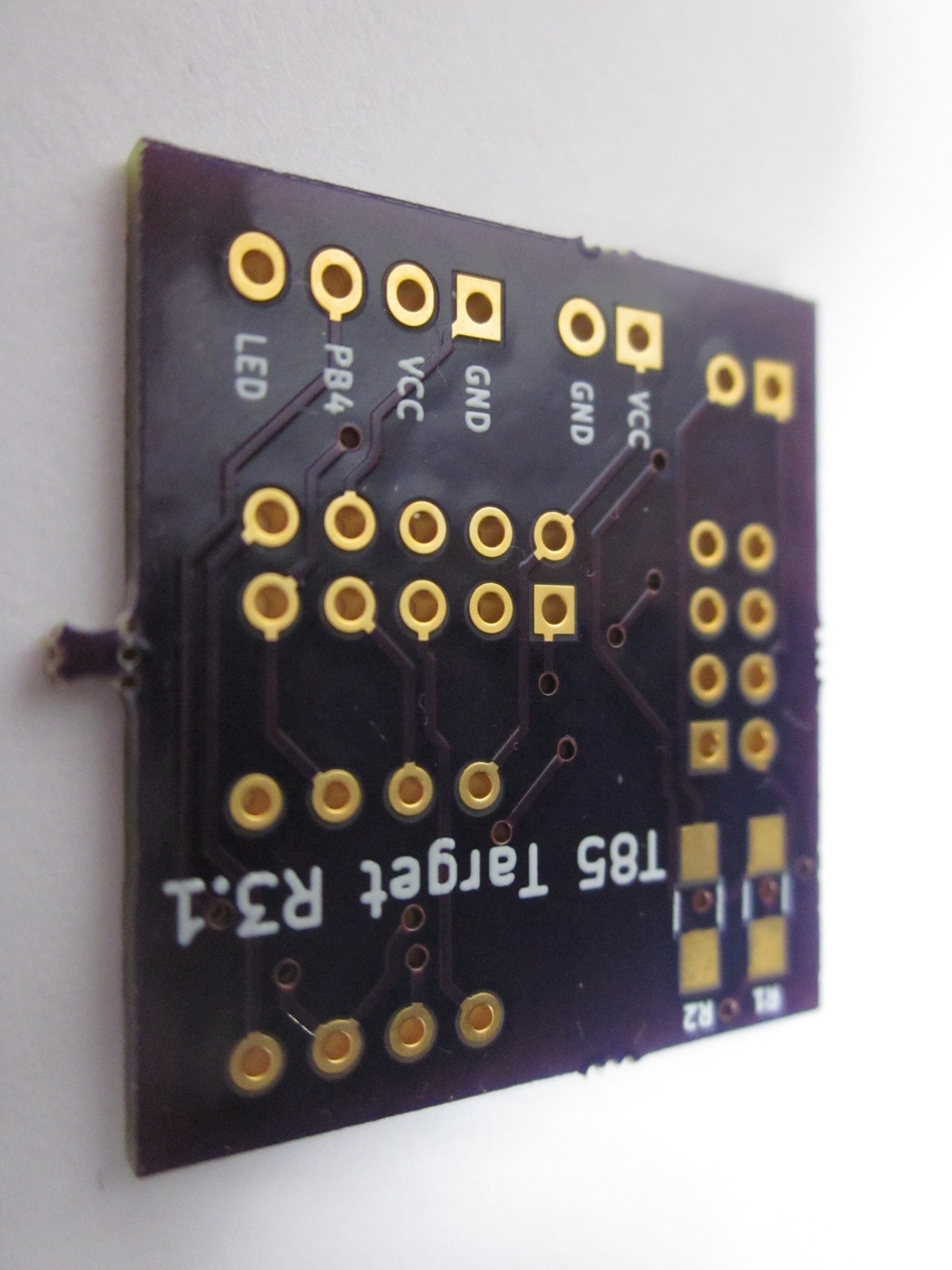
  • Say Hello to Revision 3.1

    mcu_nerd05/31/2016 at 23:17 0 comments

    I assembled up the new board this morning, and so far everything is working great. I moved around some of the labeling to make it easier to read and I flipped the ground and VCC pins on the single row male header to allow one to directly plug in a servo into the board. I would only recommend plugging only micro servos directly into the board, anything larger would most likely require a separate power supply.

    The updated KiCad board files have been posted to GitHub and I've updated the servo demo for use with the 3.1 board. I did take another shot at trying to get my MG90S servo with it, but no such luck; it really does want the PWM frequency at exactly 50 Hz. I did later learn that unlike the SG90, the MG90S is a digital servo which may explain why it's so picky.

    For soldering components on the board I decided to stick to just using .020" Kester 44 63/37 for everything as opposed to using the .020" solder for just the surface mount components and using .032" AIM 63/37 for everything else that I've done on past boards. I got much nicer joints compared to using the .032" AIM solder for the thru-hole parts, I'm not sure if it was due to the diameter difference and/or brand difference.

  • Look at what came in the mail during the weekend

    mcu_nerd05/30/2016 at 13:54 1 comment

    Got these boards in the mail on Saturday. I shall pull out the soldering station tomorrow and assemble one. I'll post the board files once I see that all is well. Happy Memorial Day!

  • Future revision plans

    mcu_nerd05/13/2016 at 15:01 0 comments

    Yes, I will be making yet another revision. Current planned changes include flipping the Ground and VCC pins on the single row male header to allow one to directly plug in a servo into the board. I also plan to flip the labeling on the single row male header to the other side of the board for easier reading.

  • The board not only works with Attiny85 . . .

    mcu_nerd04/13/2016 at 12:44 0 comments

    When I created this board I had the Attiny85 in mind as the Attiny85 has a very nice 8 KB of flash for its small pin count, but it also works with the Attiny45 and Attiny25. It should also work with the Attiny13/13A but it doesn't have PWM available on PB4 so if you want to send a PWM signal to the on-board LED, you will have to remove the jumper and hook the LED to another pin.

    So why would you want to use one of the lower-end Attinys? Price. If you plan to make a product that uses an Attiny that you plan to produce a substantial quantity of and your code is able to fit within the 1 KB of flash/64 bytes of RAM of the Attiny13A it looks quite appealing as the Attiny13A can be had for ~$0.60 USD or less if you shop around.

  • Demo series: RGB LED demo

    mcu_nerd04/11/2016 at 17:46 0 comments

    Today on the demo series is using the Attiny85 to drive a common anode RGB LED. I did this example under the Arduino IDE. I included two versions: A very basic one that just instantly rotates thru a few colors and rgbv2 that makes fade transitions between colors.

    To find these demos, just click on the GitHub reporisotry rank on the project page.

View all 13 project logs

  • 1
    Step 1

    Start off with soldering the surface-mount components first (recommend using .020" diameter solder.) Solder the 10K ohm resistor on R1, the 220 ohm resistor on R2, and the .1 uF capacitor on C1.

    Of course, solder the rest of the components to the board.

  • 2
    Step 2

    For cleaning, use 91% (or higher) isopropyl alcohol and a toothbrush (or some other clean non-metallic brush.)

  • 3
    Step 3

    Check for any short circuits after the board is dry.

View all 5 instructions

Enjoy this project?

Share

Discussions

Similar Projects

Does this project spark your interest?

Become a member to follow this project and never miss any updates