 SHAOS
SHAOS1st board for this project is NEDONAND-1 that is 1-bit slice of NEDONAND ALU:
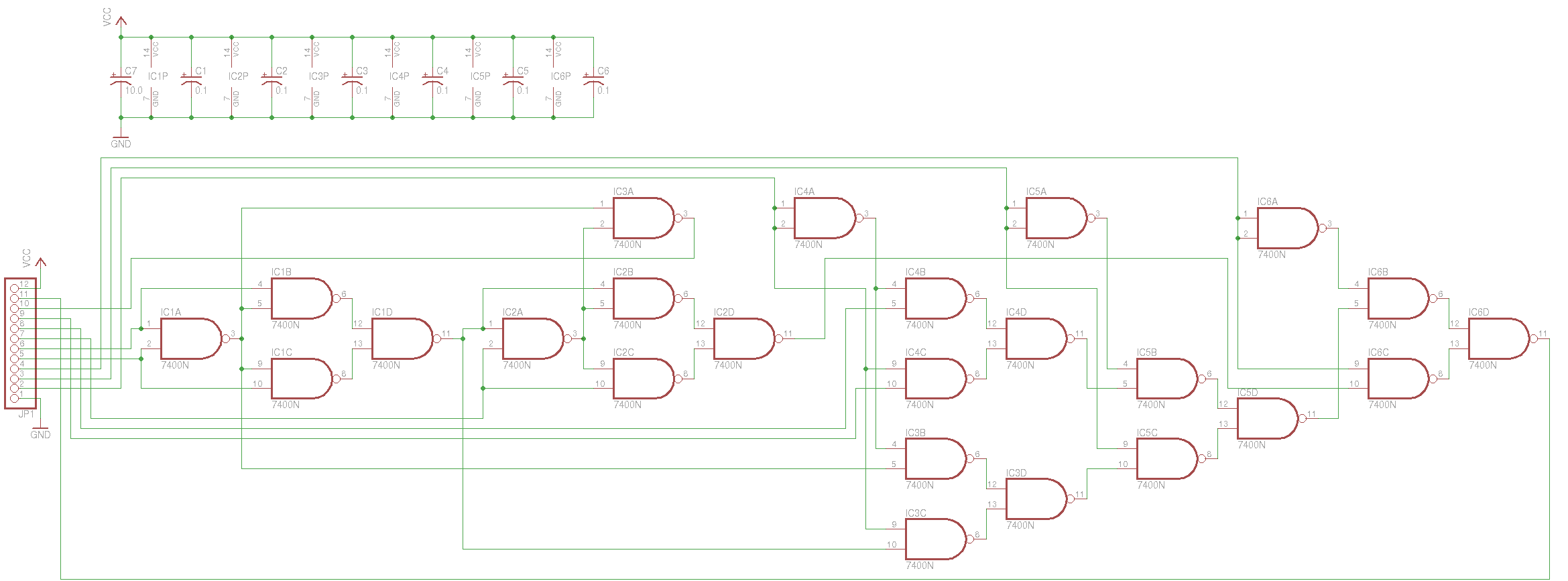
Pins description:
1) GND - ground;
2) O0 - bit 0 of ALU operation;
3) O1 - bit 1 of ALU operation;
4) O2 - bit 2 of ALU operation (if it's "1" then O0 and O1 are ignored);
5) A - input bit A (always from accumulator);
6) B - input bit B (might be from register or number);
7) C - input bit C (carry);
8) H - higher bit for rotation right;
9) L - lower bit for rotation left;
10) COUT - carry out;
11) DOUT - data out;
12) VCC - power +5V.

Discussions
Become a Hackaday.io Member
Create an account to leave a comment. Already have an account? Log In.
no yet - only functional testing
Are you sure? yes | no
Now that makes sense :-) Did you check how fast it works ?
Are you sure? yes | no