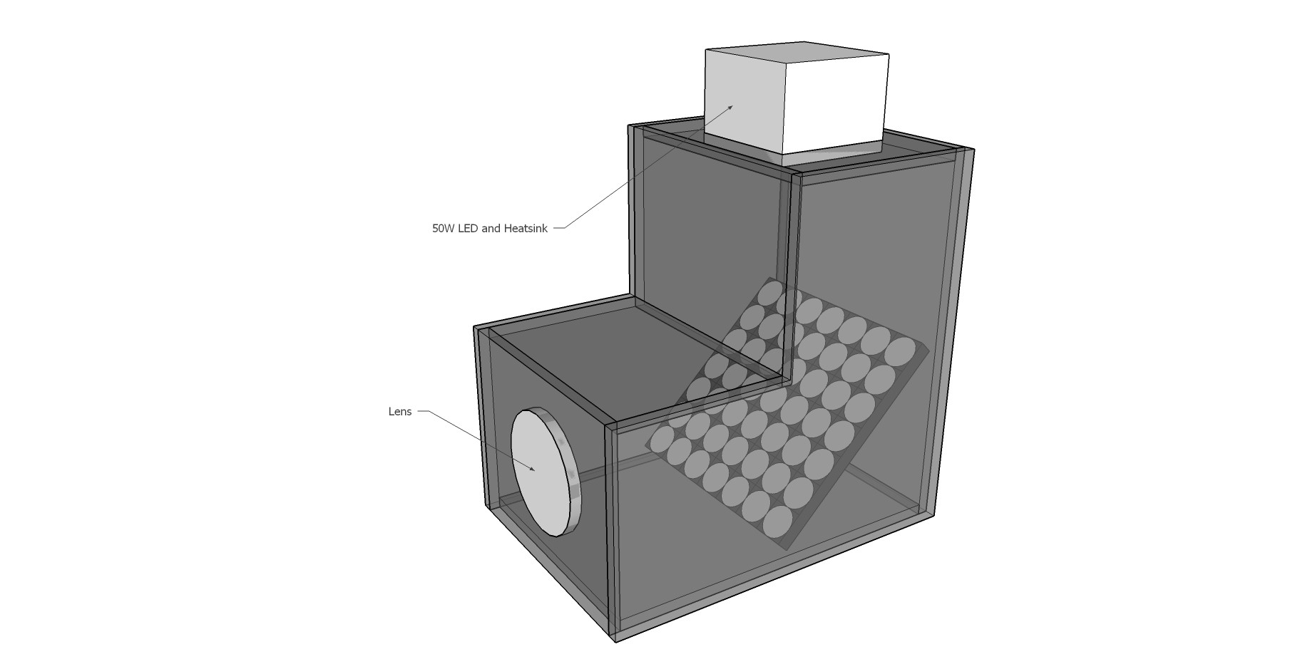
Above is an initial sketch of a top mounted LED light source, 45 degree angle flip-dot mirror display, and a lens. Tests with a 50W LED were not successful, nor was use of a lens (at least one I had on hand) after the light hit the flip-dot display. It worked much better to have a focused beam bounce off the dots, putting the lens between the LED and the display.
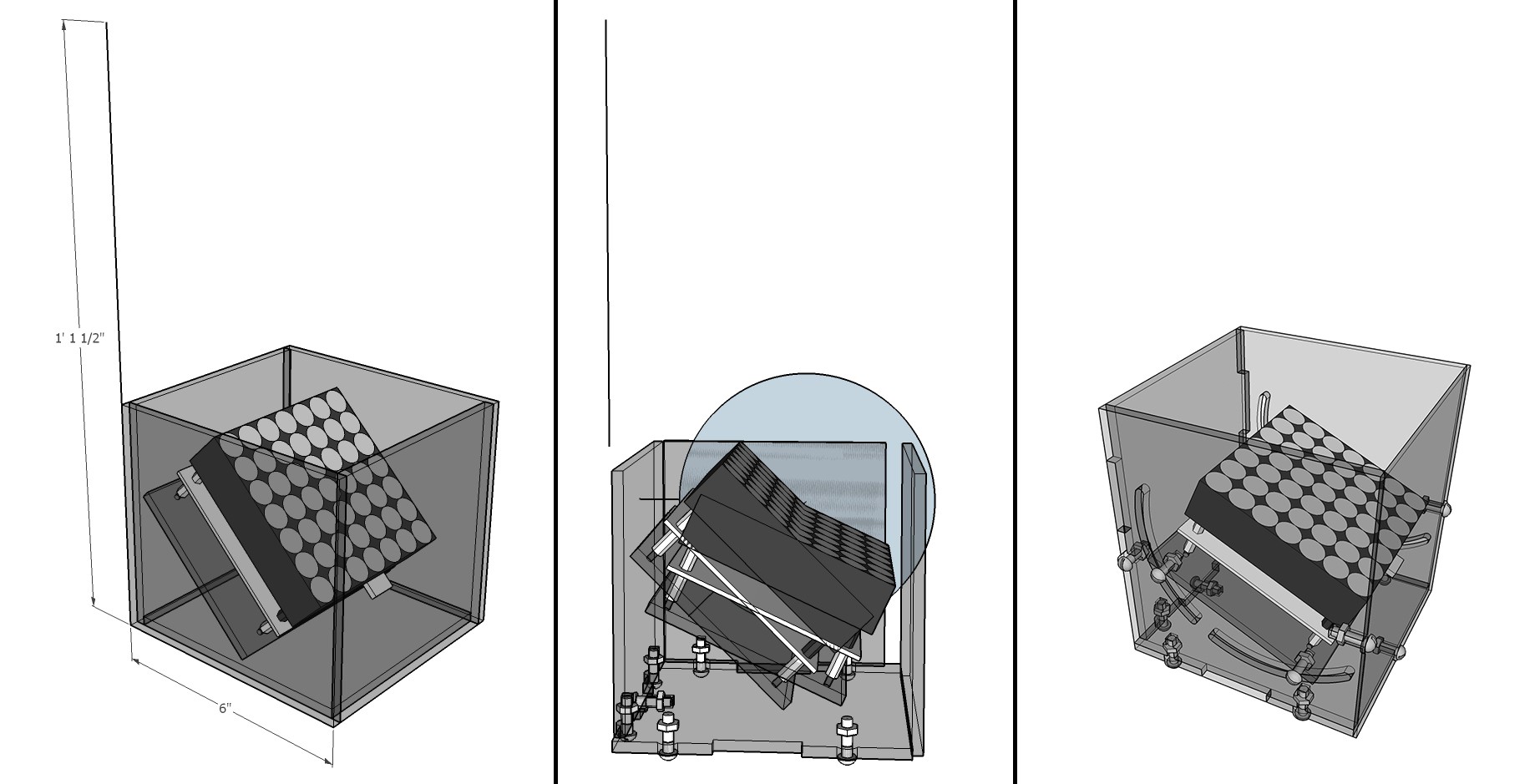 Above are 3 steps of working out how tight the acrylic housing could be to the display, while still allowing for adjustment of its angle.
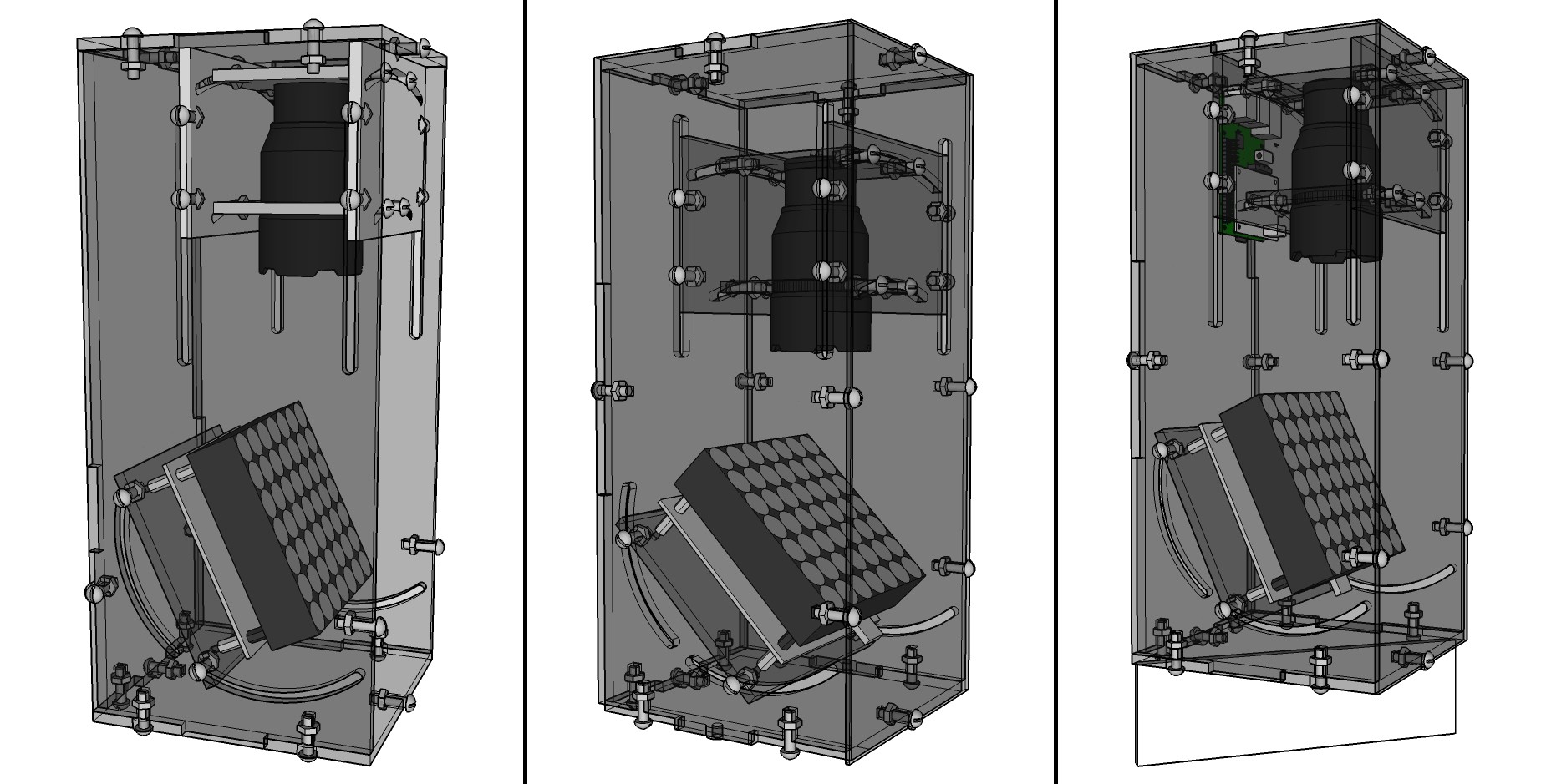
3 more stages of refinement of the model, adding the LED light source at a distance based on tests with the actual display and LED flashlight at a few focal lengths. These have an angle adjustment for the LED, centered on the display, because I noticed that the flip-dots don't lay completely flat and shifted the projected image off to one side.
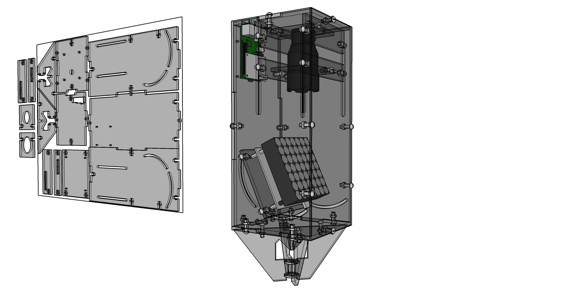
Above is the final model of the case, including a connection for a cymbal stand from a drum kit on the bottom. This version has a new vertical adjustment for the flashlight since it focuses by sliding the lens in and out and I'd forgotten to include that previously. To the left is a layout of all the components nested into an 18x24 sheet of acrylic (the size I could easily find at a local hardware store) with a few left over to add on another sheet.
Discussions
Become a Hackaday.io Member
Create an account to leave a comment. Already have an account? Log In.