 esben rossel
The latest firmware and PCB is here:
besides from being smaller, there's now a regulator on the supply voltage:
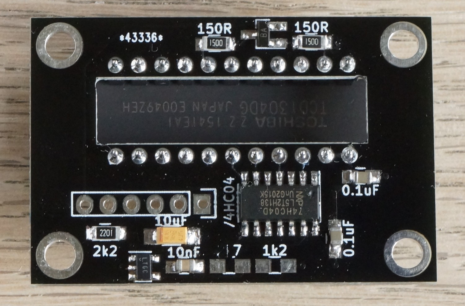
Vs = 1.22 (1 + R₂/R₁) = 1.22V(1+ 2.7kΩ / 1.2kΩ) = 3.96V
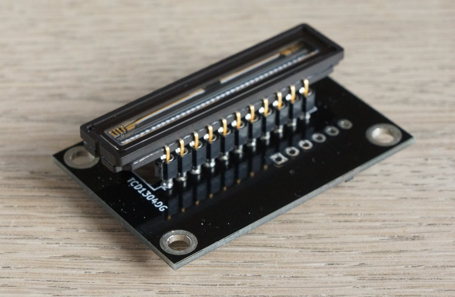
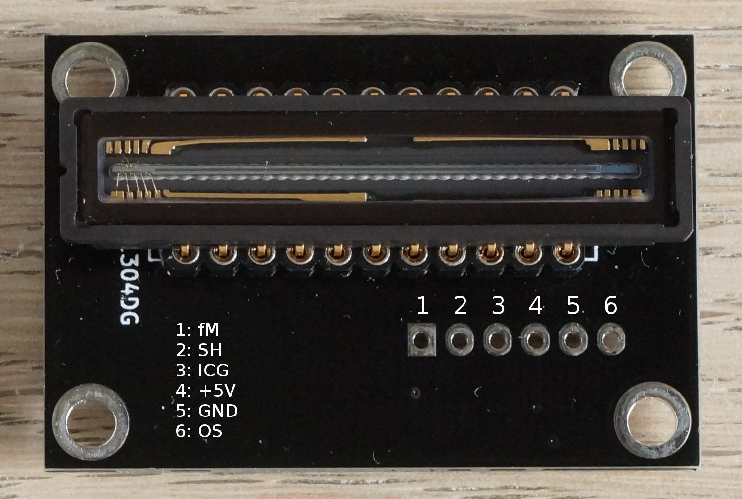
The pinout has been changed:
and so has the GPIOs on the STM32F401re, so everything's much easier to connect:
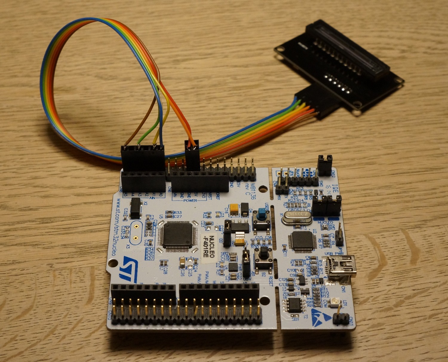
(The CCD-PCB in the picture is a prototype)
As always go to https://tcd1304.wordpress.com to be sure to get the latest and greatest firmware and software, and instructions to match.
The PCB (slightly improved compared to the one in these images) is available directly from http://dirtypcbs.com/store/designer/details/8475/6065/tcd1304-4vn-zip
It's only the UART-firmware that has been updated. The SPI-version will follow shortly.
Both firmwares (SPI and UART) been updated with the new GPIO-configuration:
- fM on PB0
- SH on PA1
- ICG on PA0
- OS on PC0
Discussions
Become a Hackaday.io Member
Create an account to leave a comment. Already have an account? Log In.