Russell Kramer
-
Rise/Fall control
03/11/2016 at 03:18 • 0 commentsWith the Zapper project I implemented a system where when the gun is pointed away from the screen or at a dark area the voltage stored in the holding capacitor can gradually rise, fall, or remain unchanged. I was initially planning to leave this out of the glove project, but changed my mind because the audio circuit (covered in next log) wasn't sounding very good and I hoped this would produce a big improvement. The audio does have a different sound now, but the graphics feel unresponsive when they're allowed to change without direct input from hand motions. I may reverse my decision and take rise/fall control out of the project later on.
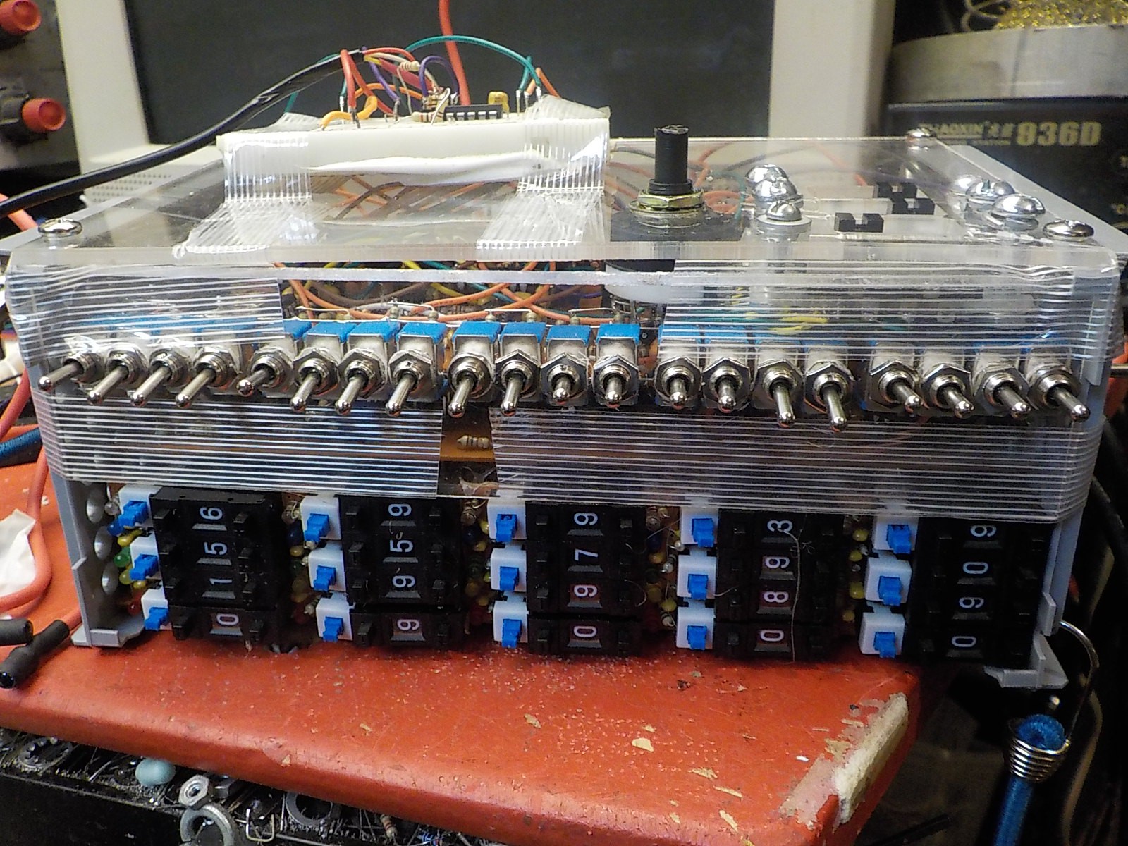
Last time I implemented rise/fall control with one potentiometer and one SP3T switch for each axis. With the glove project that would be ten potentiometers and ten switches for the five different X,Y values, so I changed the implementation. Now each axis is controlled by two SP3T switches which allow it to hold or rise and fall at three different speeds.
![]()
The row of twenty SP3t switches. Four per finger; two per axis. Audio circuit control is below the switches.
![]()
-
Video Circuit 3: Gradients
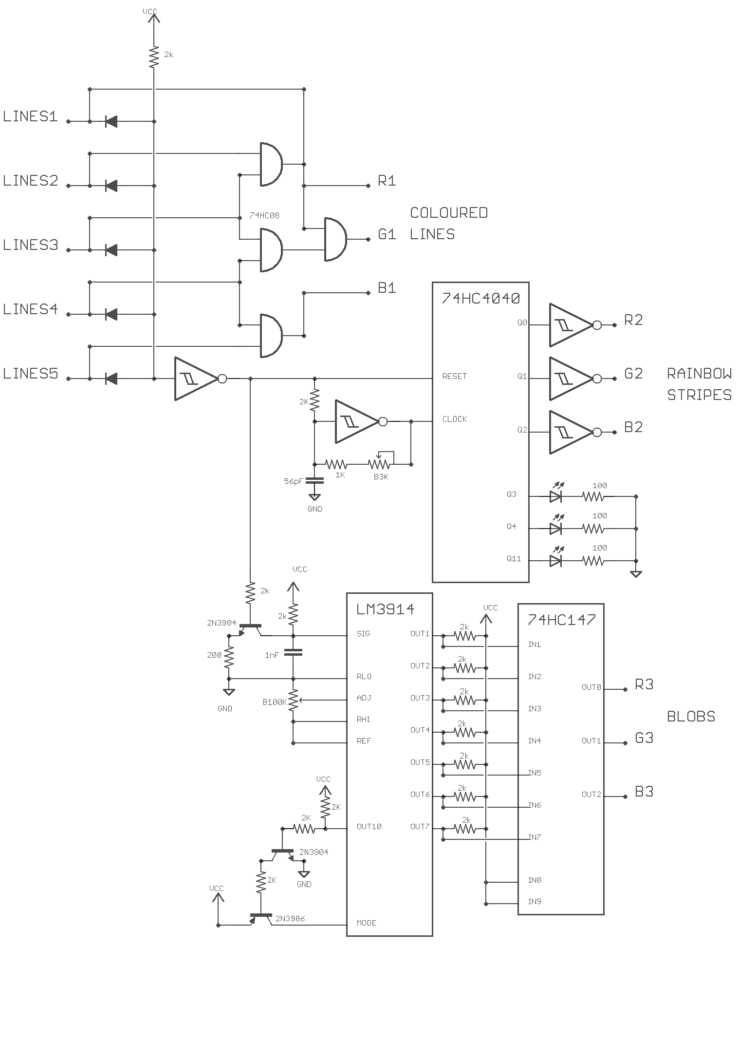
03/06/2016 at 02:58 • 0 commentsThe gradiant board takes the five warped line video signals , combines them, and uses the result to produce colour patterns.
There are three RGB outputs on this board:
Coloured Lines
Uses a 74LS08 (quad 2-input AND gate) to draw coloured lines on a white background. Each of the five line signals gets a unique color. Red, Green, Blue, Yellow, Pink. The screenshots shown in the last log entry were produced by this output.Rainbow Stripes
A 74HC4040 binary counter is clocked by a Schmitt relaxing oscillator controlled by a potentiometer. The counter is reset by any of the five line signals. This creates a pattern of rainbow stripes in the white space between the lines. Width of stripes controlled by potentiometer. The outputs of the 4040 are inverted because I need the pattern to be bright. The 4040 goes to 0b000 on reset which would be black without the invert.The LEDs coming off the 4040 light up differently depending on how many fingers are next to the screen (producing line signals). Fewer lines means the 4040 can count higher between resets. I never pass up a chance to add cool blinky lights.
Blobs
I create a voltage that rises in the white space between the combined lines and falls when a line is encountered. This runs into an ADC formed with an LM3914 (bar graph chip) and 74HC147 (priority encoder). The 3-bit outputs of the priority encoder go to the RGB channels.There are simpler ways to make a 3-bit ADC. I might redo this at some point in the future.
![]()
![]()
The diodes used to combine the lines signals are on the warped line generator board.
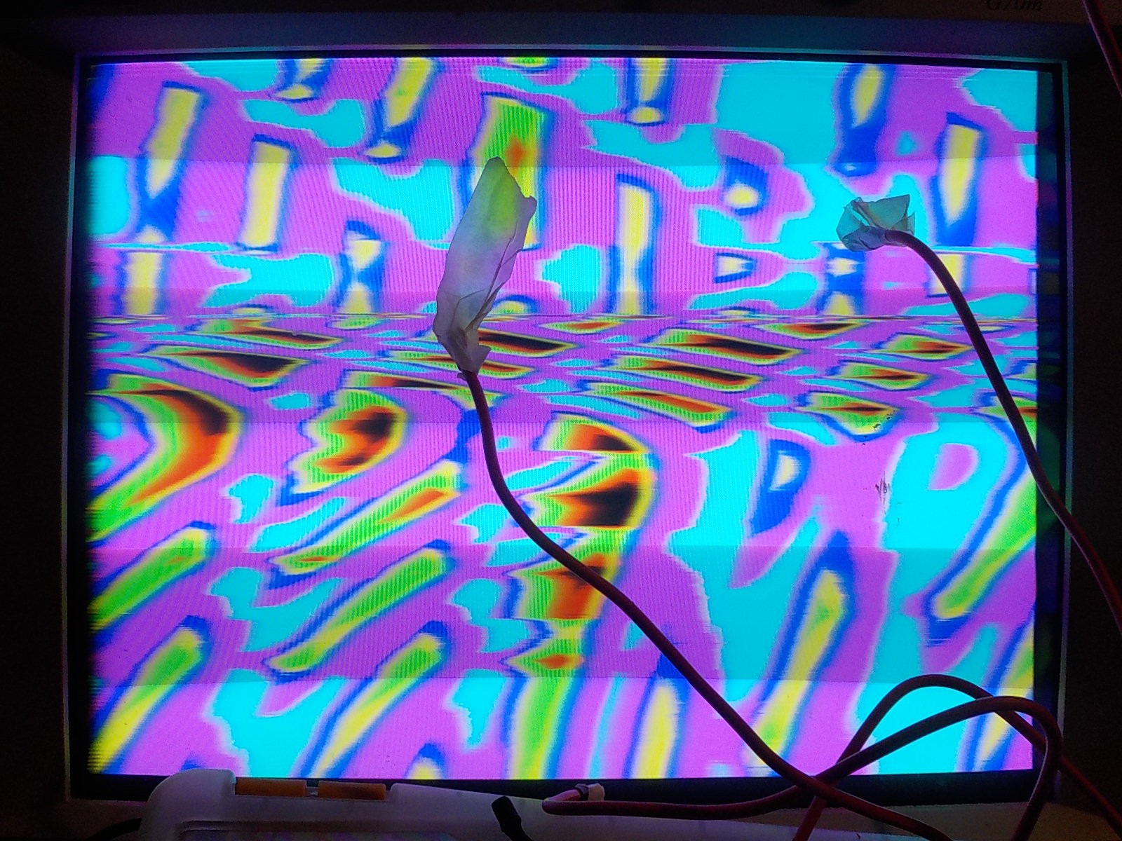
Screenshot of the blob output.
![]()
Rainbow stripe output was used when creating this video.
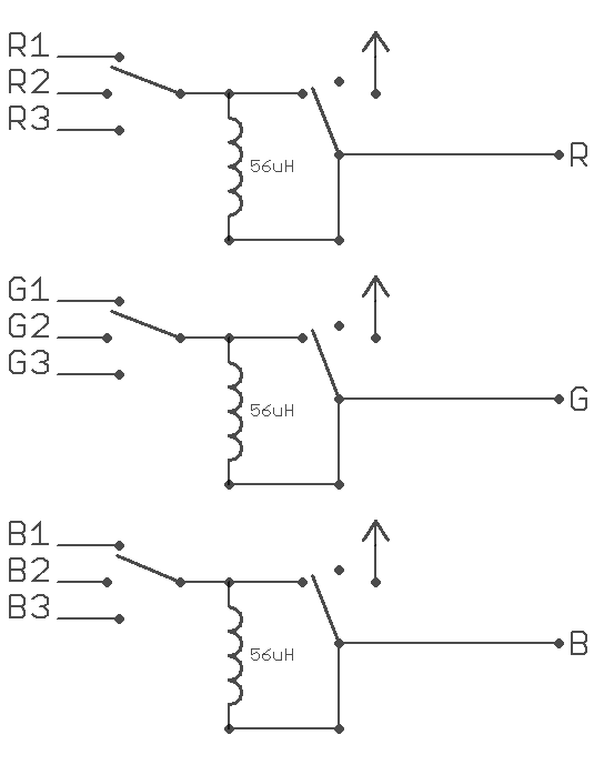
I used three sp3t switches to select between the different R,G,B outputs. This means I can have the red coming from the rainbow lines, the blue coming from the blobs, and the green coming from the rainbow lines; or any other possible combination.
I also added the option to force a colour channel to pass through a 56µH inductor or be connected only to VCC. Passing through an inductor causes a blurring effect. Blurring is applied to colour channels individually so it can produce new colours in the video output such as pink when red bleads into blue. Connecting a colour input to VCC limits the output pallet. A video that was showing all possible colours will be limited to reds, blues, and pinks if the green channel is always VCC.
![]()
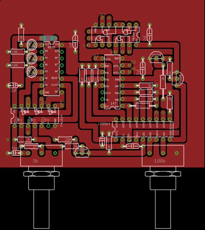
There's no PCB for this circuit because it was produced by soldering directly to panel mount components.
This video was produced with the red channel connected to the coloured line output with inductor blur, the blue channel connected to the blob output without blur, and the green channel connected to the rainbow stripe output with blur.
-
Video Circuit part2: Warped Lines
03/06/2016 at 02:54 • 0 commentsMy plan for the video circuit was to have each finger generate a unique set of curvy lines that follow its position. After that the curvy lines can be combined into a single signal and fed to a circuit that uses them to make interesting colour patterns.
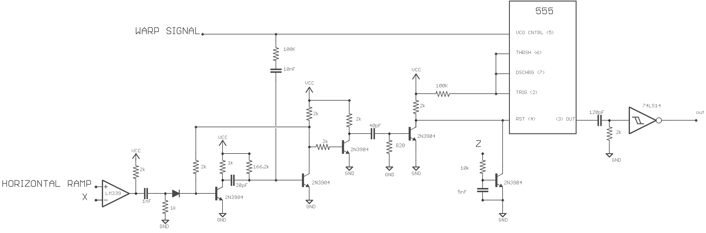
I'm taking advantage of a 555's often ignored reset and VCO circuitry. By building a 555 astable circuit and resetting it on the horizontal crosshair output I produce several vertical lines that follow the finger back and forth across the monitor. I can create curves in the line sequence by applying a signal to the 555 VCO input. If this signal responds to the vertical crosshair output I end up with a pattern of curved lines that respond to the finger's vertical movement too.
![]()
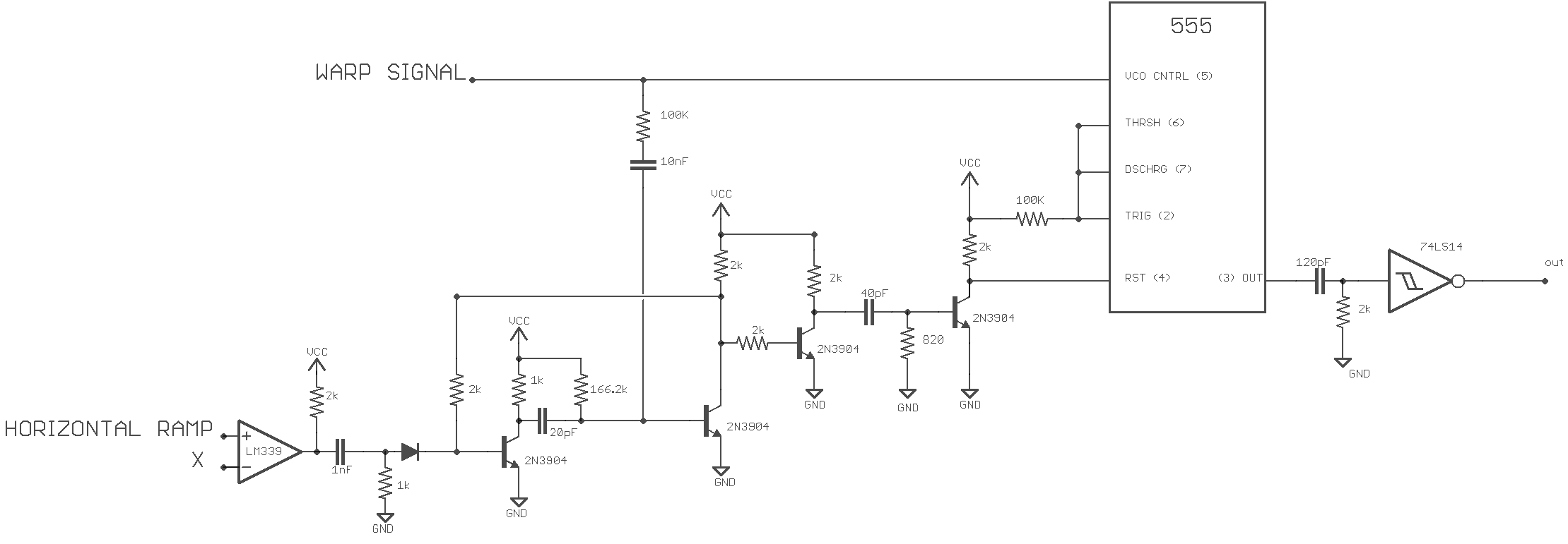
There's one of these circuits for each of the five fingers. It takes in the X position of a finger and a signal used to produce line curves (Warp). It produces a video signal of curved lines.
I cheated on the 555 astable circuit and didn't use a capacitor on pins 6,2 or a resistor on pins 6,2 and 7. This works because I'm running a bipolar 555 so fast that the width of the low pulse is how I like it without the delay caused by these components. They'll probably be needed with the much faster CMOS derivative.
The NOT Schmitt on the 555's output is used to make the lines thinner and to produce coloured lines on a white background. Without the inersion it's coloured lines on a black background.
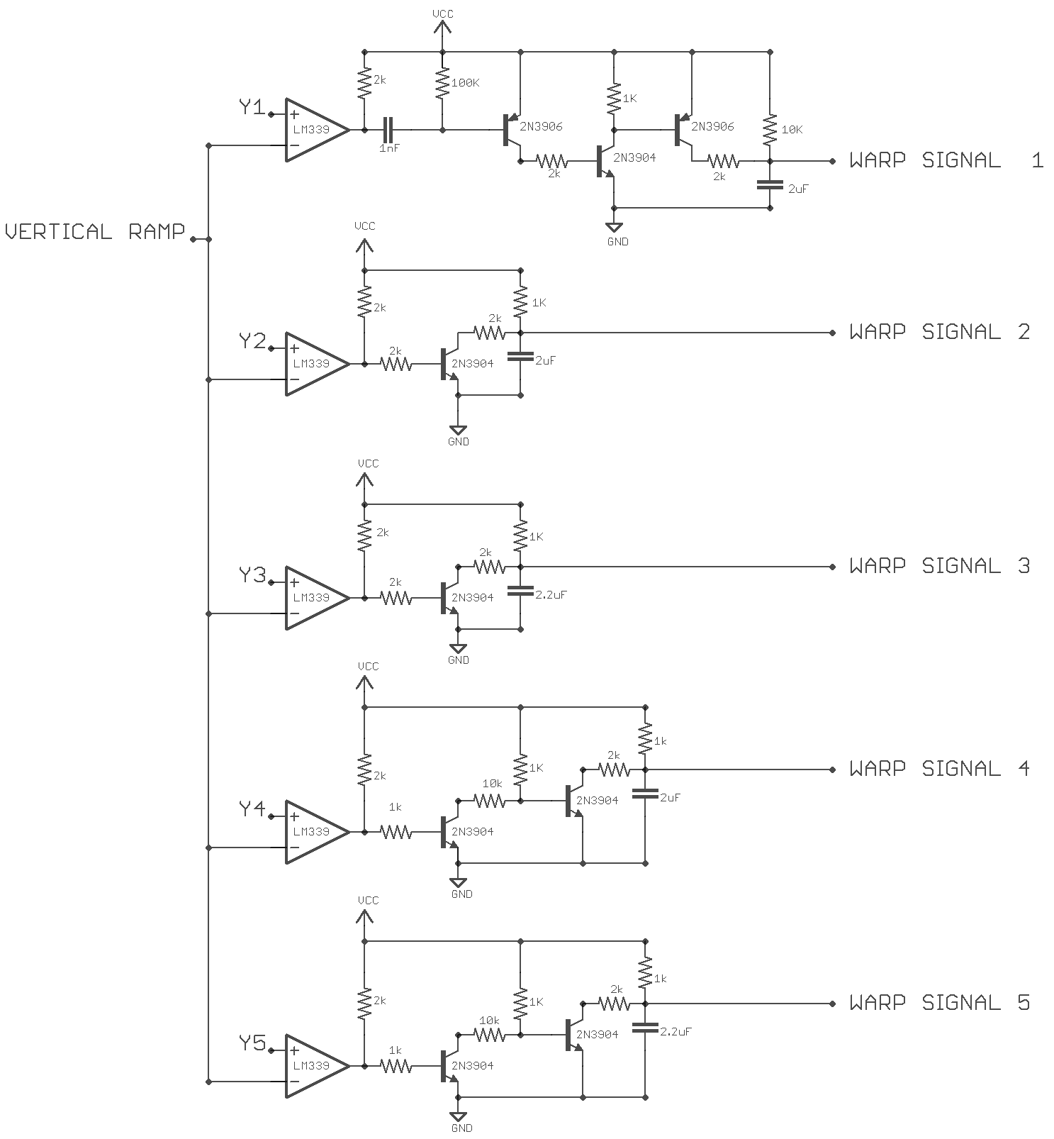
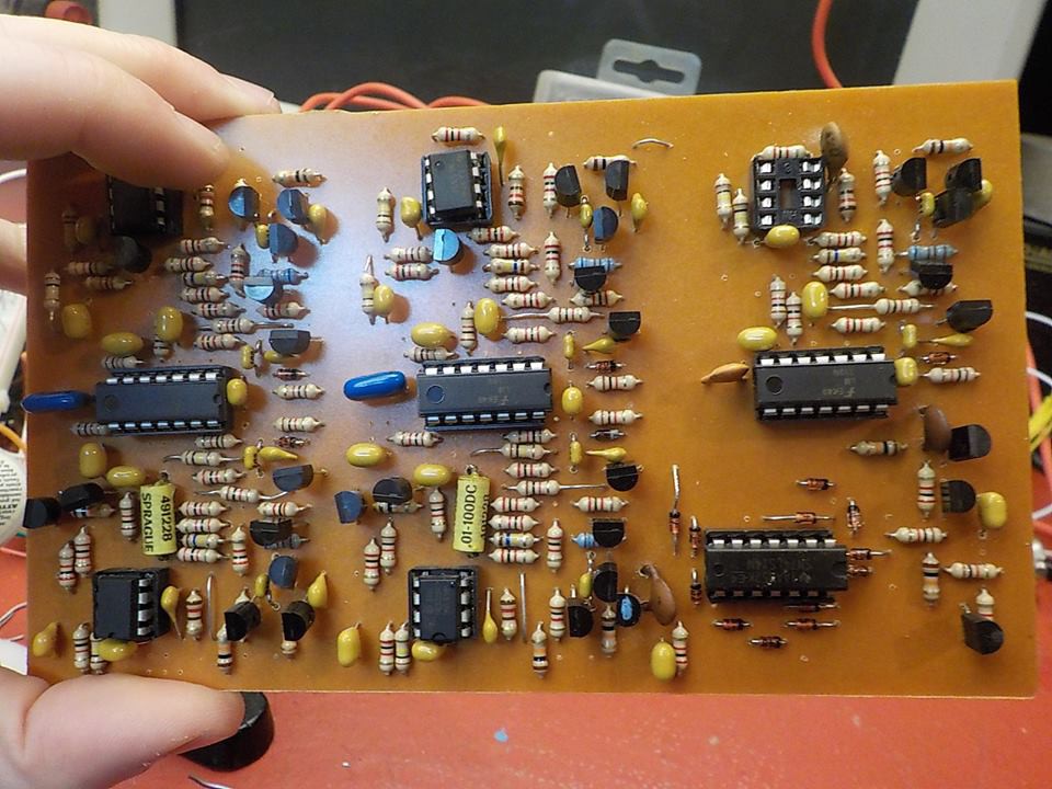
These are the five circuits used to give each finger a unique curved line pattern. Two of them are clones with slightly different component values. They're all variations on unregulated capacitor charge ramps. The 2uF capacitor at the end of the signal chain switches from charging to discharging when the comparator output goes from low to high because the vertical ramp has exceeded a Y signal.
![]()
![]()
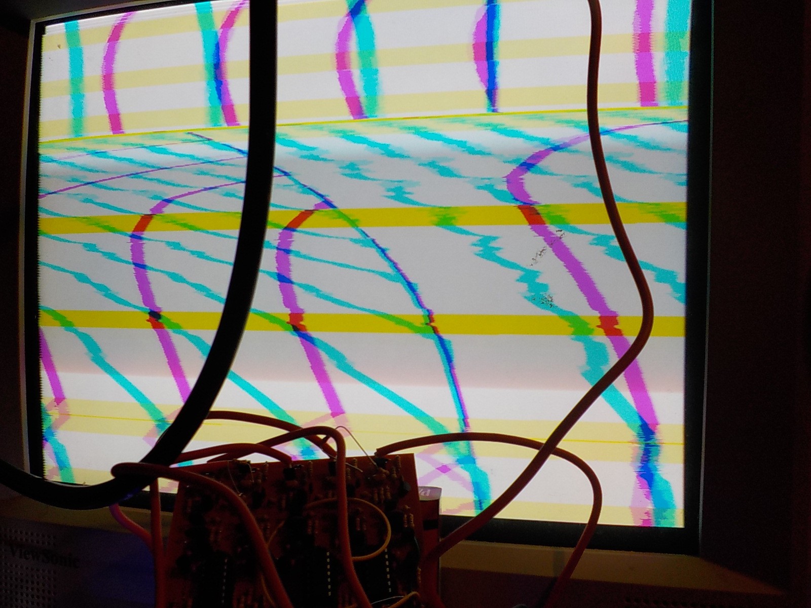
Picture showing the output of two different line generator circuits in pink and cyan. Z control was not implemented yet, so the lines are visible when no fingers are touching the screen.
Next I added an interaction with the Z axis. Increasing the voltage from the Z input increases how long the 555 is kept in reset. This makes lines disappear and curve differently.
![]()
Here's me playing with the X, Y, and Z axis of a single finger.
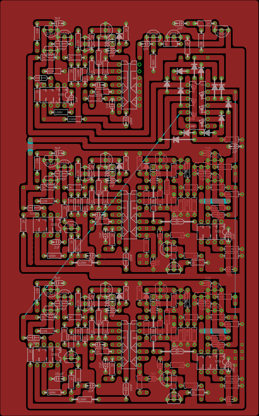
There's a few issues with the PCB. Somehow I forgot that all the ramp inputs to the comparators need to be connected together. I plan to make another version of this board combining it with the gradient board coming up next. The diodes around the Schmitt gates are part of the gradiant system.
![]()
![]()
-
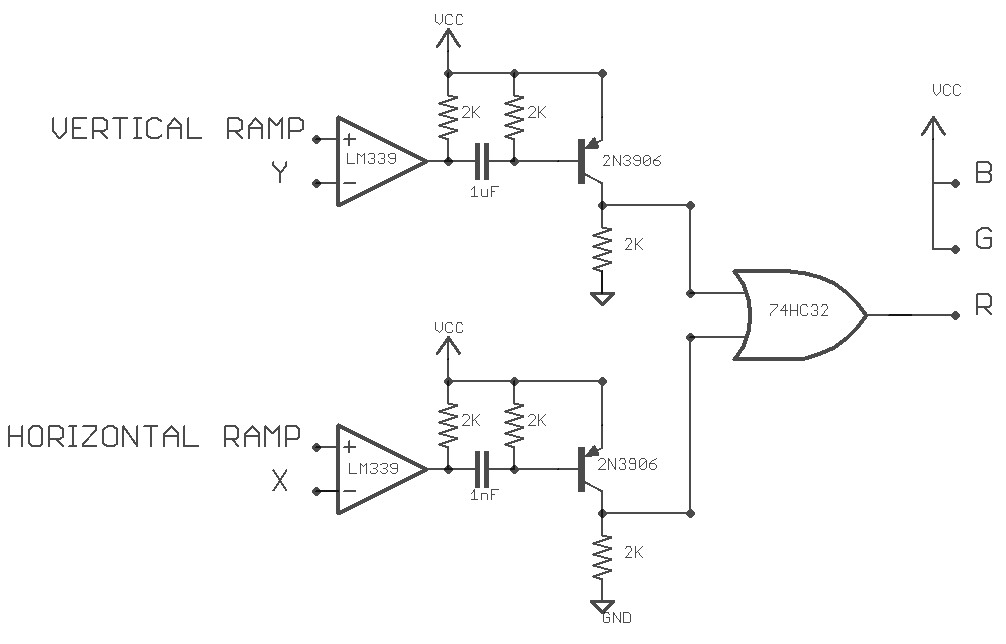
Video Circuit part1: Crosshair
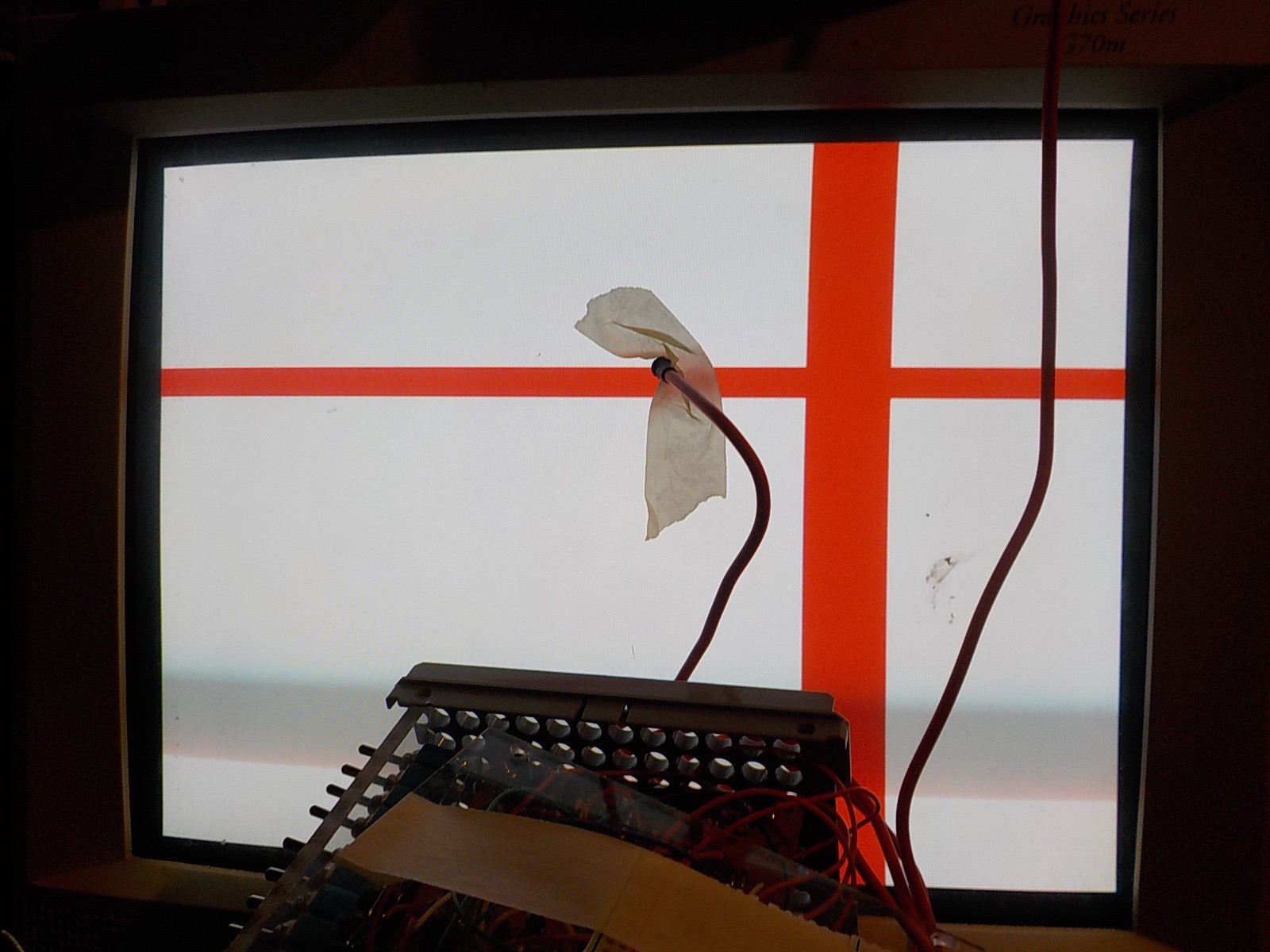
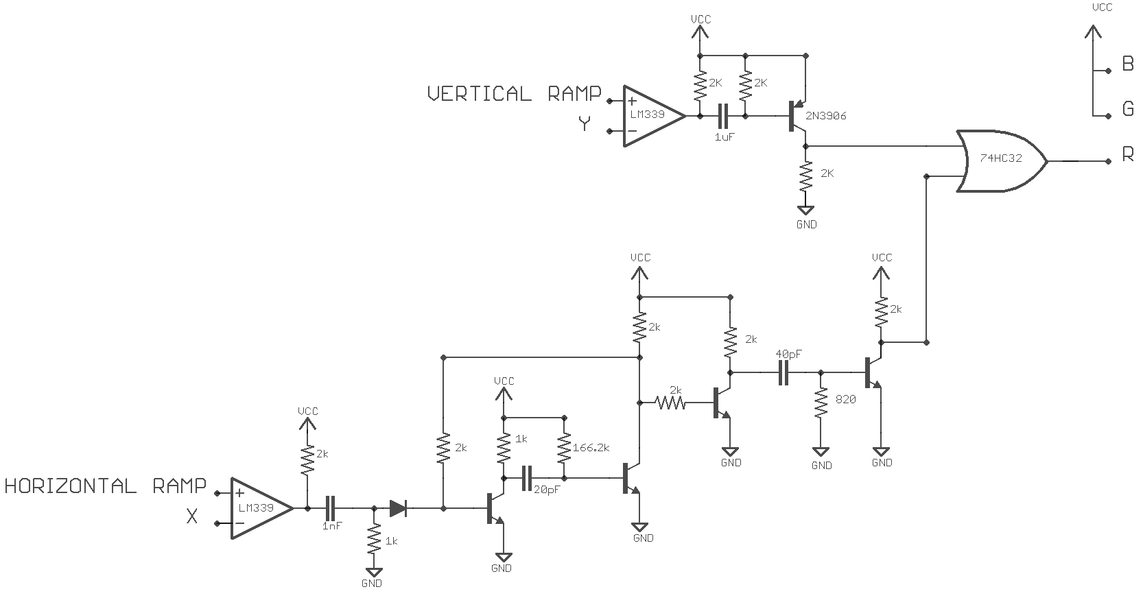
03/06/2016 at 02:41 • 0 commentsI'm starting with a simple crosshair video interaction circuit to show the X Y position of a sensor on the monitor. The circuit works using an LM339 comparator to compare the horizontal and vertical ramping voltages to the X,Y voltages. The comparator output transistion from low to high when the ramping voltages become grater than the X,Y voltages. This triggers an edge detector circuit to output high for a set amount of time. The edge detector on the vertical section outputs higher much longer because it needs to stay active for several scanlines to draw a horizontal bar. The outputs of the two edge detectors are combined with an OR gate that goes to the RGB inputs. If I'd used an AND gate I'd be producing a small rectangle where the two lines intersect.
![]()
![]()
This is the output of the circuit on the monitor. As you can see the horizontal position is off. This is because of the signal delay between the detector and sample-and-hold circuit. Adding separate ramp triggers only stops this from producing wrap-arounds at the edges of the screen, it doesn't remove the effect entirely. I had this issue with the zapper project and solved it by using a 555 to produce many vertical lines so there was no obvious center to be out of position.
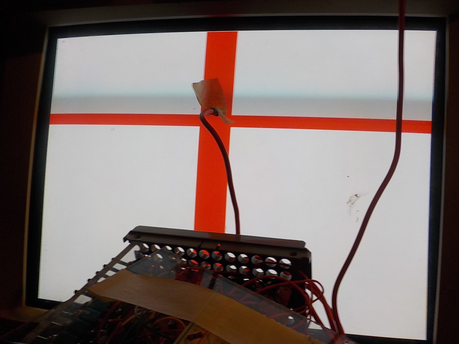
This time I'm solving it in a better way. I'm adding a monostable circuit to the horizontal axis. The monostable delay is tuned to equal the time required to draw a scanline minus the sensor signal delay. This way an output pulse is produced in the correct horizontal position on the next scanline down.
![]()
![]()
Crosshairs aligning to phototransistor.
After rethinking some things I've realized I can eliminate the signal delay problem completely by moving the monostable delay circuit into the light gun curcuit. This way the horizontal sample-and-hold circuit will store a value matching the ramp exactly when the raster beam was detected; but produced from the ramp signal one scanline after the detection.
-
Putting it all on one board
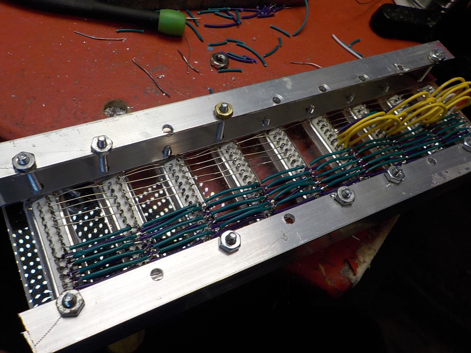
03/04/2016 at 06:14 • 0 commentsThe design shows in the last step wasn't very good. There were too many wires running between the stack of boards on my hand and from the stack to the audio/video effect bus on my forearm. I was spending so much time dealing with the mess of wires I could never get to designing the audio/video effects. The solution was to abandon that iteration of the project and design a new one. I put the VGA generator, sample-and-hold, and light detector circuits onto a single PCB and dropped the idea of swappable effect modules. The LED display board is no longer part of the project.
![]()
![]()
-
Putting it all together
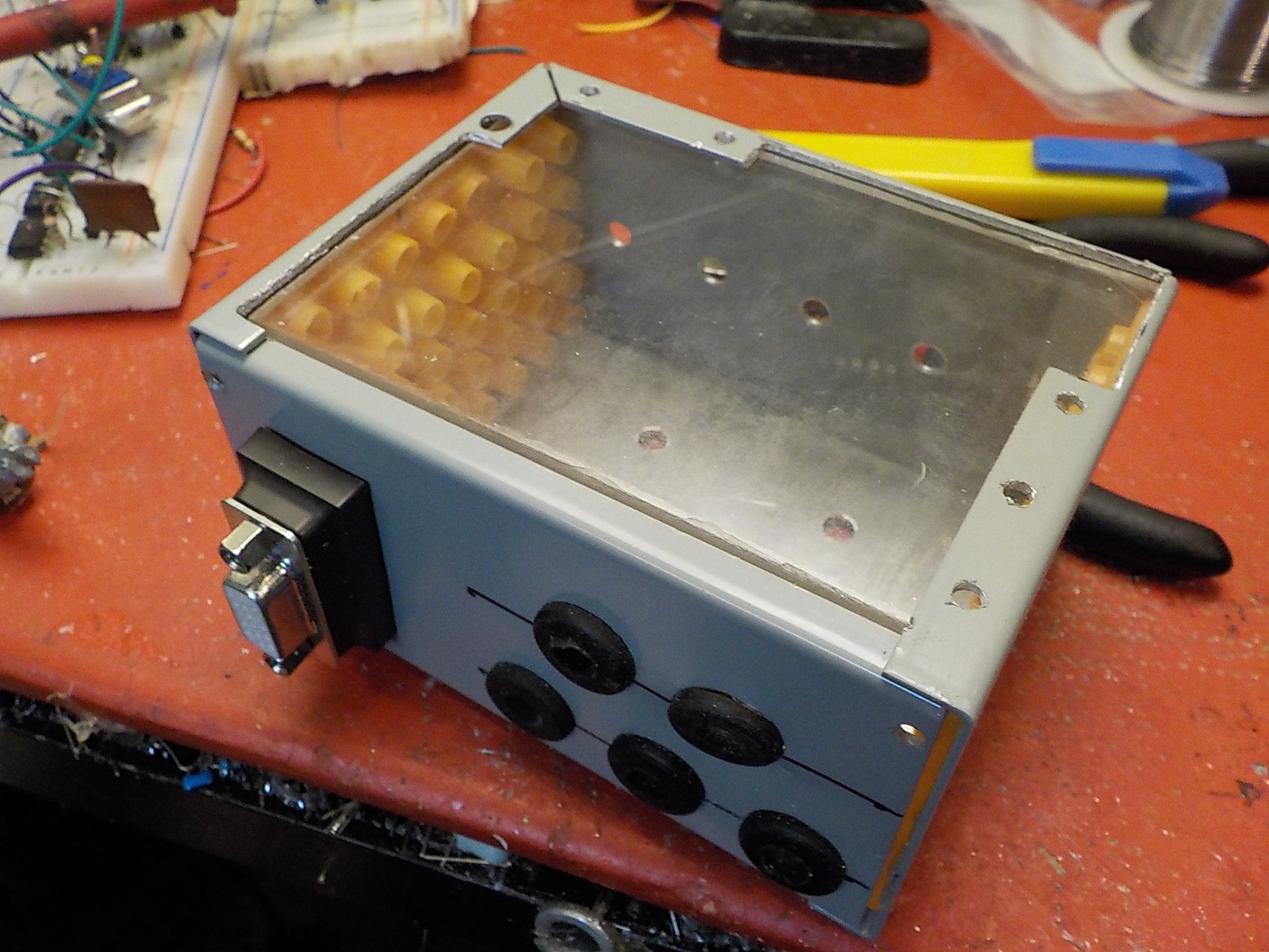
03/04/2016 at 06:08 • 0 commentsI put the stack of four boards into a metal box measuring: 2" tall, 4" wide, 3" long. I cut the top off the box and replaced it with an acylic panel so the LEDs would be visible. The plan was to put this box on the back of my hand and run wires to audio and video effect circuits located on my forearm.
![]()
The back of the box showing the VGA connector and holes for running wires to the effect boards.
![]()
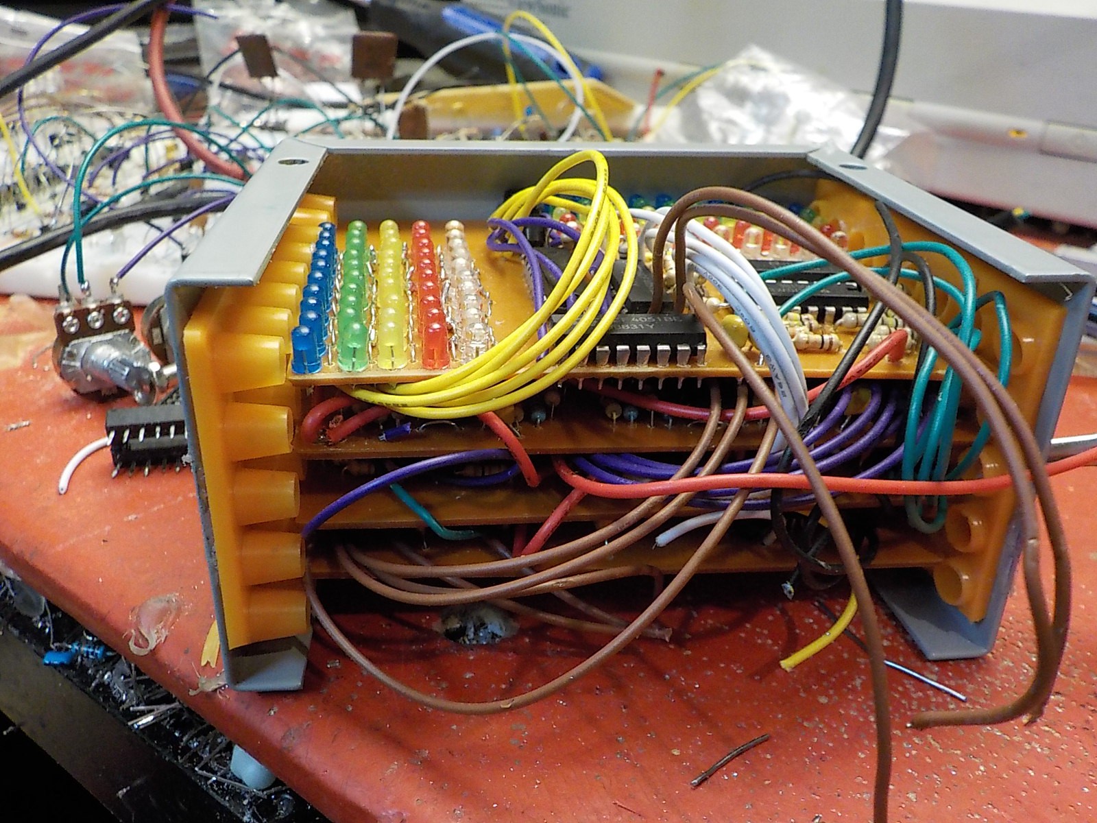
The stack of circuit boards. Top to bottom: LED Display, Light Detectors, Sample-and-holds, VGA signal generator.
![]()
I wanted to build audio/video modules that could be swapped out like the cartridges in an old game console. I used DB25 connectors for this. Signal wires connect to each DB25 in a parallel bus.
![]()
The main control system connected to the audio/video module bus. As you can see the wires running from the hand to forearm are getting pretty hairy. The wires needed were:
Description # of wires X, Y signals 10 Horizontal and Vertical ramps (needed for video effects) 2 Hsync, Vsync (needed for video effects) 2 VGA RGB (video effect out) 3 Z-audio-mixer (audio effect out) 5 VCC,GND 2 Total 24 I wasn't running the Z position signal to the audio/video effect boards because at this point I wasn't planning on using those for anything other than mixing the volume levels and adding those would go over the DB25 pin count.
-
LED position display
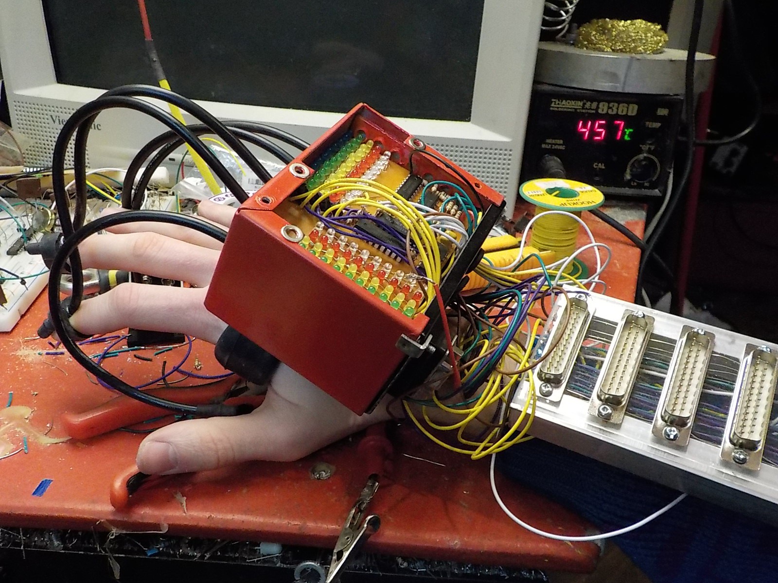
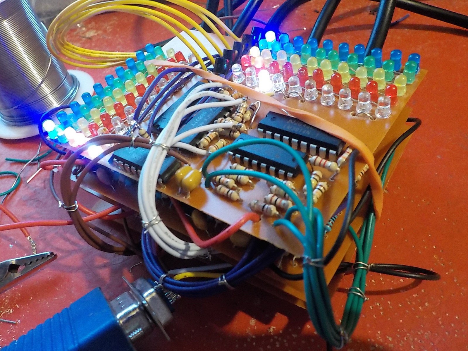
03/04/2016 at 05:21 • 0 commentsI couldn't resist the urge to put cool lights on this project. For each finger I wanted a row of LEDs to indicate the X position and another for the Y position. The Z value is indicated by the brightness of the LEDs lit up in the X and Y coloumns.
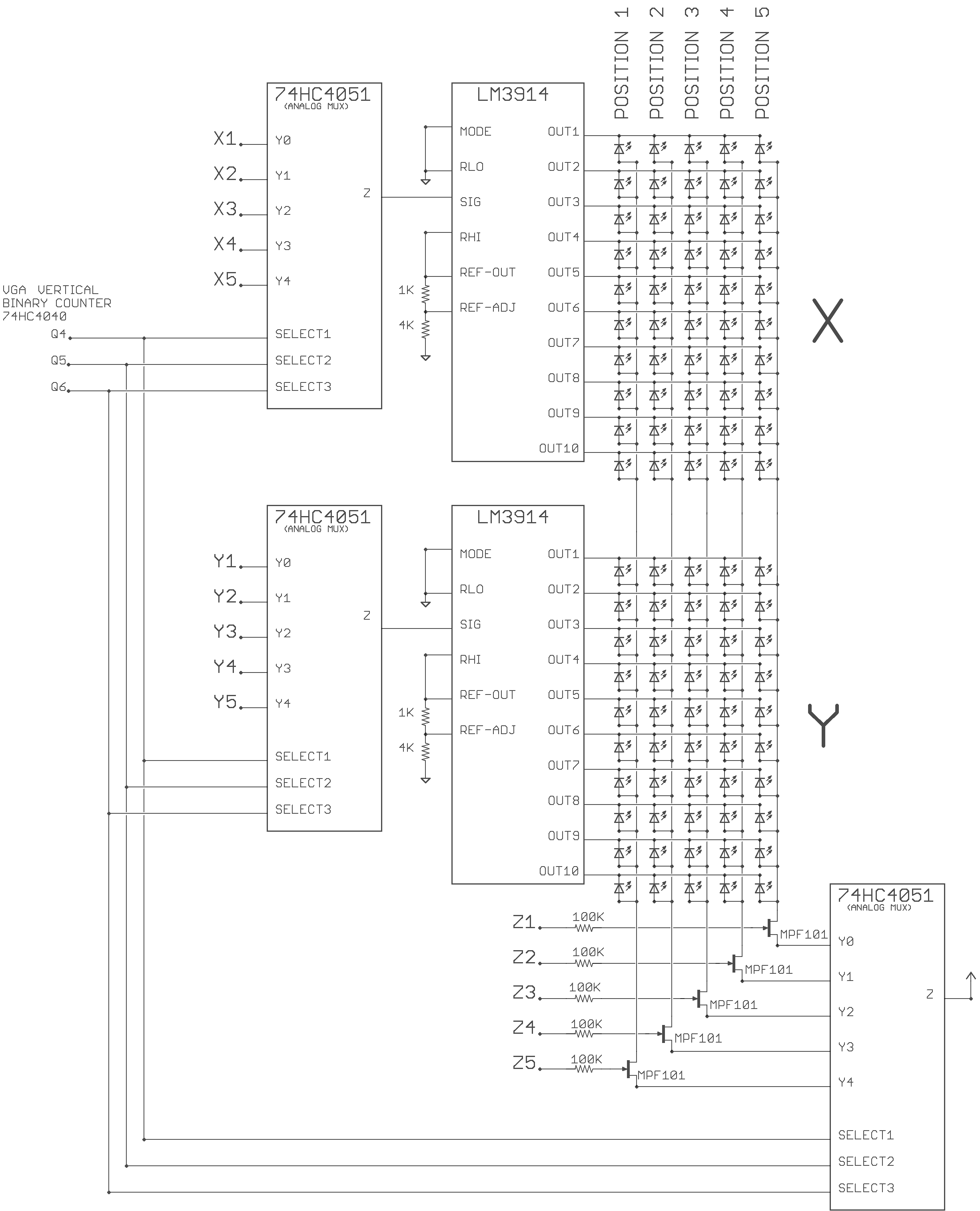
The LM3914 is a ten LED dot display chip. It indicates an analog voltage level by illuminating one of the ten LEDs connected to it. I didn't want to use ten LM3914s to display the ten values, so I came up with a 5x20 LED multiplexing matrix design using 74HC4051s (analog multiplexers).
Only one of the five LED columns is illuminated at a time but they're cycled through fast enough to look like they're all on at once to human eyes. The signal to decide which column is illuminated come from three of the binary outputs on the vertical binary counter on the VGA board.
The top ten rows show a dot to indicate X position, and the bottom ten rows show a dot to indicate X position. Analog Multiplexers select different X,Y values to send to the LED dot chips depending on the column being illuminated.
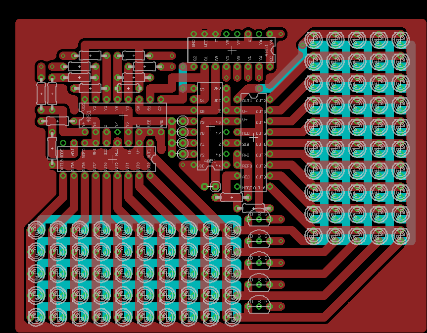
![]()
![]()
![]()
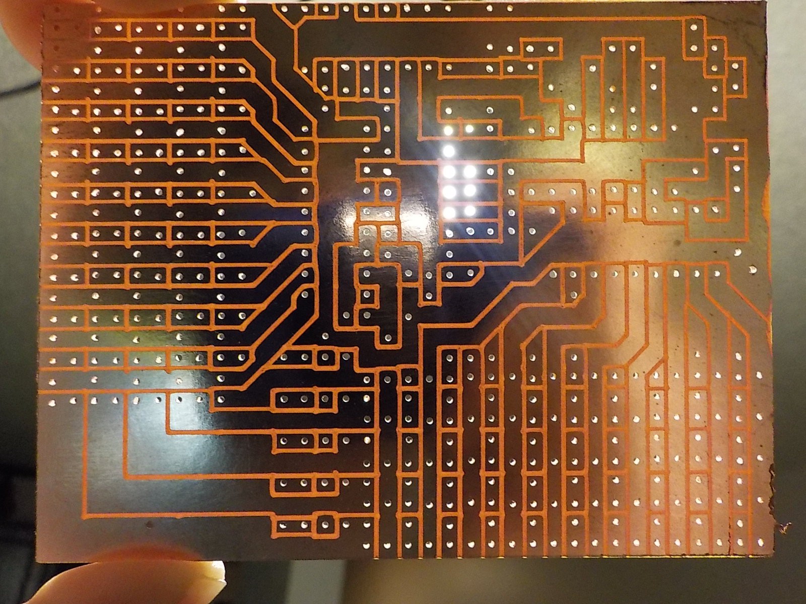
I wasn't very happy with how this PCB turned out. I wanted it to be the same dimensions as the previous three boards, but there was too much stuff to fit cleanly. I had to use diagonal traces and too many jumper wires.
![]() The display board stacked on top of the VGA signal generator, light detectors, and sample-and-hold boards.
The display board stacked on top of the VGA signal generator, light detectors, and sample-and-hold boards. -
Z-axis / Audio Mixer
03/02/2016 at 07:08 • 0 commentsThis project will have five separate audio tone generators controlled by the X,Y voltages. I wanted the volume of these tones to be controlled by the distance of the fingers from the screen (Z). I'm not very musically inclined, but I can tap a pattern with my fingers. Using the distance of the fingers as volume should translates the tapping motions to a sequence of notes.
It wasn't possible to get a true Z-axis value like it was with X and Y. Those aren't effected by anything other than the physical phototransistor position provided there's enough light to trigger the detector circuit. The Z-axis is based on the amount of light hitting the phototransistor, so it's effected by both the distance of the phototransistor from the monitor and the brightness of the monitor.
![]()
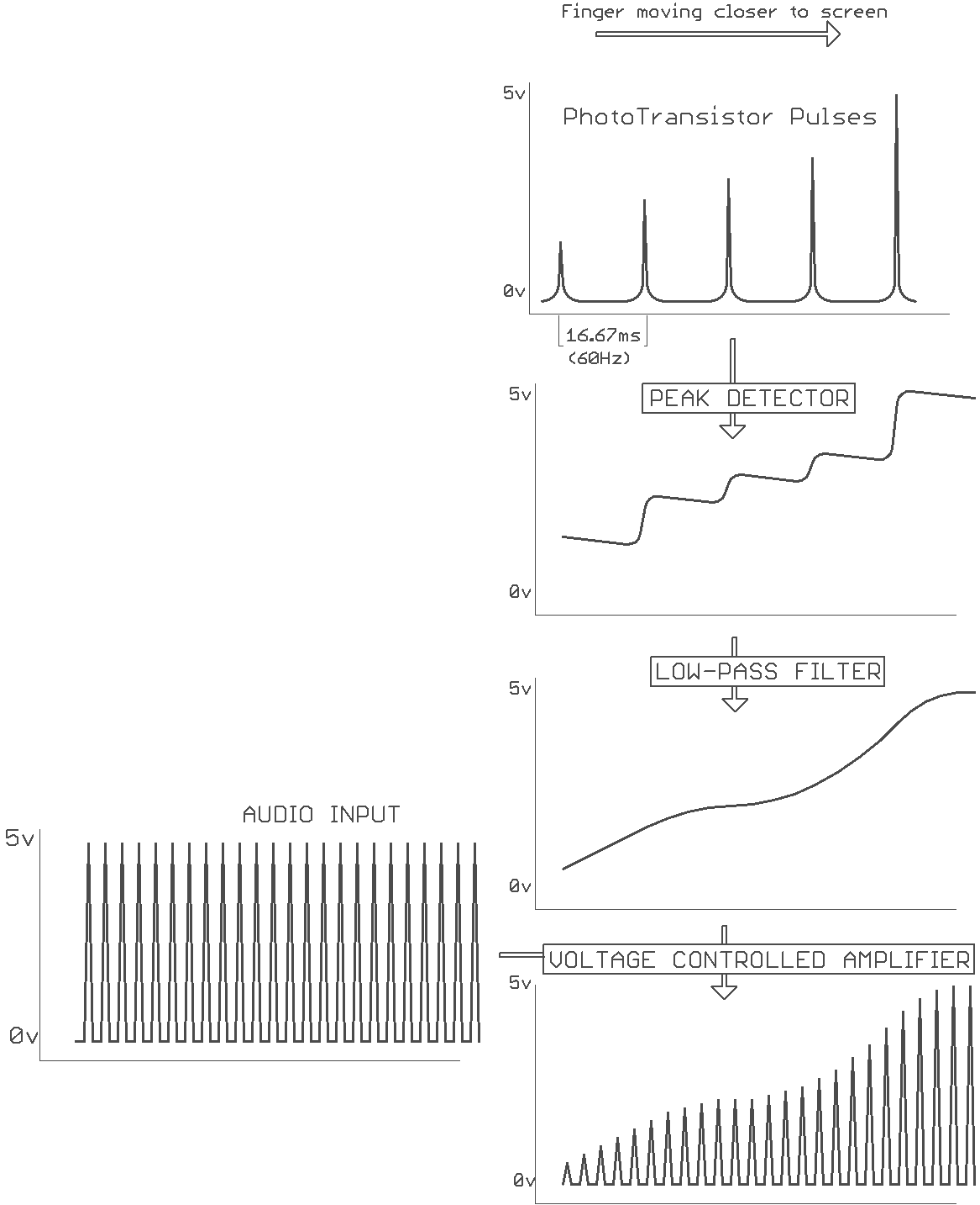
When the raster beam hits the phototransistor it produces a short pulse that increases in voltage based on the brightness and distance of the sensor. The phototransistor pulse is fed into a peak detector to get a consistent voltage based on the pulse height. The pulse occurs at a frequency of 60Hz (monitor refresh rate) and this shows up in the peak detector output. It's filtered out with a low pulse filter so there isn't a 60Hz hum in every audio signal that passes through the voltage controlled amplifier.
![]()
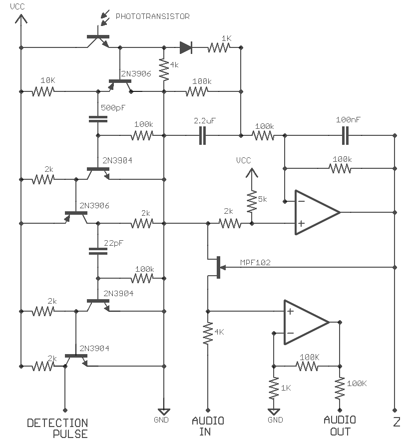
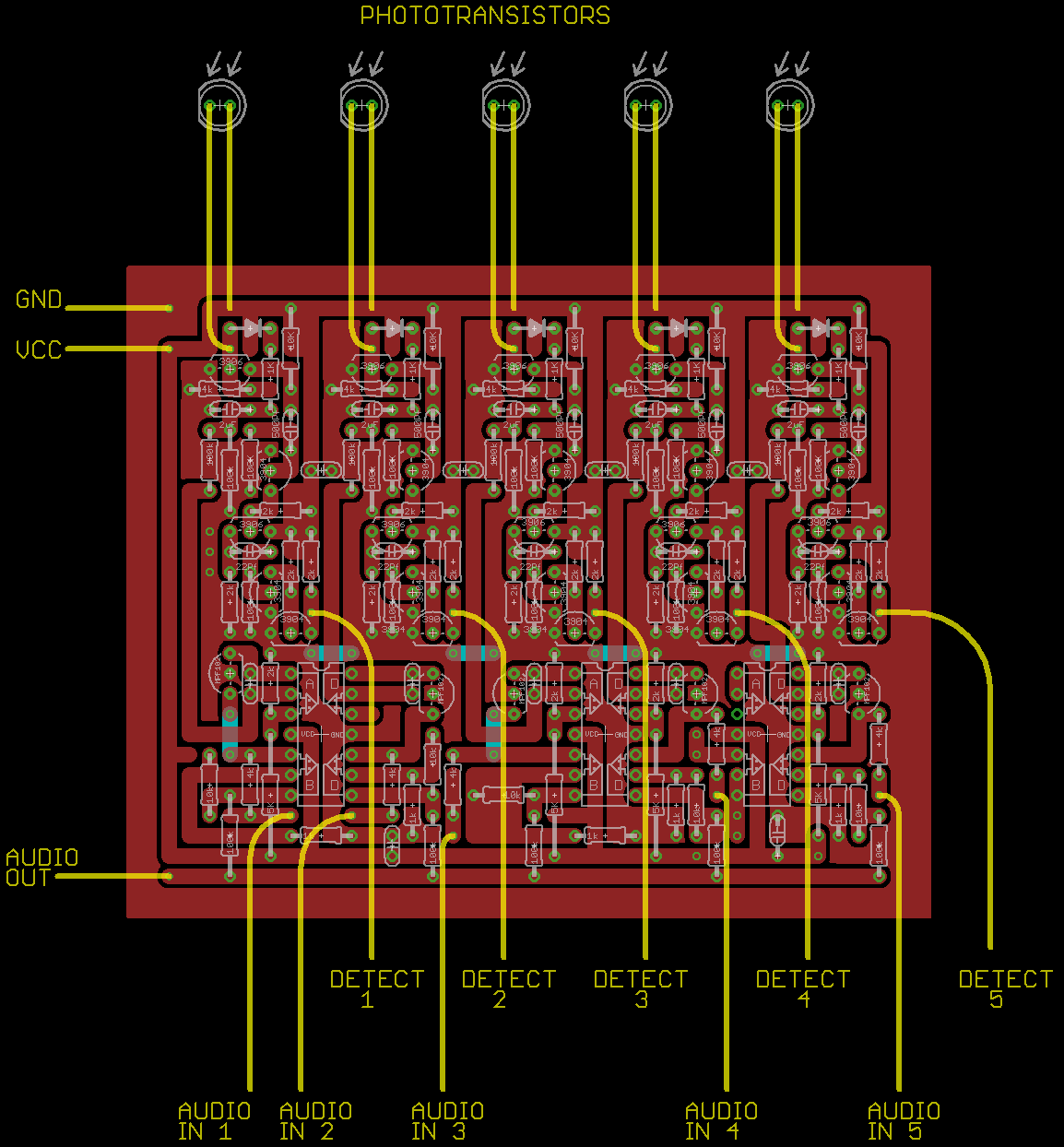
Schematic showing the Z-axis output, audio mix, and detection pulse circuit. There are five of these (one per finger). All five audio outputs connect directly together to form a single mixed channel.
Using the Z-axis to manipulate video was an afterthought so the Z output to the video synth is not properly buffered or filtered. That had to be placed on the video synth board. Making some changes to fix that is on my todo list.
![]()
![]()
![]()
Here's me playing with the X,Y, and Z axis. The video effect circuit used to generate this comes in the next step.
-
Light Gun Circuits.
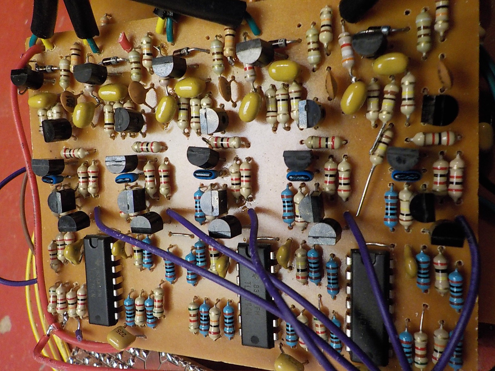
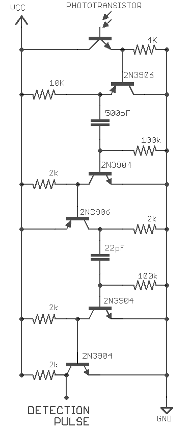
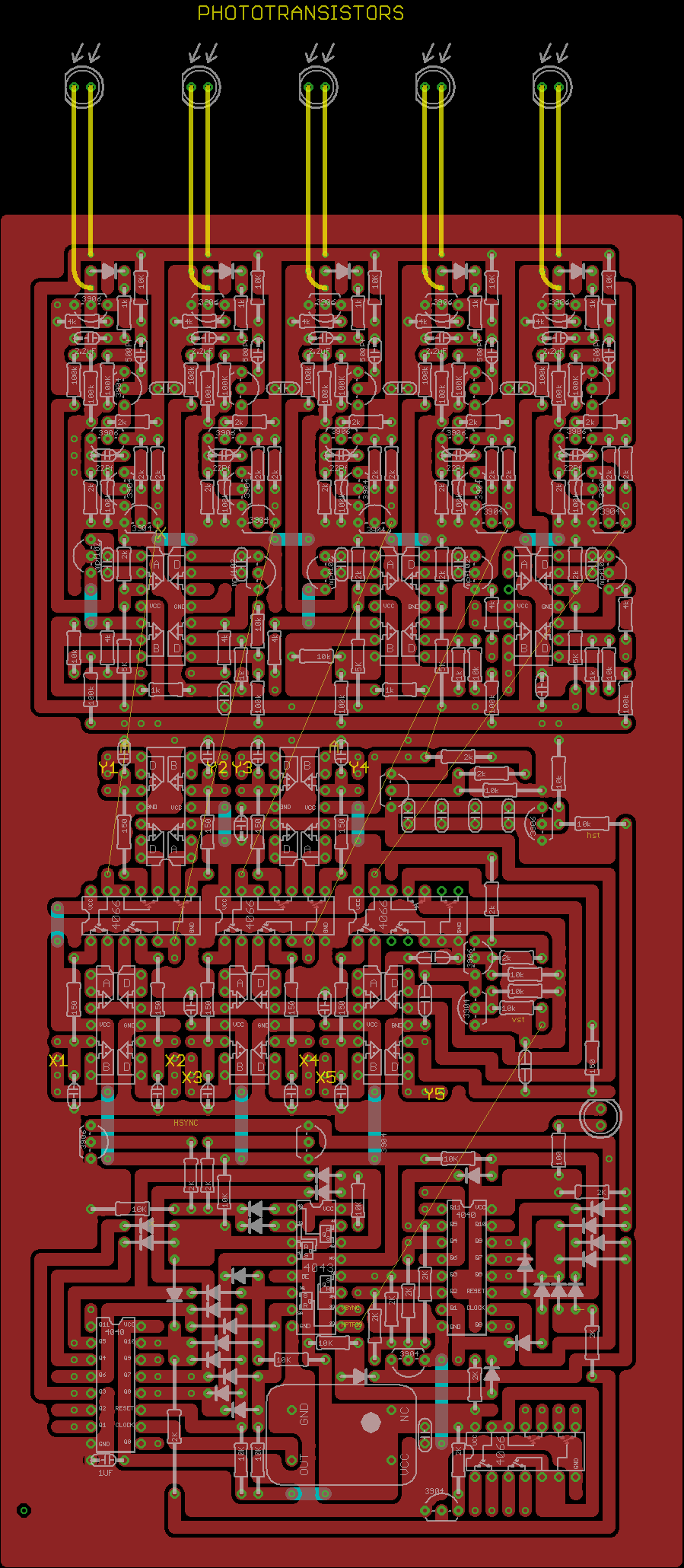
03/02/2016 at 07:02 • 0 commentsThe glove uses light-gun sensors on each finger. I designed my own circuit because I couldn't round up five NES zappers. Cloning the zapper wasn't an option because the IR3T07A chip it uses has been out of production for decades.
The circuit uses two stages of edge detectors and amplifiers: Detecting the edge of an edge to produce an output pulse about 0.6 μs long.
I'm not 100% satisfied with this circuit. It uses five transistors. I feel like I should be able to reduce it to four.
![]()
![]()
The phototransistors are wrapped in heat-shrink tubing. This isn't just to protect the wires. The detector circuits will not work without it. They need a sharp pulse when the raster beam is pointed directly at the phototransistor. The pulse rises more gradually without the tubing because the phototransistor picks up the raster beam from the side as it approaches.
-
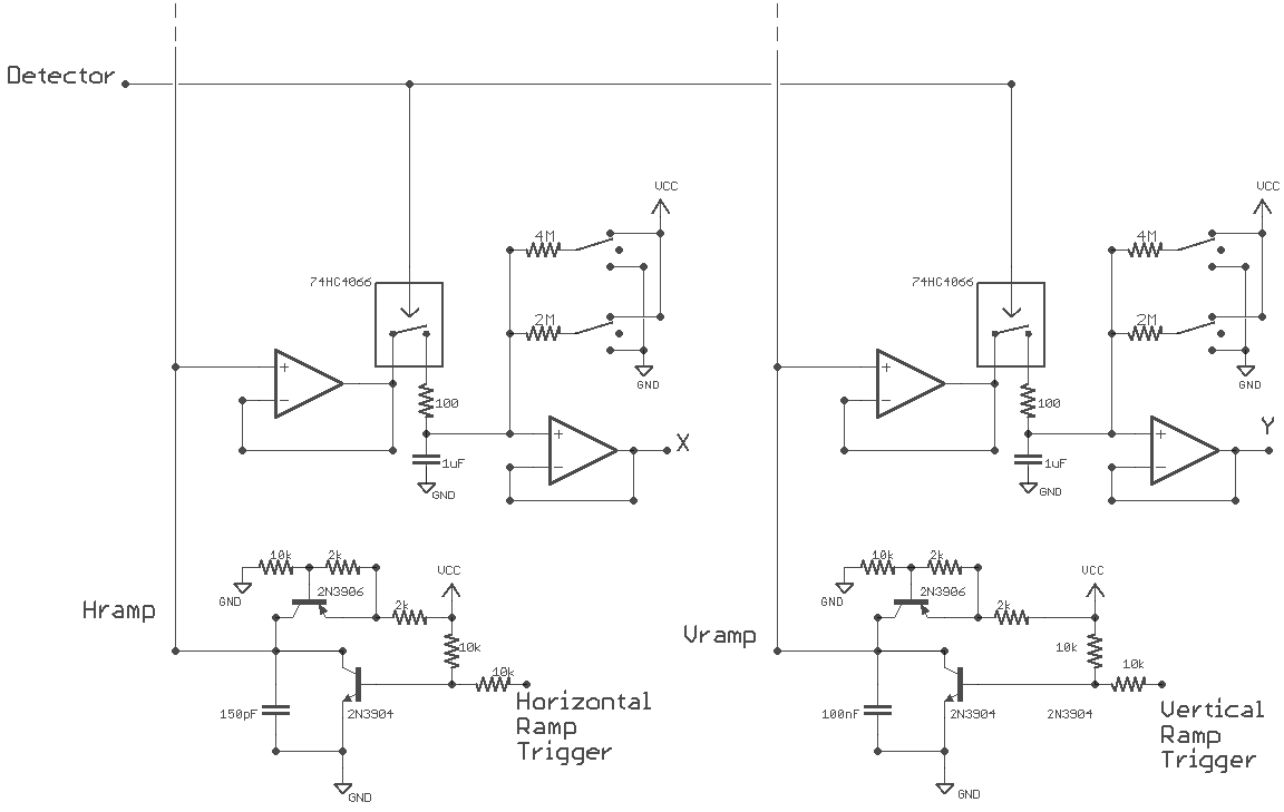
Ramp Circuit / Sample-and-Hold
03/02/2016 at 06:22 • 0 commentsThis is very similar to the circuit design used in the NES Zapper project except now there's five separate X,Y sample-and-hold pairs sharing a common pair of horizontal and vertical ramps. I've improved the design by adding a resistor in series with each holding capacitor. This prevents the voltage it holds from changing values too quickly which keeps the X,Y outputs from being jittery. This makes video effects driven by the X,Y outputs look a lot better.
The ramp generators have one less transistor in them now. Last time I was using Hsync and Vsync as ramp triggers and those are normally high pulse low. The new VGA board outputs a separate set of ramp trigger pulses that are normally low and pulse high so there's no need for a transistor NOT gate between them and the ramp circuits.
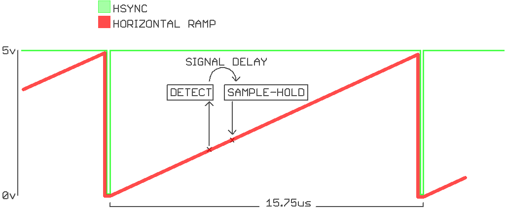
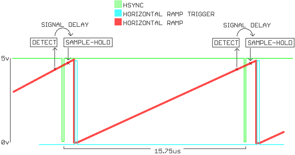
One less transistors is a nice bonus, but the primary reason for not triggering the horizontal ramp with the Hsync pulse is related to signal delay in the light gun. There is a delay lasting about 3 µs between the phototransistor picking up the raster beam and the sample-and-hold circuit recording the ramping voltage. This isn't much of an issue most of the time, the holding voltage just ends up slightly higher than the ramp voltage at the time of raster detection.
![]()
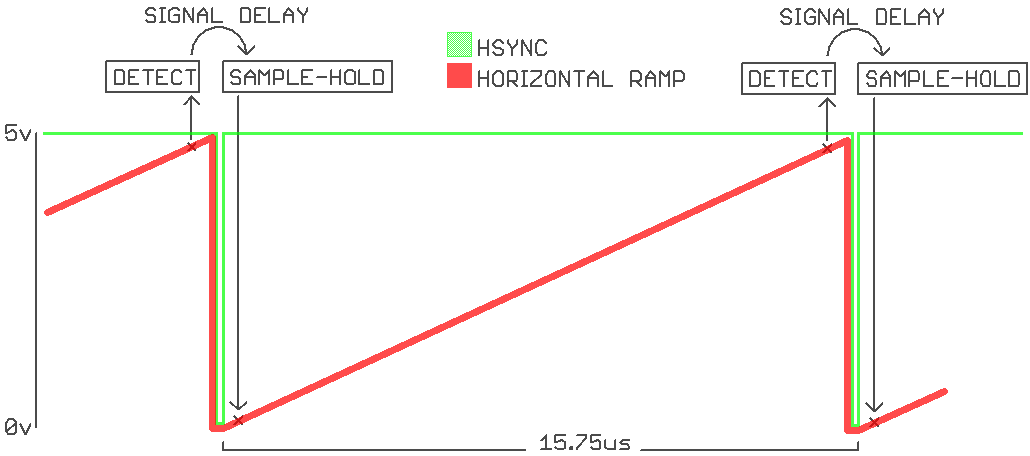
The problem becomes much more serious when the phototransistor is near the right edge of the screen. The ramp circuit is triggered (resets to 0v) between the light detection and the sample-and-hold. This produces a holding voltage that indicates the phototransistor is all the way on the left side of the screen.
![]()
The solution was to trigger the ramp circuit slightly after the Hsync pulse. This way when the phototransistor is at the far right of the screen the ramp still hasn't reset by the time the sample-and-hold takes place. I haven't just moved the problem to a different position of the monitor. The detection delay can't overlap the ramp reset because the raster beam goes off (porching) during the period where phototransistor detection would need to take place to cause the problem.
![]()
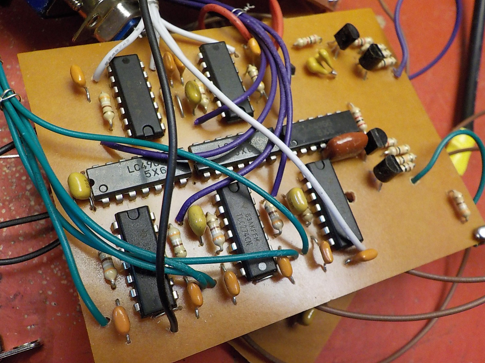
All op-amps are TLC274. Do not use audio op-amps.
![]()
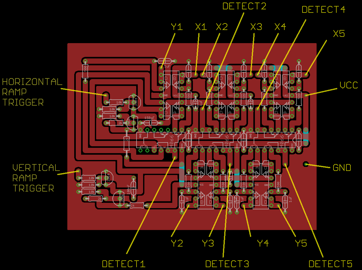
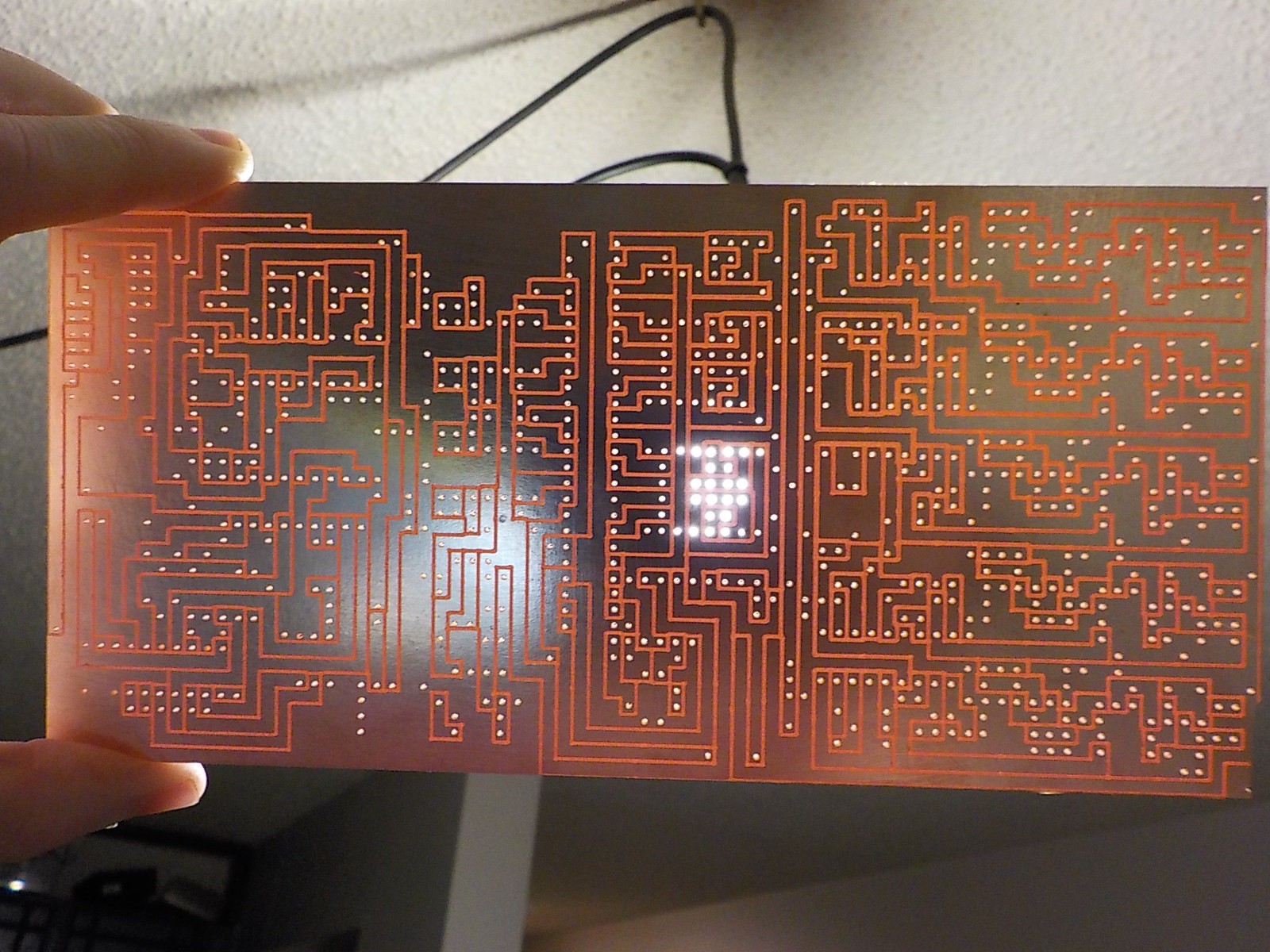
The PCB is designed to have the same dimensions as the VGA signal generator board.
![]()
I really need to replace the bit on my CNC machine.![]()
![]()
Rasterphonic Glove
Analog video synthesizer you can touch with a five finger light gun. Makes music too.
 The display board stacked on top of the VGA signal generator, light detectors, and sample-and-hold boards.