 newdrive
On the 4-8th may 2016, we finally attended the French national robotics cup, organized by "Planète Sciences" a non-profit organization. We will speak here about the wheelbase redesign, the new electronics, and the new algorithms (more on that later).
We attended a few days before the German robotics cup, but we were not able to play on the field due to a general motor controllers failure (yes, both of them), we think it was due to the way we cabled the emergency stop. Since there were too many design flaws to overcome to use the brushless motors like in UK, we decided to redesign the whole propulsion system based on stepper motors.
That meant building new motor blocks, designing a new motherboard PCB and new algorithms in 3 days.
Thanks to our modular design, the whole wheelbase hadn't to be redesigned.The former motor block was much larger and designed to support a gear reduction system.

The former motor block assembled
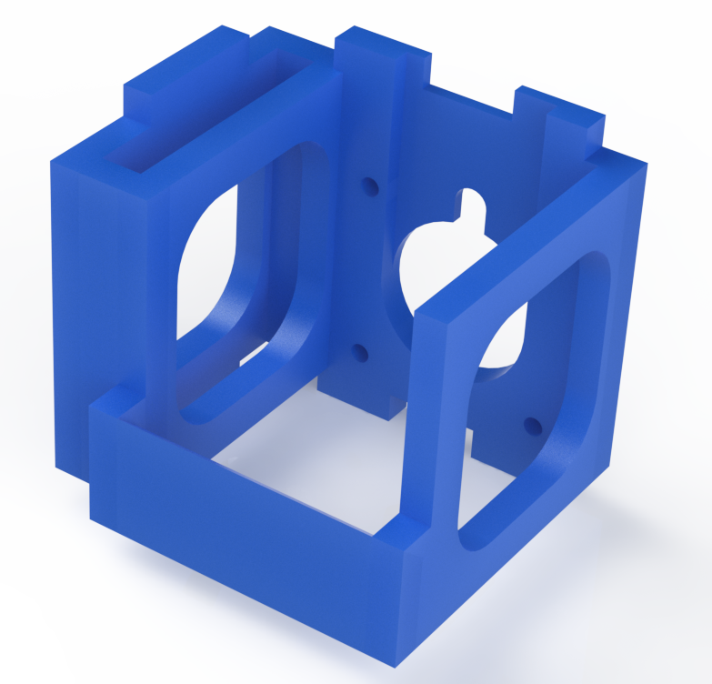
We made several iterations before getting to the right solution for the new blocks. We got through many problems with our 3D printer so we had to take it to the tournament for some one-site printing.
However that forced us to to the lightest and smallest possible design and led us to a very compact motor block :
The stepper motor we used was a standard NEMA-17-style one like this (5mm shaft) :

The integration was quite easy, and we were just on time to be homologated
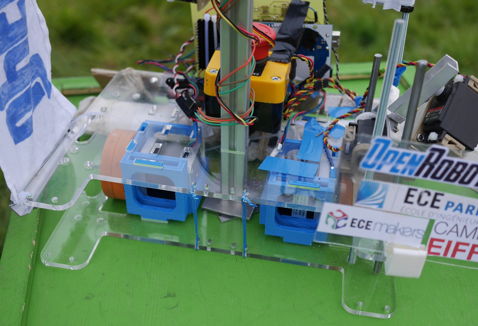
The wheelbase fully integrated
We drove the motors with a DRV8825 High Current Pololu stepper driver, powered by two LiPo batteries in series for 24V operating voltage, since it is less likely to skip steps with higher voltages in the engine coils (the magnetic field establishes itself more quickly). We used a THN 30-2412 Tracopower DC/DC converter on our board for logic and servo power supply.
As you an see, we needed a quite large heat sink to dissipate the wasted energy from the 40W total propulsion system
Here is a front-side view of the board :
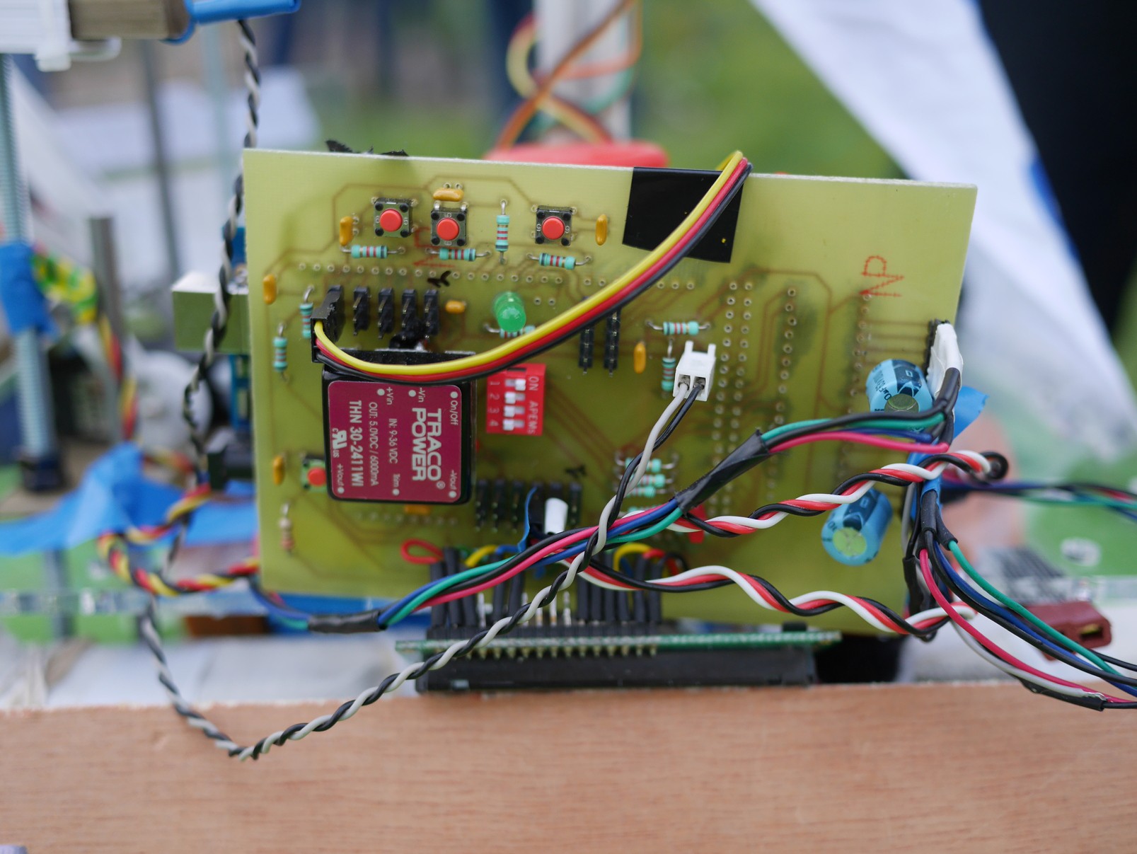
This PCB was designed as a shield for the Arduino Mega and has the several features
- 5 standard PWM servo ports
- 6 analog sensor ports for infrared and proximity
- Quad input DIP switch
- 3 Anti-bounce filtered push buttons
- 1 filtered reset button
- 1 Green LED
- 1 Red LED
- 1 starting switch port
- A TRACOPOWER 5V 6A single output DC/DC converter (9-36V)
- 2 Decoupled battery inputs
- A 16x2 LCD Alphanumeric panel (great for debug)
- 2 AMT10-V series encoder inputs (decoupled with standard 100nF capacitor like all active components)
- 2 Pololu stepper driver ports (thus easy to replace) with heat sink supporting the high current version
We used basic algorithms to drive the robot on the playing field, the whole strategy will be published in a few days with videos of the robot working at the Eurobot cup.
We will try to publish our designs as soon as possible on GitHub.
Thanks for reading ;)
Discussions
Become a Hackaday.io Member
Create an account to leave a comment. Already have an account? Log In.