Programming abstraction for Linux absolute hardware addresses
The main abstraction from the programming view is to map virtual
addresses used by Linux during program execution to physical addresses
of memory mapped peripherials. I assume that we are running with root privileges. Opening the device /dev/mem and then using mmap gives access to physical addresses in a limited range determined by the mmap parameters. The code example
attempts to blink the HPS LED and read the switch directly attached to
port GPIO1bits 24 and 25 respectively. All device addresses are from the
HPS Technical Reference Manual. The switch read works, but the LED does not blink. The code was downloaded using copy/paste to the vi editor, then compiled from the console command line with a simple gcc test_led.c -o test_led.
Speed test the HPS-to-FPGA bus
If the MSEL switches are set correctly (5'b01010) then the default boot process loads the DE1_SoC_Computer.rbf config file (in /home/root) to the FPGA. Running the increment_led program (part of the UP Linux image in /home/root/increment_leds) controls the red LEDs attached to the FPGA side. A slightly modified version of the demo code increments the FPGA red LEDs as fast as possible. Using the DE1_SoC_Computer.rbf
included with the UP Linux image, the max toggle speed 830 KHz, so one
add and loop takes 600 nSec, which seems slow. Replacing the register
increment with a C variable increment, which is then loaded into the
register, doubles the toggle speed to 1.61 MHz, for a loop time of 300
nSec. This implies that the bus transactions are dominating execution
speed. Avalon bus speed in this case is 50 MHz, or 20 nSec. The
transaction must take about 15 bus cycles to transfer a word from the
AXI-to-Avalon bus and Avalon-to-parallel i/o port. (But see below for
higher speed connect).
First steps in controlling the FPGA.
This example uses serial control on the ARM to set hex digits and led
count rate on the FPGA. Two 32-bit parallel ports were added (using
QSYS) to the my_first_ hps_fpga example on the
DE1-SoC_v.5.0.1_HWrevF_SystemCD. The parallel otuput ports were wired to
a small amount of verilog to blink the red LEDs and to drive the first 4
7-seg digits. The QSYS layout made it easy to add a port, and the
exported i/o signal bus is named in the verilog header generated by
QSYS. If the parallel port is named pio_test, then the exported signal name is pio_test_external_connection, and the signal which appears in the *.v file is pio_test_external_connection_export. The signal is added to the top-level soc-system module instance.
soc_system u0 (

// === added BRL4 ===

.pio_led_external_connection_export	  (count_control),

.pio_test_external_connection_export   (hex_control),

// === end add ===

.memory_mem_a                          ( HPS_DDR3_ADDR),                          //          memory.mem_a

.memory_mem_ba                         ( HPS_DDR3_BA),                         //                .mem_ba

.memory_mem_ck .....
The offsets for the LEDs and hex digits used in the C code are the offsets specfied in the QSYS layout.
The C code, top-level module, and Quartus archive.
A slightly cleaner version puts the hex-digit decoding into hardware and simplifies the C program.
The C code, top-level module, and Quartus archive. The QSYS layout is unchanged
Using the University Program DE1-SoC_Computer_15_1
This computer system
includes support for ARM, Nios, video, audio, and many other items. I
converted some code from bare-metal to Linux to run on the UP-Linux
distribution. First test is to get VGA display running and test the
writing speed. I did a minor reorganization of the address map file and converted one C example
to just run the VGA, and update 10,000 pixels as fast as possible.The
update takes 1.8 mSec, so the effective pixel writing rate is about 5.5
million pixels/sec. The example also defines a line-drawing routine, but
does NOT check pixel bounds. If you write outside the screen bounds,
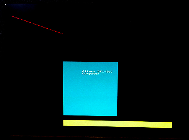
the program segfaults. The image to the left shows one update frame (at 320x340 resolution)..
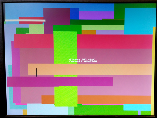
 The code was modified to write random rectangles. The write-rate is too fast to see, but the colors are nice.
(at 320x340 resolution). Colors are 16 bit: top 5 bits red, middle 6 green, lower 5 blue.
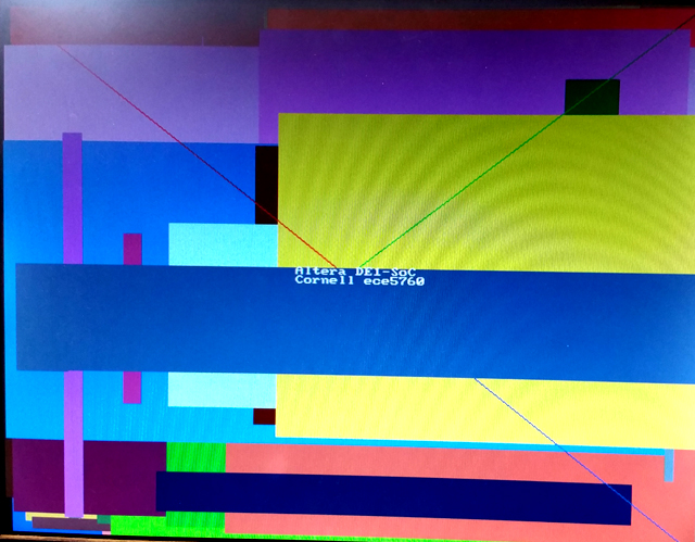
--Converting DE1-SoC_Computer_15_1 to 640x480
The directions written by Shiva Rajagopal for Qsys 640x480 converstion worked for this system. The span of the addresses in the virtual-to-real memory map had to be doubled. and, of course, the addressing and colors of pixels had to be modified in the main program.
The size of the character buffer was not changed. The color encoding is
now 8-bit with top 3 bits red, next 3 green, lower 2 bits blue.
VGA_line(0, 0, 320, 240, 0xe0) ; // red 3-bits
VGA_line(639, 0, 320, 240, 0x1c) ; // green 3-bits
VGA_line(639, 479, 320, 240, 0x03) ; // blue 2-bits
 Bruce Land
