Close
0%
0%

Diabetic Infusion Set Reminder

Simple on-desk reminder of infusion set lifetime and replacement cycle.

Similar projects worth following
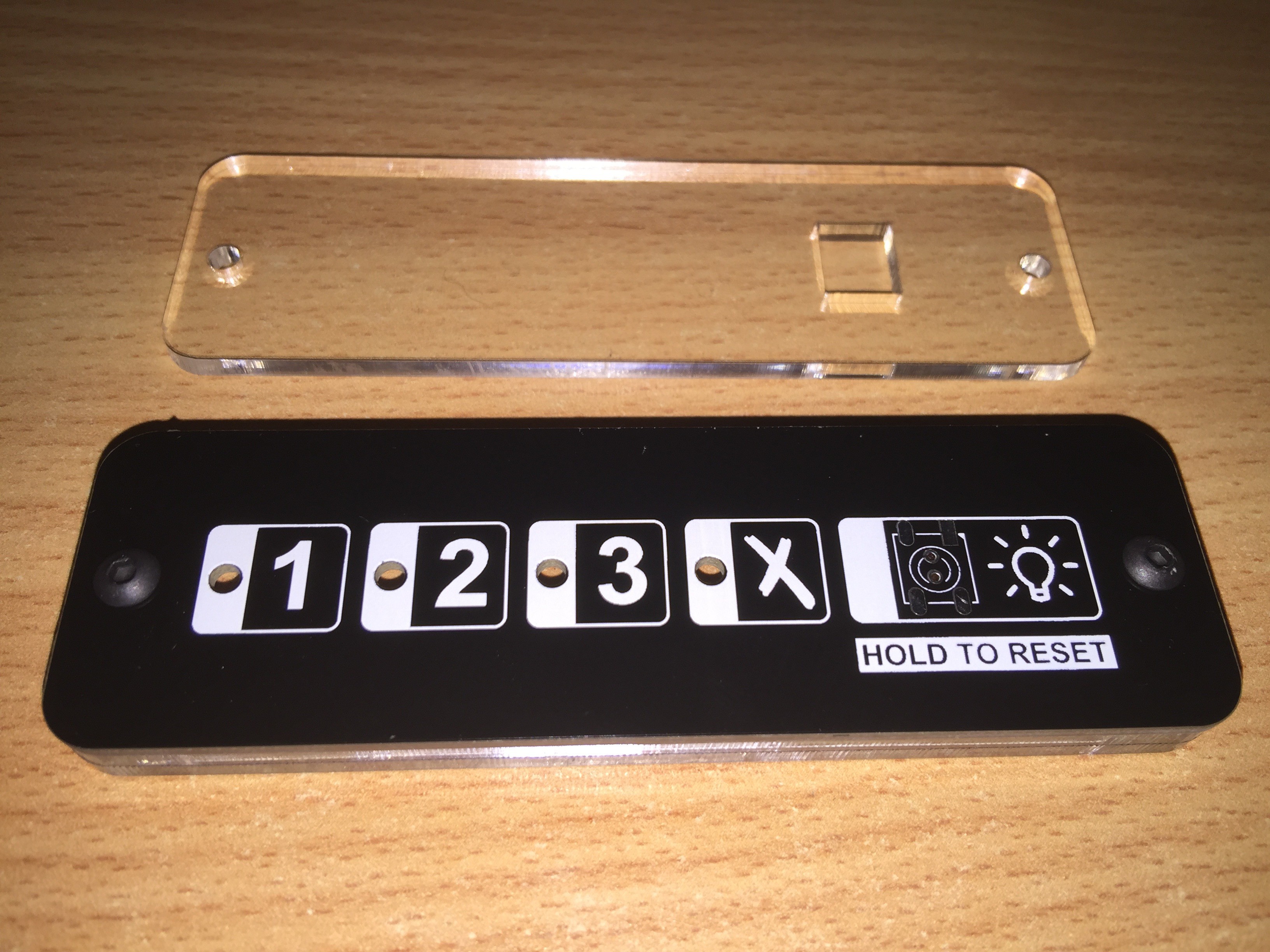
Simple timer device that indicates number of days since last reset. LEDs indicate Day 1, Day 2, Day 3, and Replacement Required. Coloured Green, Yellow, Orange, and Red for easy viewing at a glance.

Powered by an MSP430 operating from a CR2032 coin cell with a 32.768kHz watch crystal keeping time. LED's blink briefly every 15mins to keep power consumption at a minimum. Pressing the button momentarily will light up the LEDs for 5 seconds so the current state can be viewed at any time. Holding the button down for 5 seconds will reset the timer to Day 1.

As a long-time diabetic, I finally made the switch over to an insulin pump. Part of using a pump means changing infusion sets periodically. An infusion set consists of a tiny tube inserted under the skin, with a plastic piece that connects to a detachable piece of tubing which connects to the pump. These are meant to be replaced every 2-3 days. Beyond the third day, the skin around the infusion site begins to scar and can significantly reduce the absorption of insulin.

Being something that I do so often, I tend to forget exactly when I last changed it. So I wanted something simple to indicate how long the current infusion set has been in, and when I need to replace it.

This project is a simple battery operated device that will sit on my desk, bed side table, or wherever. 4 LEDs indicate Day 1, Day 2, Day 3, and Replacement Required. They will be Green, Yellow, Orange, and Red to make it clearer at a glance.

MSP430G2201 was chosen because it was dirt cheap ($0.43 AUD), was low power, and supported a 32.768kHz watch crystal as the external clock crystal. The MSP430G2001 is cheaper again ($0.32) but has less program memory. However, I might not need the extra flash in the 2201 anyway.

I wanted the front panel to be totally clean so I had a nice silk-screen overlay. This meant no vias or through hole components. Some juggling of IO pins used for each LED and the switch meant I could do the whole thing single sided. The pushbutton switch on the front is routed to the back with a couple of vias hidden underneath it.

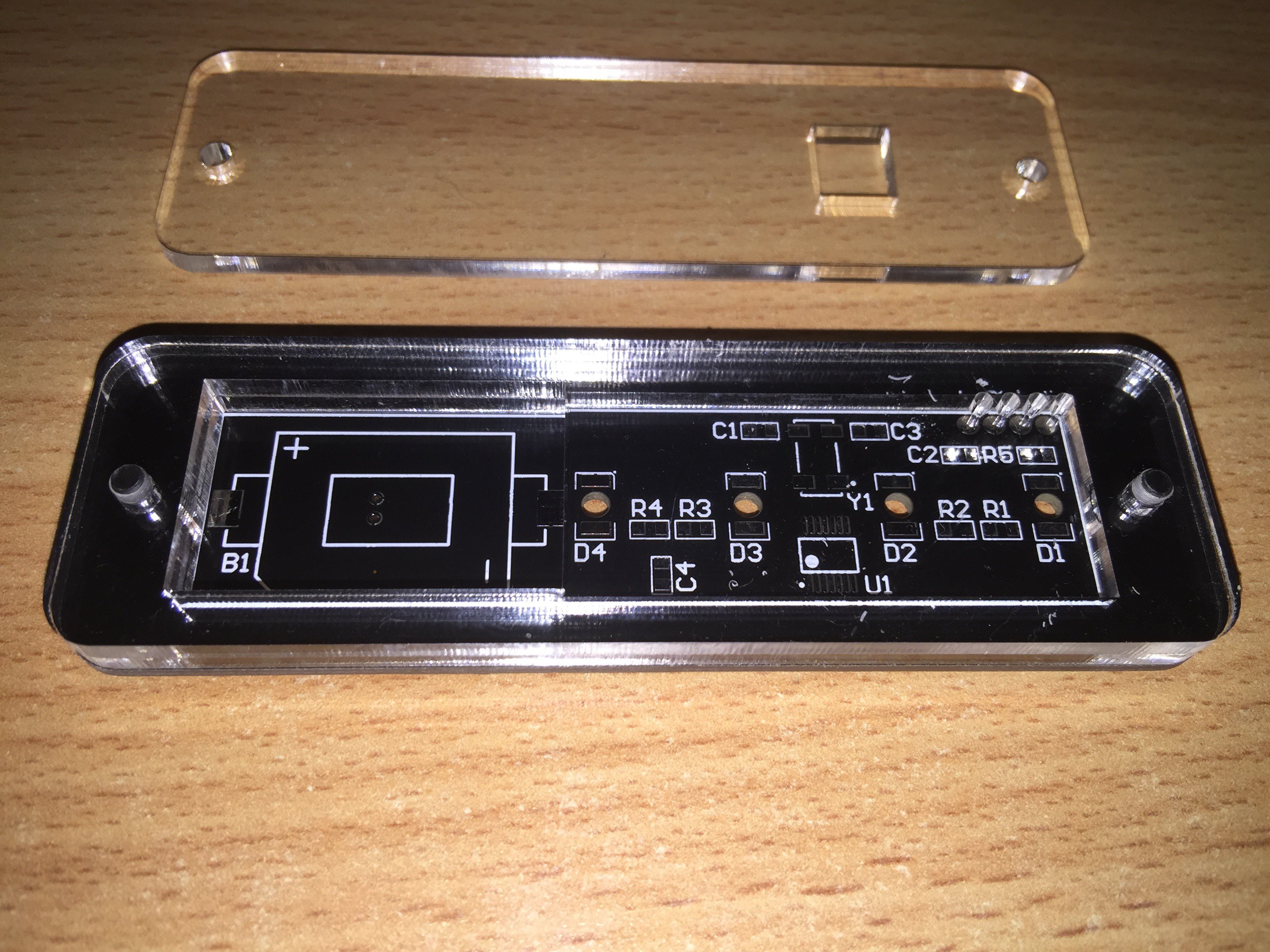
I am having a case laser cut out of acrylic at Elecrow (who are also doing my PCBs). They use 2.8mm acrylic. The case consists of the front piece, a middle spacer, and a back piece. The coin cell holder sits just below the surface of the back piece. The back piece has 2.5mm holes while the rest have 3mm. I'll be using 10mm long button head M3 bolts to hold it together. The 2.5mm holes will be tapped with threads. 2.8mm x 3 = 8.4mm. Add 1.6mm PCB and its 10mm thick. Perfect.

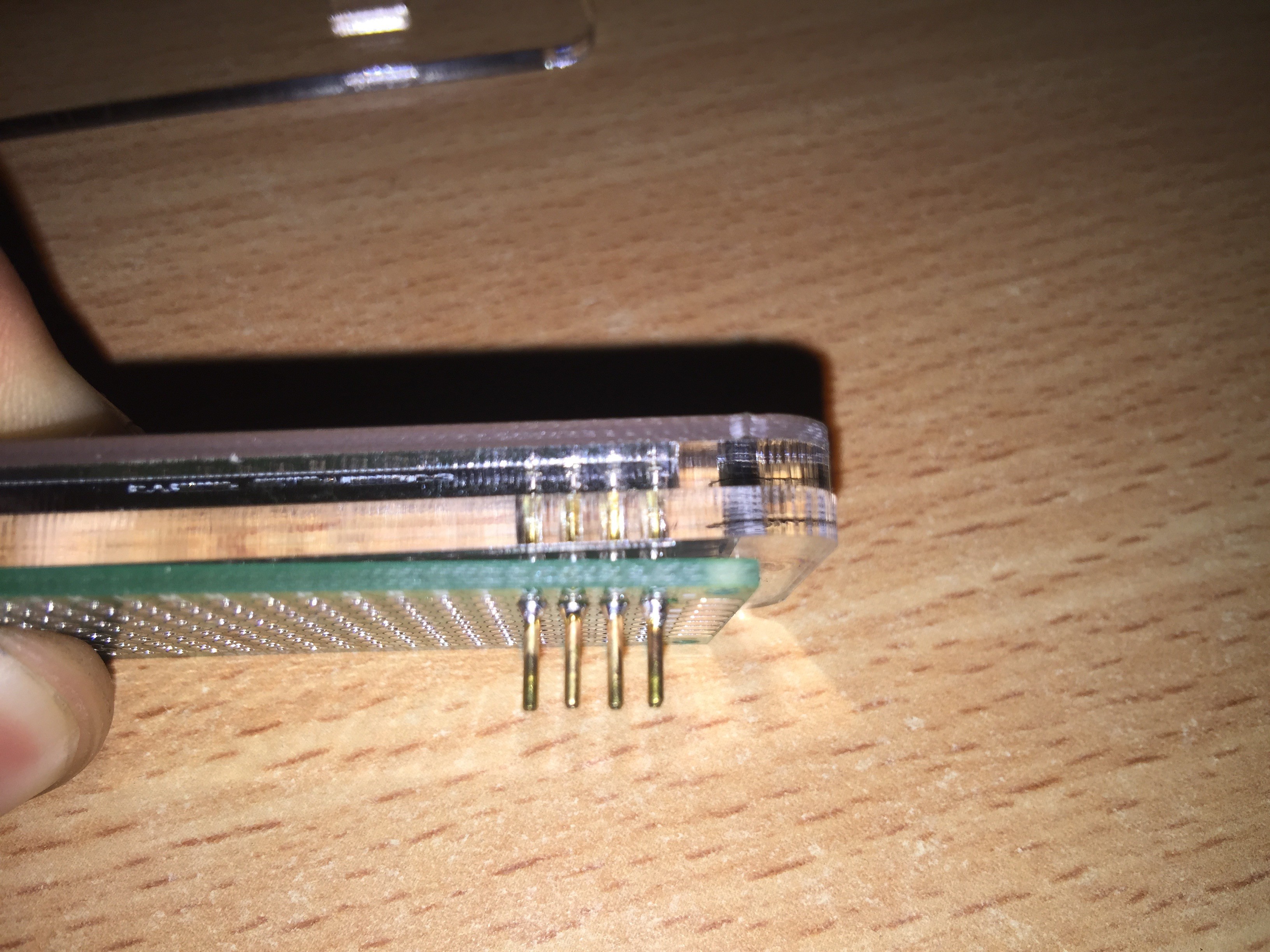
Four small holes in the back panel allow for pogo pins to reach through and make contact with the programming pads. The MSP430 is programmed via SPI BY WIRE. So just Data/Clock/VCC/VSS.

LEDs are OSRAM Reverse Mount Gullwing TOPLED RG series. Not dirt cheap but easy to mount.
  • 1 × MSP430G2201 MSP430 Low-cost Low-power 16-bit Microcontroller
  • 1 × CH28-2032LF Multicomp CR2032 SMD Mount Coin Cell Holder
  • 4 × Osram TOPLED RG Reverse Gullwing LEDs
  • 1 × ABS25-32.768KHZ-T Abracon 8x3.8mm SMD Watch Crystal
  • 1 × R0805 Various 0805 Resistors

View all 7 components

  • A few months later...

    David Ogilvy06/17/2016 at 13:50 0 comments

    So i've not really done any work on this since I assembled a couple of test units. I've been using one daily for the last few months and it's been incredibly handy. Quick and easy to use, does the one thing it's meant to do well - perfect.

    Sometimes I feel products can be overcomplicated. Do one thing and do it well.

  • Initial Testing

    David Ogilvy03/29/2016 at 14:56 0 comments

    Quickly hand soldered one together - SMD parts on pads not designed for hand soldering is fun... It's not pretty but it works!

    Had some issues with the 100nF capacitor on the reset pin (I should really look up what value it should be...) so I just removed it, otherwise the programmer wouldn't detect it. It seems to work fine without the cap so I'll just leave it out. Same with C1 and C3 which are loading caps for the clock crystal. The MSP430 has built in configurable capacitance which is enough for the crystal I'm using.

    Currently running it at 1sec = 1min accelerated speed so it can run through the full 3 day cycle in a matter of hours for testing.

    It will be interesting to see how long the battery lasts in normal usage. I used 230ohm resistors to limit the current to under 5mA. WIll properly measure the current at some point, and tweak values to get an even brightness from each LED.

  • PCB & Plexi Case Arrival

    David Ogilvy03/29/2016 at 12:17 0 comments

    I initially paid for EMS shipping for my order from Elecrow, but for some reason, customs/EMS Post rejected the package and sent it back to elecrow after a week. Elecrow were very helpful after I contacted them, and had it re-shipped via DHL. The package arrived within a couple of days, so from now on I'll spend the little bit extra for DHL over EMS.

    I quickly tapped M3 threads into one of the back pieces, and did a dry fit of all the pieces. I quickly realised the holes on the front piece were not aligned properly. Turns out I'd misplaced them 1mm too high on my cad design / DXF file... oh well. I want to make the back piece much closer to the battery holder (now I actually have the physical holders I can confirm dimensions - the joy of buying random things from Aliexpress without part numbers or datasheets).

    My idea to use pogo-pins for programming through some well placed holes in the case turned out well. Elecrow's laser cutting service has no issues cutting such tiny holes (approx 1.8mm if I remember correctly).

  • Launchpad Dev Platform & Current Measurements

    David Ogilvy02/29/2016 at 14:27 0 comments

    When I started this project, I knew I needed a low cost and low power microcontroller. All it really needed was a timer, some basic IO (5 pins), and the ability to use a watch crystal. Looking around my lab/study, I found some old MSP-EXP430G2 Launchpads. The kit includes an MSP430G2211 which is close enough to what I will be using (it's in the same family, and has analog comparator functions that the G2201 doesn't have, otherwise the same chip). The pin headers connecting the debugger section to the target section came in handy for taking power measurements.

    Using my trusty Dave Jones uCurrent Gold, and a Keithley 2000 DMM, I was able to take measurements in various states.

    Running the core off the internal oscillator (DCO), which runs at approximately 1 MHz, with a /8 divider, results in a core clock frequency of 125kHz. Running current is 100uA at this frequency.

    Running the core off the external watch crystal, 32.768kHz, with a /8 divider, results in a core clock frequency of 4.1kHz. Running current is 6uA at this frequency. However, I had some issues where it would boot up and run off the DCO, because the LFXCLK wasn't ready yet. There's an interrupt that occurs when LFXCLK fails, which I could use to then kick it back into low frequency mode. However, the device only runs in full power mode for a few seconds at a time, so I didn't bother. DCO it is.

    In Low Power Mode 3, with the internal timer running off the 32.768kHz external clock, with interrupts enabled for the button, current consumption was a measly 600nA.

    I have yet to decide on resistor values for the LEDs, but will be looking to keep the LED current around 2mA or less to reduce battery power consumption. A quick calculation shows I should get 6-12months of runtime easily with the occasional manual viewing of status.

    FYI: If you are using Code Composer Studio, and haven't tried out GRACE yet, do it. It's super easy to setup chip peripherals using a GUI. I had the timer, IO pins, clock sources, etc all configured in no time using GRACE.

View all 4 project logs

Enjoy this project?

Share

Discussions

Similar Projects

Does this project spark your interest?

Become a member to follow this project and never miss any updates