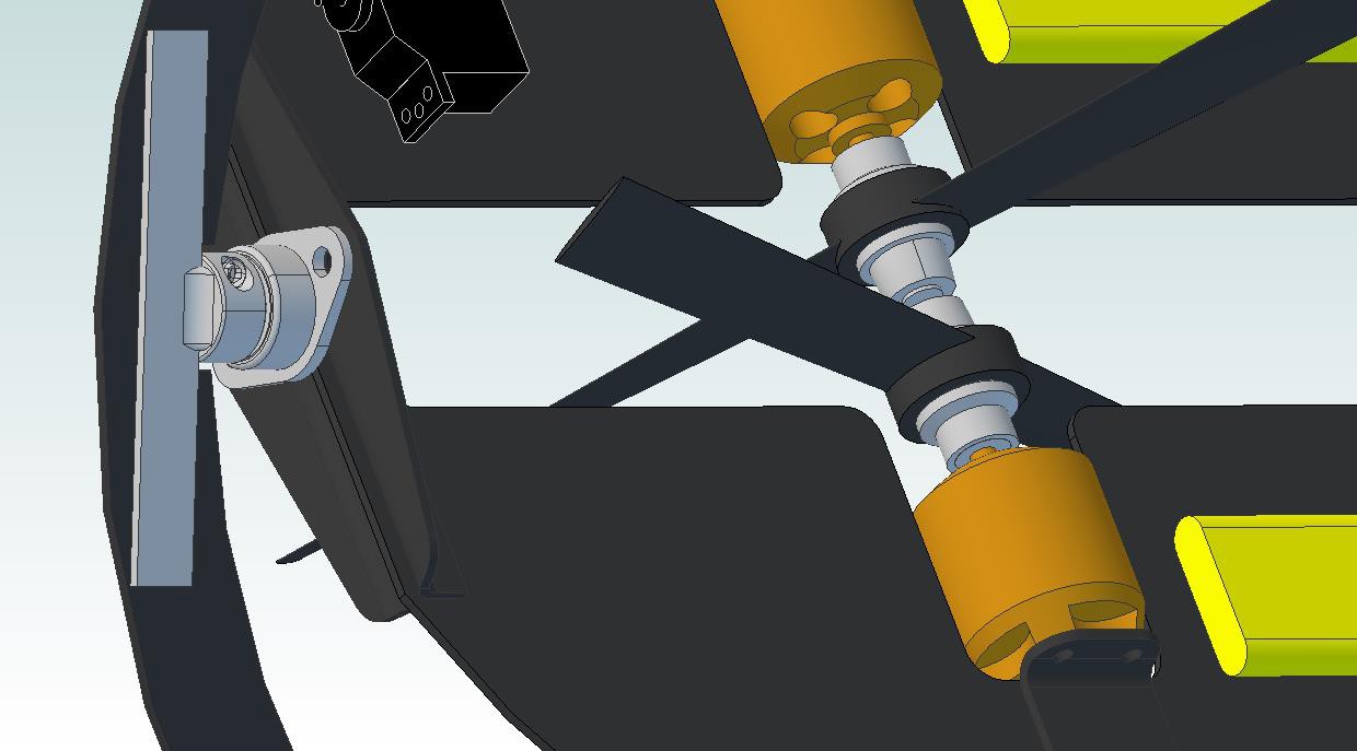
Now that I've got some parts in hand, I figured it was time to increase the accuracy of the solid model. If you're interested in the actual part files, check the Dropbox repository (and let me know if you need a non-Cubify format); we're on to version 05 at this point. My revision control scheme isn't terribly sophisticated; when I get sick of making changes to a model, I pretty much copy the folder and create a new version.

A few notes, as usual:
- Since I've got them on my desk, I measured up the brushless motors, props (and associated rotating hardware), and ESCs; their models are accurate in critical dimensions to ~0.1mm or so (although my calipers are pretty crappy).
- The bearings and shaft couplings are solid models downloaded from McMaster. Note that the shaft couplings have a welded-on aluminum bracket; I'm an almost-passable welder on reasonably thick carbon steel, but I sure do suck with aluminum so I'll be getting this done somewhere.
- The motor brackets and bearing brackets are made from 1.6mm CFRP angle stock. Ideally, I'll get these bits waterjet cut so they look pretty, but I might just trim 'em myself to keep cost down.
Next steps in the solid model:
- Theta servo linkage
- Rho bearings and brackets
- Rho servo shaft and mounting scheme
- Frame improvements
The waterjet guys do a batch every 2 weeks or so; I'm shooting to finalize the design by the end of May, order the CFRP plates, and hopefully have cut parts ready to assemble by the third weekend in June. I'm doing everything I can to keep stuff inside the standard plate dimensions to keep cost down; at this point, I'll likely need one 24"x48" 1/32" sheet and one 12"x12" 1/16" sheet. Before anything gets ordered, real-world thrust measurement will happen so I can improve the accuracy of my weight target.
Comments, as always, are welcome.
 zakqwy
Discussions
Become a Hackaday.io Member
Create an account to leave a comment. Already have an account? Log In.