Okay, so we're not quite hovering yet... but I got one of the servo mounts and linkages wrapped up tonight, and I'm satisfied with its functionality. First, the test video:
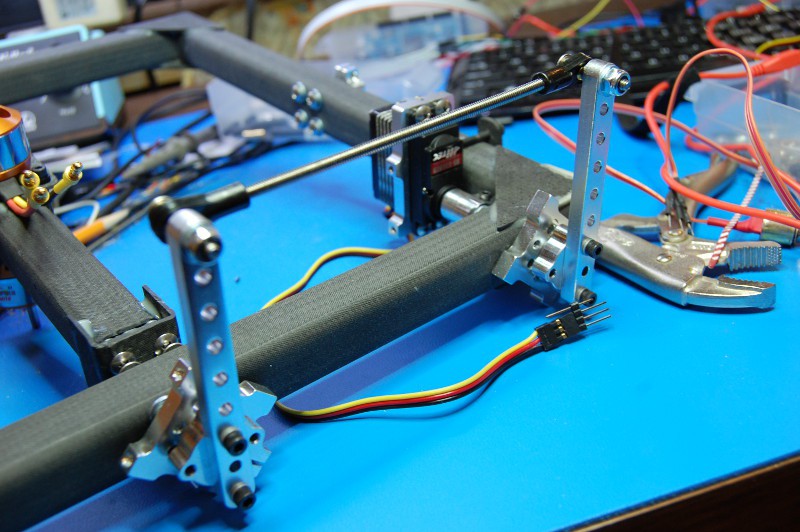
A few detail pictures:
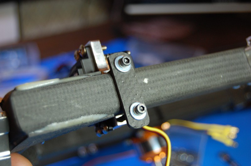
Cut, drilled, and shaped a 2.4mm thick piece of CFRP as a backing plate for the servo mount:
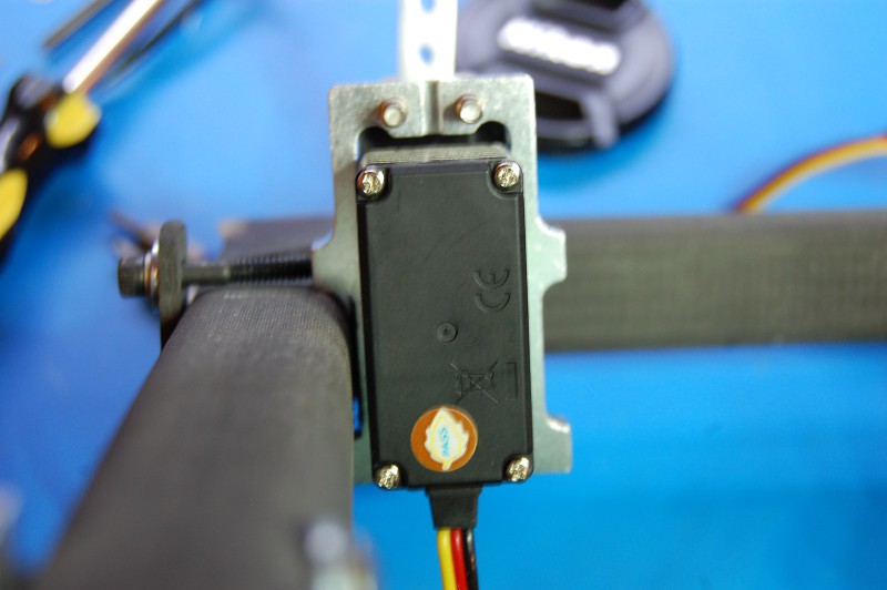
Drilling the servo bearing mounting holes without a drill press from one side (since everything is glued up already) lead to some hilariously bad servo alignment. In the blurry shot below, you can see how much material I had to file off the left side of the servo mount to get the shaft to turn freely:
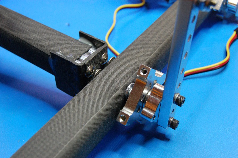
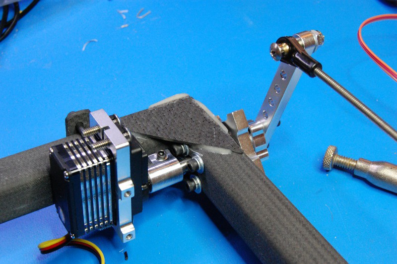
A few linkage detail shots. Only thing to note here is the inordinate amount of time I spent hacksawing bolts down to size. Note to self: buy the right length bolts next time. At least they weren't too short:
As I mentioned in the video, the outer servo will have a much harder job; it has to move the whole mess you see above, and I'm guessing I'd overload the servo geartrain without some ramping. Either way, this feels like a good start.
- Zach
 zakqwy
Discussions
Become a Hackaday.io Member
Create an account to leave a comment. Already have an account? Log In.
Are you sure? yes | no
The phrase 'be careful with twitchy movement' actually made me think a bit more about GimbalBot's instrumentation; reducing the magnitude of the shocks transmitted up the frame to the IMU due to fast servo movement will help with accelerometer and gyroscope noise.
Great points, thanks for your input!
Are you sure? yes | no