It's time to get the testing plan in order. I have been quite tempted by my brand-new 4S/5000mA battery; I think this could provide the 'oomf' needed to produce plenty of thrust to get off the ground. However, I don't want to burn out the stators; I've already got a cooling plan in place, it's just time to execute now. My original 3D printing plan didn't work out, so I just sent an order out to Shapeways. I haven't used them in the past, but the price wasn't bad and I should have parts in hand by September 5th or so.
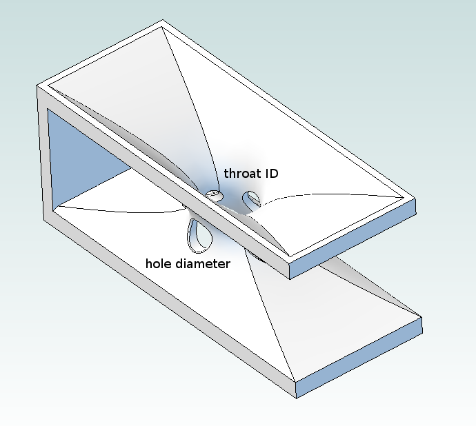
Pulling back on the printing gave me a bit of time to think about the parts. Rather than testing the angle and length of the venturies, I ordered four different parts that all have the same cross section; I'm designating them 3x8, 3x10, 4x8, and 4x10. The first number is the diameter of each of the four holes; the second number is the ID of the throat at its narrowest point. Why? Well.. I can try angling airflow a bit with glued-on (or clamped-on) CFRP tabs. And varying the length of the venturi itself is a one-way proposition; once I cut the slots in the motor mount to fit the larger pieces, I'll have trouble reversing the procedure if the new parts don't perform as well.

I had a lot of other ideas, but I wanted to be able to assemble a basic testing matrix. Adding new characteristics tends to drive the number of models needed to crazy levels, and I'm worried I'll get a whole pile of parts back that all have the same problem; after all, this is my first 3D printing job. So four venturies and six (two extra) motor ducts will do for now. You can find the 3D models and *.stl files in the GimbalBot Dropbox directory, or download the files from Shapeways (you should be able to find them by searching for the term 'GimbalBot' on their site).
So I've got a bit over a week to get ready for some rigorous GimbalBot tests. What's left to do?
- install the new pillow block bearing on the thrust testing rig
- build and test motor tachs (parts should be here in a few days)
- figure out a good way to repeatably measure motor temperature (I've got TCs, but I need a bit of circuitry which should be here with the tach parts)
- figure out how to datalog the cheap-o electronic scale (I've made some headway here but still can't get great resolution--that's a subject for another post)
- Enjoy Labor Day Weekend up north with the family, so much of this won't get done until next week
My goals for testing are to produce the following curves with various propeller, motor cooling system, and fan duct configurations:
- RPM vs ESC PWM signal
- Thrust vs RPM
- Thrust vs Current
- Stator Temp vs Run Time (cold start, constant RPM)
- various temp measurement points
- various RPMs
My current current shunt (hah..) can't handle both motors simultaneously, so I might run single-motor tests for some of these. Or I'll get another shunt. Or something.
I'll also try to formalize this a bit. You know, a bit of background, a brief testing plan, a discussion of uncertainty, some crappy whiteboard diagrams, and a few poorly-grounded hypotheses.
Woo science!
 zakqwy
Discussions
Become a Hackaday.io Member
Create an account to leave a comment. Already have an account? Log In.