 zakqwy
TL;DR: back to the drawing board. Or maybe it's time to try for a hover test, and tell thermal issues to go to hell?
I ran seven tests this evening. Main changes since yesterday:
- Increased the motor pwm signal to 110 degrees. I wanted to put some heat into the coils!
- Changed the program around a bit--now the button starts a 120-second test.
- Tried to be a bit more consistent between runs--I started each new run once the temp hit ~30 C.
All data is in the repo; here's the summary graph:
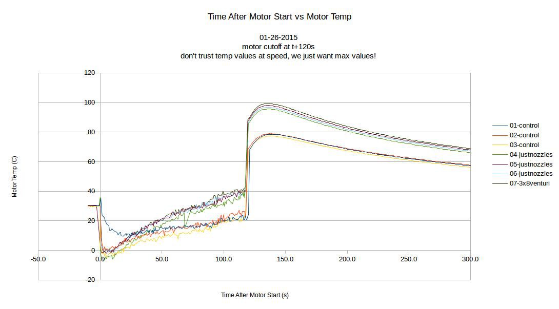
So--what's up with the jagged lines during the actual motor run? Well... seems when I went from 100 degrees to 110, the TC signal got totally garbled. I backed off to 100 degrees and the problem seemed to go away; however, the presence of the 'NAN' (not a number) results from the MAX board makes me more suspicious of the temp data. Hence the subtitle on the graph: "don't trust temp values at speed, we just want max values!" I made a habit out of unplugging the ESC power supply as soon as the run finished, which helped keep the post-run ramp up to Tmax nice and clean.
Okay, enough chitchat. Maximum motor temperature values for each run:
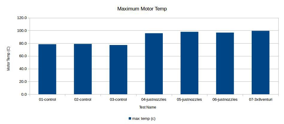
So... max temp increased by 20 C or so going from the control group to just using the nozzles. Worse, the venturi didn't seem to improve anything; I ran out of time before rounding out the tests, but I'm guessing the difference between the nozzle runs and the venturi run isn't statistically significant. Clearly, the motors do better without cooling ducts, and it doesn't seem like the venturi did anything!
Other details: I measured current (via a shunt) and voltage going into the ESC and it remained almost completely stable. Thrust dropped by 50-100g for the last four tests; maybe the motor overheating caused issues here? I'm not surprised that the venturi test dropped the thrust a bit, since the 3D printed insert does cast a bit of a 'shadow' downstream of the propeller.
So what's the takeaway here?
- Lots of smart people probably spent a lot of time designing the cooling system for the motors, so it's probably pretty good as-is. Keep it simple, stupid!
- I learned a lot about serial data acquisition on the cheap, thermocouple noise, 3D printing (first 3D printing project!), and... well, you know how it goes when an experiment doesn't work as planned. I've learned this before, but I was reminded about how important it is to try out ideas even when there's a good chance they will fail. It's also just as important to share the results with the world--if nothing else, maybe this will add a data point for someone else trying to improve the cooling system for their quad.
I'll put it to a vote--if you've made it this far reading, what do you think I should do? Put GimbalBot back together and see if it will fly?
Discussions
Become a Hackaday.io Member
Create an account to leave a comment. Already have an account? Log In.
Go for it. Keep up the good work!
Are you sure? yes | no
Thanks Mom!!
Are you sure? yes | no
..don't forget to take your jacket.
Are you sure? yes | no
Definitely heard that a few times when I moved up to MN.
Are you sure? yes | no
I always vote for flying, course I haven't always had the best luck :)
Are you sure? yes | no
I am not sure how you have your thermocouple mounted, but would something like this work? http://www.mouser.com/ds/2/609/TMP35_36_37-246343.pdf with some heatsink compound on the flat surface and having it pressed up against the part that gets hot. Possibly put a blob of RTV over the sensor after it has been coupled with the part.
Are you sure? yes | no
I'm referring to the TO-92 package.
Are you sure? yes | no
I like that idea--mostly because it seems like it would improve my signal:noise ratio by a few orders of magnitude! Type K thermocouples run around 41 uV/C (per Wikipedia); the devices you linked to are 10-20mV/C depending on the model. I should really scope the TC line while the motors are running, but that could be enough to give me a stable signal. I could also ditch the MAX breakout board and take the voltage signal directly into an analog input.
Are you sure? yes | no
Right now TC mounting is a bit tight; most of the motor housing rotates around the stator, so the element is sandwiched in a filed groove between the motor base plate and chassis (see previous update for a picture). However, I could probably figure something out with the unit you listed. Thanks for the suggestion, definitely worth investigating.
Are you sure? yes | no
It might also work to cut the heat shrink off of the wires going into the stator, slide the tmp35 in as close to the stator as possible and shrink a new piece of the heat shrink back down over all of it. The temp value may not be true, but you could induce a heat failure and see what your temp reading is, assuming all motors fail at a similar point.
Are you sure? yes | no
Can you add code that will allow the gimbalbot to fail gracefully if it starts to get hot? Try to bring itself down slowly if the temp reaches a certain point. Anyway, I vote fly it.
Are you sure? yes | no
I like that idea--my primary concern is with signal integrity. The temp data is super unreliable and noisy when the ESCs are powered up. Thermocouples use millivolt-level signals which are pretty sensitive to noise; I could see an RTD improving this a bit.
Either way, that's really more in the realm of untethered flight... we're not quite there yet. Great idea though. And your vote has been tallied.
Are you sure? yes | no