-
Planning for a few instrumented tests
08/27/2014 at 05:09 • 0 commentsIt's time to get the testing plan in order. I have been quite tempted by my brand-new 4S/5000mA battery; I think this could provide the 'oomf' needed to produce plenty of thrust to get off the ground. However, I don't want to burn out the stators; I've already got a cooling plan in place, it's just time to execute now. My original 3D printing plan didn't work out, so I just sent an order out to Shapeways. I haven't used them in the past, but the price wasn't bad and I should have parts in hand by September 5th or so.
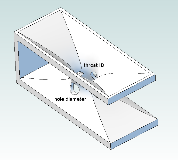
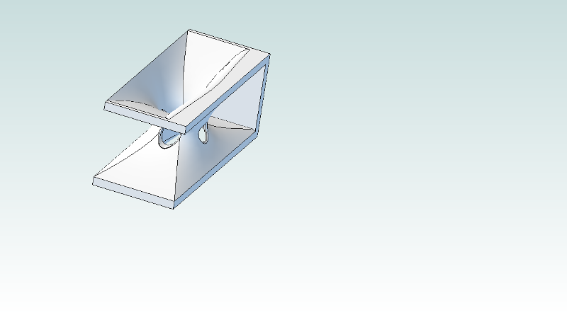
Pulling back on the printing gave me a bit of time to think about the parts. Rather than testing the angle and length of the venturies, I ordered four different parts that all have the same cross section; I'm designating them 3x8, 3x10, 4x8, and 4x10. The first number is the diameter of each of the four holes; the second number is the ID of the throat at its narrowest point. Why? Well.. I can try angling airflow a bit with glued-on (or clamped-on) CFRP tabs. And varying the length of the venturi itself is a one-way proposition; once I cut the slots in the motor mount to fit the larger pieces, I'll have trouble reversing the procedure if the new parts don't perform as well.
![]()
I had a lot of other ideas, but I wanted to be able to assemble a basic testing matrix. Adding new characteristics tends to drive the number of models needed to crazy levels, and I'm worried I'll get a whole pile of parts back that all have the same problem; after all, this is my first 3D printing job. So four venturies and six (two extra) motor ducts will do for now. You can find the 3D models and *.stl files in the GimbalBot Dropbox directory, or download the files from Shapeways (you should be able to find them by searching for the term 'GimbalBot' on their site).
So I've got a bit over a week to get ready for some rigorous GimbalBot tests. What's left to do?
- install the new pillow block bearing on the thrust testing rig
- build and test motor tachs (parts should be here in a few days)
- figure out a good way to repeatably measure motor temperature (I've got TCs, but I need a bit of circuitry which should be here with the tach parts)
- figure out how to datalog the cheap-o electronic scale (I've made some headway here but still can't get great resolution--that's a subject for another post)
- Enjoy Labor Day Weekend up north with the family, so much of this won't get done until next week
My goals for testing are to produce the following curves with various propeller, motor cooling system, and fan duct configurations:
- RPM vs ESC PWM signal
- Thrust vs RPM
- Thrust vs Current
- Stator Temp vs Run Time (cold start, constant RPM)
- various temp measurement points
- various RPMs
My current current shunt (hah..) can't handle both motors simultaneously, so I might run single-motor tests for some of these. Or I'll get another shunt. Or something.
I'll also try to formalize this a bit. You know, a bit of background, a brief testing plan, a discussion of uncertainty, some crappy whiteboard diagrams, and a few poorly-grounded hypotheses.
Woo science!
-
#ExternalMotivationDeemedUnnecessary
08/25/2014 at 23:09 • 2 commentsThe newest tag says it all: GimbalBot missed the cut, but I will still finish this one through to the end. I hope all the other Round One DQers do the same. Don't finish your project for space--finish your project for you!
On a more serious note, a hearty congratulations to all of the teams still in the running. It's been a great ride, and I know you will all make great things come of this unique event. We're all watching now!
[... and on that note, I'm off to the MN State Fair, where I'll have all sorts of fun not being hunched over my soldering iron for the first evening in some time... ]
-
Fannington McDuctsworth
08/23/2014 at 03:57 • 3 commentsIn a previous post, I mentioned that I wanted to build a duct around the propellers in an attempt to increase their efficiency. I located a company that owns a 9.63" mandrel for fabricating CFRP tubes out of pre-preg, so I ordered a chunk intending to finish up the design when it showed up. UPS dropped the tube off this afternoon, so I spent the evening modifying the CAD model and fabricating the duct sections.
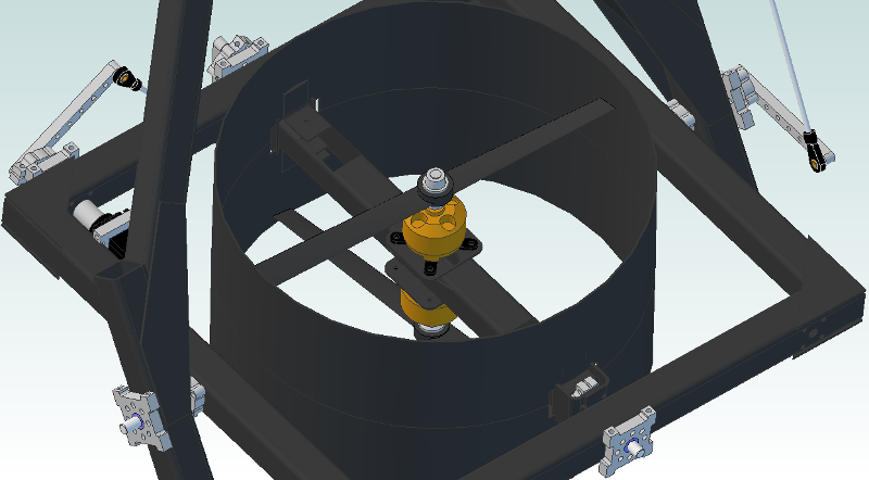
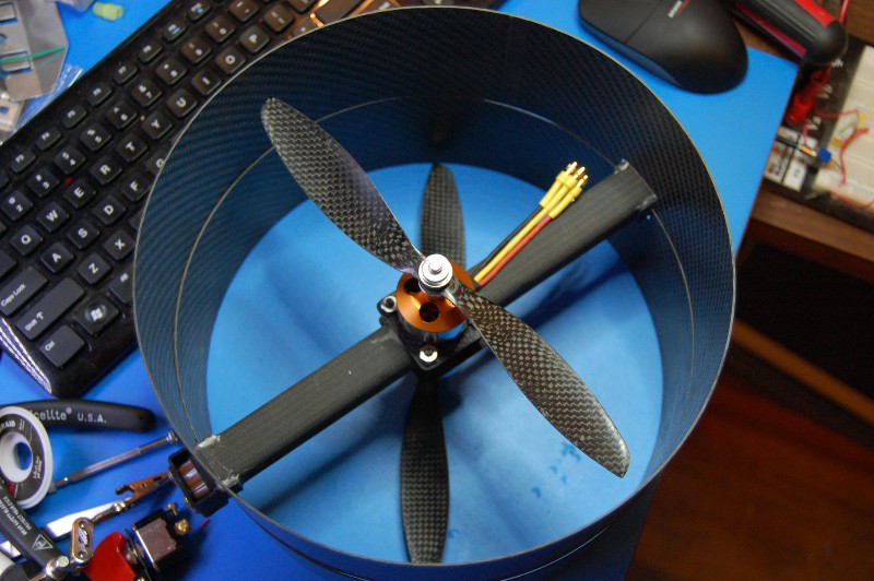
The duct consists of two lengths of the tube notched to accommodate the motor mount and bolted on using a few CFRP brackets. I thought about building the duct out of a single length of the tube, but the motor mount plates would require a large clearance hole (and it would make the motors tough to work on). Length is limited by the range of motion of the propellers; since I'm back to using 9" units, I was able to make the duct extend roughly 1 cm beyond the top of each prop:
![]()
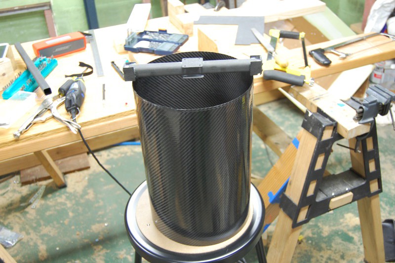
Here's the tube as it arrived with the motor mount sitting on top. It's a bit long with one slightly rough end, as expected:
![]()
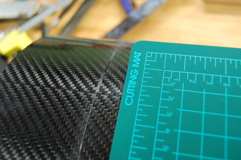
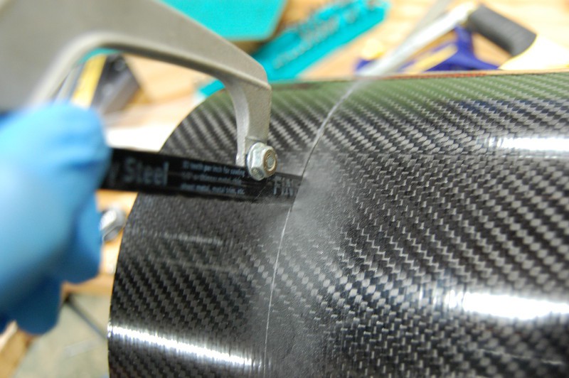
I used a square to mark the tube in several places along its circumference, then scribed a line using a bent cutting mat as a guide. I started cutting the tube using a steel-bladed hacksaw, hoping to minimize blade kerf to save material:
![]()
This was ridiculously slow going. I made it about six inches, then did a bit of math in my head (9.6" * 3.14) and considered changing course:
![]()
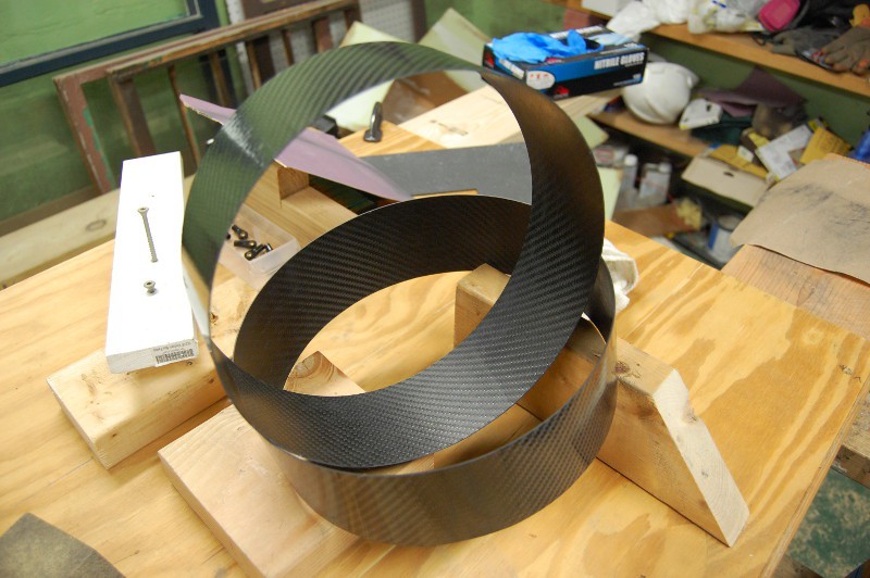
I decided to not worry about blade kerf and got the jigsaw out. Great choice. A bit of sanding and I had two 75mm long tubes:
![]()
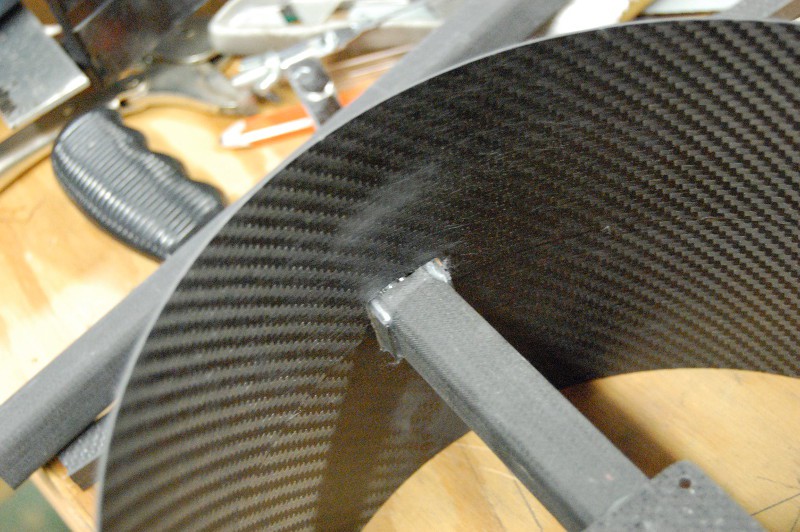
I outlined one of the tubes on the plywood and did a bit of geometry to find its exact center, then used that to mark the location for a few notches. I also removed a bit of extra bracket material from the motor mount so everything fit:
![]()
The props have roughly 6mm of clearance on each side, give or take. Getting that number tighter would probably improve the positive effects of the duct, but I was concerned about my ability to precisely locate the slots (and it's the size that was available, so I made do). I cut some brackets for mounting the duct to the motor mount but haven't glued them on yet; I'm going to hold off until I start on the motor cooling modifications (which are waiting on the rapid prototyped parts) so I can epoxy everything at once. When the whole assembly is together, I'll probably use some tape to seal the gap up. In any case, here's where things stand for now:
Yup, it passes the "does it look cool" test. More to come!
Zach
-
Hackaservo.io, part 6
08/20/2014 at 12:23 • 0 commentsTime for some closure with Part 6. Based on discussions in the comments and offline chats during the Hackaservo.io tangent, I decided to button the servo back up with its stock ~9k resistor. I realized that while I'm getting more comfortable working with surface mount stuff, I'm not well equipped to rework 0402-sized components on a densely populated board; I'm not saying it's a miracle that I was able to replace the resistor, but I'm going to hold off on opening that servo up again for awhile as it's back to working in its factory state. We'll see if I have issues with loop tuning down the road; if so, I have a much better idea of which resistors to change.
-
Motor Cooling, part 2
08/19/2014 at 03:04 • 5 commentsSeems that all GimbalBot posts come in 'parts' nowadays, huh? Sorry about that. Maybe I'll do some consolidation at some point. Doubtful.
I've sent five items off for 3D printing. And by that, I mean I've sent them to a good friend that has agreed to print them for me on his machine. Thank you, friend.
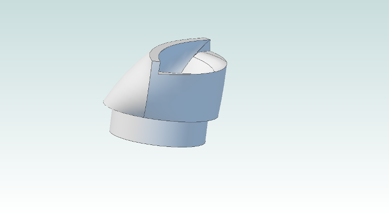
One duct... :
![]()
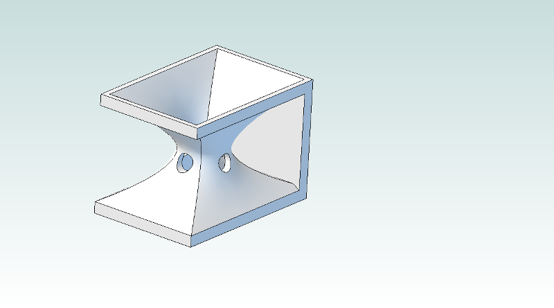
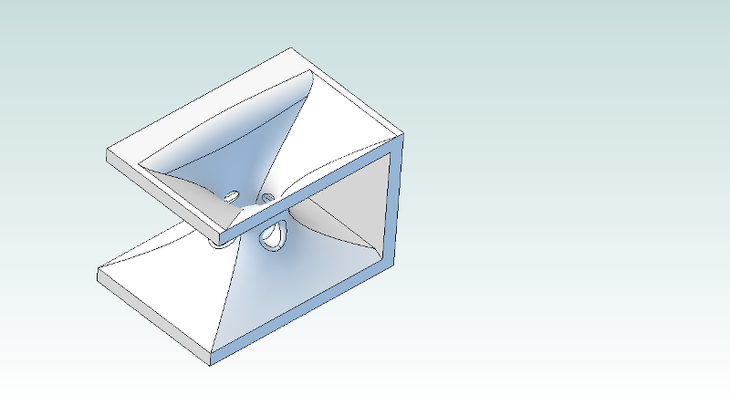
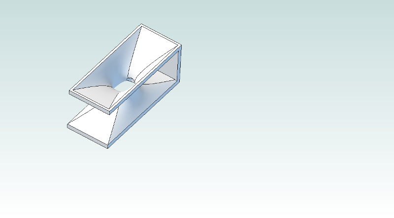
... and four venturi designs:
![]()
![]()
![]()
![]()
Two different lengths for the venturi models, 30 and 50mm. One pair are straight-on, the other pair are angled in an attempt to take prop wash in to account as discussed in the previous log. I moved the inlets down a bit so they're slightly downstream of the choke point, but otherwise didn't change much. Despite my claims about trying to size beta ratios and inlet diameters, those are pretty arbitrary.
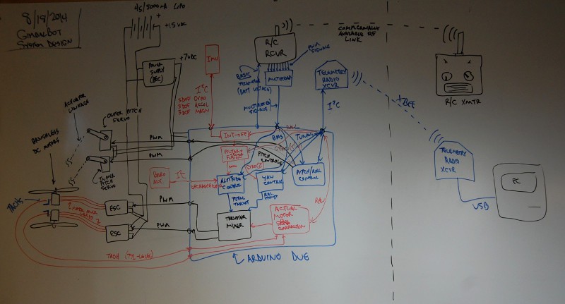
In the interest of complying with the HaD Prize Phase One Prize Requirements, I also put together a system diagram:
![]()
It's not terribly clear--diagrams definitely aren't my strong suit. I'll publish an updated digitized version on 8/20.
-
Motor cooling discussion
08/18/2014 at 14:13 • 0 commentsHad an offline discussion with a good friend (and extremely talented aerospace engineer):
[Friend]
Here's my two cents: I'd go with your venturi design. I think you'll have better luck pulling air through the motor in the same direction the propeller is pushing the air (if only for the top motor). The nozzles you had pictured in your post looked cool, but I don't think they'll help you too much because your flow field probably looks something like this: https://forum.solidworks.com/servlet/JiveServlet/showImage/2-373006-92361/Untitled.png
From my understanding, those nozzles are meant to have the follow go straight into them (like within a pipe or at the very front of an airplane). Your down-wash is going to be going all kinds of unpredictable directions. I'd just leave open slots and let the high velocity (low pressure) air go through the slots pulling the air near the motor through, helping to cool it. How big should the slots be? Maybe 1/3 the radius? There's a trade-off there. Too big and you lose structural strength. Too small and you'll get no cooling air flowing. There's also going to be some unquantifiable lift penalty. I'm not sure if lift is already an issue for GimbalBot or not.
You were right about the velocity increasing on the post-propeller flow as you go out radially. I think it would look more like part (b) of this picture though: http://energyresources.asmedigitalcollection.asme.org/data/Journals/JERTD2/26499/009104j.1.jpeg
The twist on airplane propellers is usually set based on the maximum lift to drag ratio for a certain flight speed and/or throttle setting; not to achieve a uniform down-wash velocity profile like pointyointment implied. Not sure how much thought was put in to your propeller twist by the manufacturer, but it's probably pretty good.
Good luck Zach! I'm excited to watch how GimbalBot progresses!
[Zach]
Thanks for your comments. I share the concern about structural integrity; I've got a lot of extra CFRP plate I can glue on to the sides of the motor mount if necessary which should help improve stiffness. We'll see how cleanly I can cut slots in the motor mount tube.
I think I'll probably put nozzles in either way; to be clear, when I say 'nozzles' I'm referring to the small duct that interfaces between the bottom of the motor and the top of the CFRP motor mount: https://cdn.hackaday.io/images/8226951407893975604.png
I suspect not sealing that gap could give me trouble by sucking in air below the motor, reducing the flow past the stator.
Agreed on the unpredictable down-wash. I'm guessing the flow below the propeller will be quite turbulent and also have a fair degree of 'twist'. Think I could design a venturi nozzle whose inlet is at an angle (say 30 degrees or so) to ideally capture the flow stream a bit more head-on?
Here's a thought: I could design a few different venturis and see which (if any) has the greatest effect on motor temperature, and run some baseline tests with the ducts closed and completely open. Fortunately, the parts I'm looking to print are small enough that they'll be cheap to rapid prototype.
Mind if I post our discussion on the comments section? I try to do that when I have offline conversations with folks, mostly so I can keep everything in once place (and hopefully so other people can contribute too).
Zach
[Friend]No amount of speculation beats a test. I think trying some different venturis is a great idea.
Feel free to post our conversation.
[Log]
I'm having some issues with Cubify Design producing *.stl files; once I get that sorted, I'll send the nozzles and a few different venturi designs off for rapid prototyping. -
Hackaservo.io, part 5
08/16/2014 at 13:00 • 0 commentsI did a bit of soldering last night:
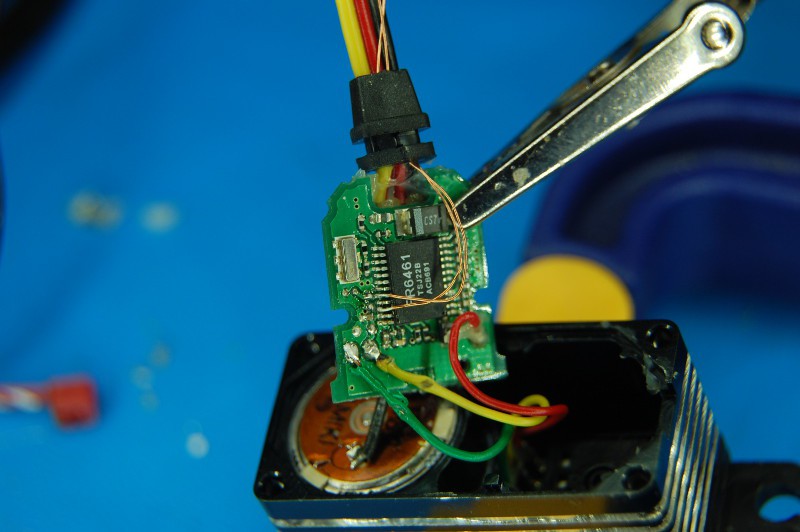
Magnet wire works really well. It's insulated and just about the right thickness for this work. I tried using other wire previously and it failed miserably. Highly frustrating. Someday I'll get a hot air setup; until then, my trusty WES51 will have to do. After soldering all this stuff together, a few dabs of hot glue secured the potentiometer wires and provided some strain relief to the new resistor taps.
A video showing the servo response with changing R1 values:
I misspoke a few times during the video; the mass attached to the pitch ring doesn't change, that's just an affect of gravity vs pitch ring angle. Also, this would have been easier if I actually had a reasonable potentiometer available from my junk collection; the trimmer you see on the board is a 1k unit, and the next closest device I had was 500k (!!!). Might be time to restock.
A few updates not related to the servo hackery tangent:
- Early on, I considered using a ducted fan for the thruster; they improve propeller efficiency by reducing tip losses. Commercially available units tend to be high-RPM low-diameter units designed to mount within the body of model fighter jets and the like; they produce ridiculous thrust velocities (great for scale F22s!) but not a great deal of thrust. Also, they're loud. So I abandoned the idea, figuring that I wouldn't be up for custom-fabricating anything. Times have changed; I located a CFRP shop that owns a 9.63" mandrel and seems to like small custom jobs. I'm having them fab up a 14" pre-preg tube in that diameter (14" was the same price as 12", $120). Once it arrives, I'll update the CAD model and fabricate a few brackets for the motor mount. With luck, that will increase my prop efficiency a bit!
- I'm going to finalize the motor cooling stuff and get the files out for 3D printing by tomorrow evening. I'll tweak the venturi sizing a bit. I'm also out of TC amps (the last one got used in a toaster oven reflow project), so I'll order a few more of those so I can quantify before/after performance.
- I plan to order a beefy pillow block for my thrust testing rig this weekend. They're cheap and readily available. The hilarious DIY plumbing bearing has led a good life, but it's time to retire that unit for something a bit stronger. My 4S/5000mA LiPo arrived earlier this week and I'm dying to give it a proper test.
- I haven't forgotten about tachometers (well, I did a few times, but that happens). I'm going to order the optoelectronic bits to put these together when I have the motor mount out for cooling duct installation.
- I'll probably redo my HaD Prize video, since a lot has happened in the meantime (I was halfway through frame construction when I filmed the current one). I'll also finish up the other requirements and update the Project Details section as appropriate. 8/20 is right around the corner!
In any case, I think it's time to get access to the other tuning resistor!
-
Hackaservo.io, part 4
08/15/2014 at 05:06 • 6 commentsAh, tangents. Sometimes educational, sometimes helpful, sometimes a colossal waste of time. Always enjoyable.
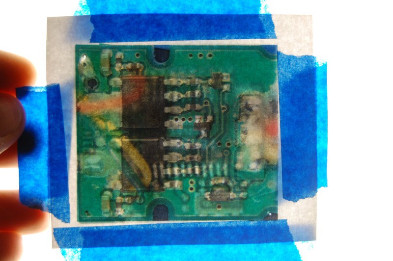
I decided to spend a bit more time getting higher quality images of the PCB; I ended up un-distorting the pictures, scaling them identically, printing them out, and taping them back-to-back in an attempt to get a better feel for via locations. It kinda worked:
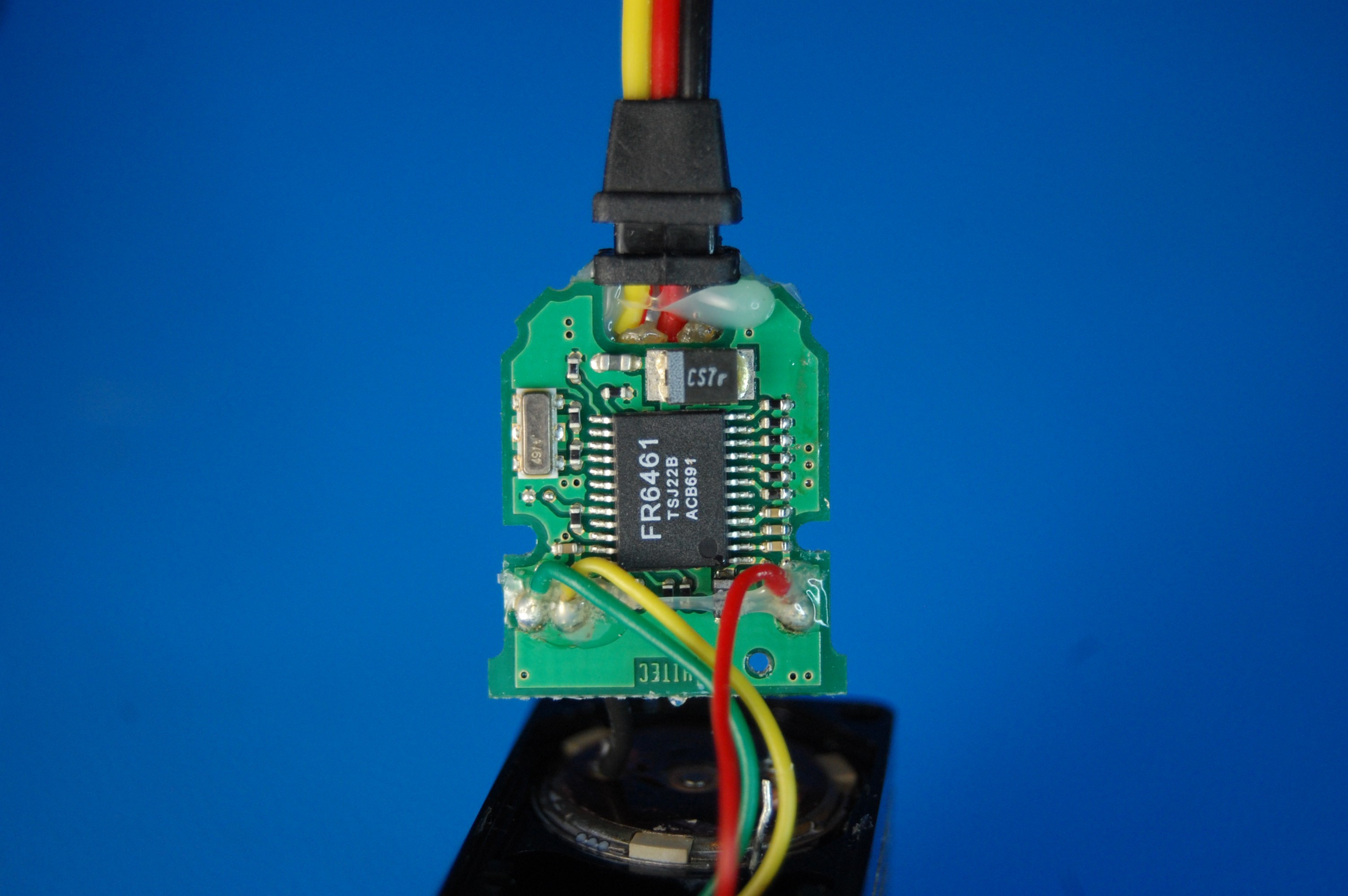
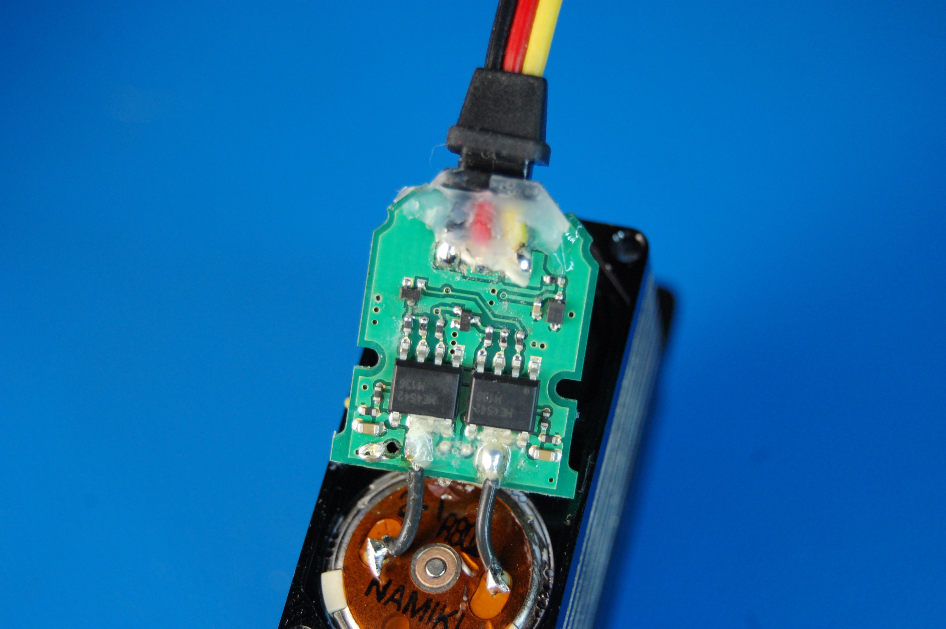
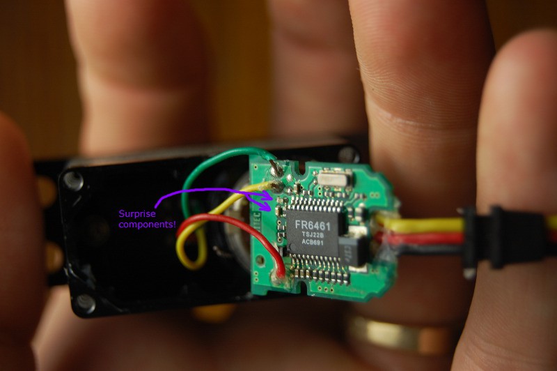
Probably not the best use of my time, but I built a nifty light source that should be handy for future photographs. In any case, I ended up spending quite a bit of time after the image manipulation bit with an X-acto knife, carefully scraping away the excess glue. Seems there are two types: hot melt, presumably to hold the board in place, and epoxy, used to strain-relieve the potentiometer and power/signal leads. I'll probably replace the former since I nicked 'em a bit, but I managed to reveal three (!!!!) hidden components:
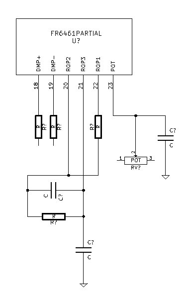
Magnifying light + continuity tester + pictures + dinner + lots of screw-ups eventually produced this schematic:
Seems fairly straightforward, I guess? In any case, it does seem to match the application circuit from the datasheet. Oh well, it was still a good exercise in reverse engineering.
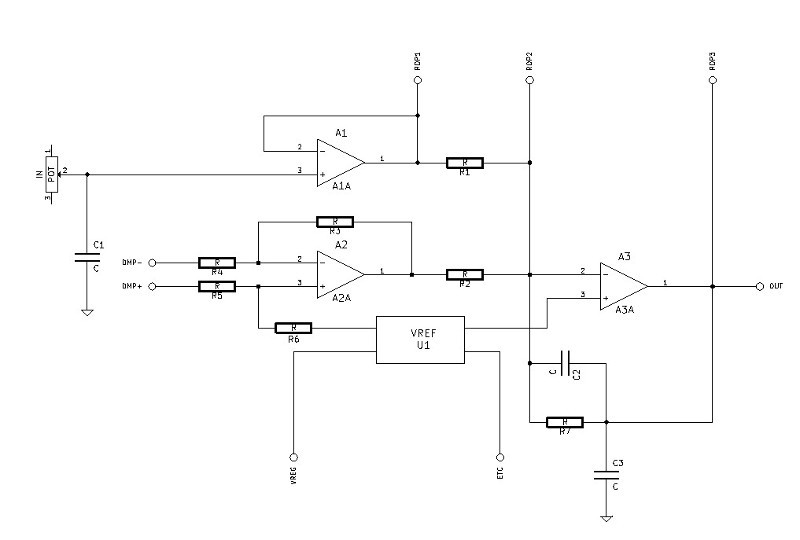
Next, I combined the physically derived schematic with the FR6461 block diagram:
Sorry it's a bit tough to see the component numbers; I dumped the Kicad file as a Postscript, used a website to convert that to a *.gif, saved that as a *.jpg, and cropped/scaled it a few times (given all that rubbish, I'd say it turned out pretty well!). You can ignore the reference connectors; they just indicate where the IC pins line up. In any case, I think I can now compare this circuit to one sketched by Bob Pease in 1995 (he calls it figure 1), reproduced below:
![]() Still a bit of a mystery, I guess. I'm trying to find the Derivative band section, but from what I can tell those are always coupled to the main input using a capacitor. The only op-amp that has a capacitor on its input is A3, and that capacitor (C2) loops around as a feedback circuit. I suppose R7 (below C2) could be RF in Bob's sketch and C2 is the added 0.1 uF cap; but where is Cin?
Still a bit of a mystery, I guess. I'm trying to find the Derivative band section, but from what I can tell those are always coupled to the main input using a capacitor. The only op-amp that has a capacitor on its input is A3, and that capacitor (C2) loops around as a feedback circuit. I suppose R7 (below C2) could be RF in Bob's sketch and C2 is the added 0.1 uF cap; but where is Cin? I'm not ready to look at the answer yet; it's a bit past midnight on a weeknight, so I'm going to sleep on this one and give it some more thought after work tomorrow. Any more hints, K.C. Lee?
-
Hackaservo.io, part 3
08/15/2014 at 01:18 • 0 commentsOkay, 45-minute-later update with two pictures, front and back of the board. I should put together a macro setup, that was too much of a pain. I'm going to copy these to the white board and start linking vias.
Chip side:
MOSFET side:
-
Hackaservo.io, part 2
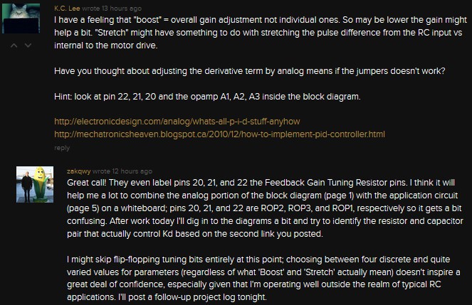
08/15/2014 at 00:29 • 0 commentsThis post can only start with a comment I received on the previous post from K.C. Lee. My response is also shown below:
It's an excellent comment from someone who wants to help me learn more about analog circuits. Unfortunately, K.C. Lee posted a previous comment that was a bit less Socratic; I saw the previous (and subsequently deleted) comment show up on my feed this morning. Full disclosure, people: I copied the answer into an email, sent it to myself, and haven't looked at it since. I want to explore this circuit on my own--I've never done much with op-amps--but it will be nice to check my answer when I'm done. I hope you trust that I've done that.
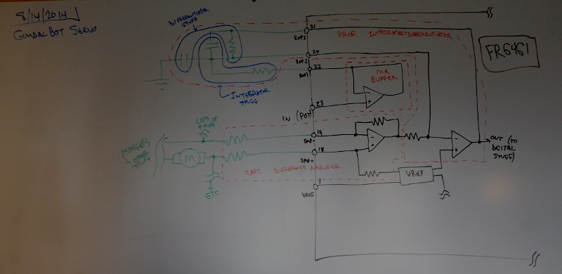
First, as I suggest in my comments above, I used my whiteboard to combine two items from the FR6461 datasheet: the chip's internal block diagram and the application circuit. I cut off a decent amount of circuitry from both sides, but I think I've captured the relevant stuff (apologies as always for the shoddy whiteboard picture quality):
A few things to highlight on the diagram:
- Black symbols and lines are from the internal FR6461 block diagram; green symbols and lines are from the application circuit.
- Like I said, I'm pretty new to op-amps; I've seen Dave's great intro video (amongst a few others on the same subject) and played around with 741s as audio preamps as a kid, but I've never gotten in to any sort of depth with the things. I read through a great report (*.pdf warning) I found online from UPRM, and tried to identify different op-amp circuits from the diagram. They are as follows:
- Mr. Buffer. He handles the incoming signal from the potentiometer, which returns an instantaneous measurement of the current servo shaft position, and presumably scales it to a value usable by the rest of the circuitry.
- Prof. Integrator-Differentiator. At least, that's what it looks like, based on the Integrator and Differentiator sections of the report linked above. I used blue marker to highlight the resistor and capacitor associated with each function.
- Capt. Differential Amplifier. His inputs are connected to quite a few items, but from what I can tell he's looking to see what the entire system is telling the servo to do; not where it is, but what direction it's going and how fast it's trying to get there. Presumably, looking at the differential across the motor drive circuitry will output a signal proportional to speed and direction, which is then fed in to Prof. Integrator-Differentiator. Here's the concern I have with this: why is the furthest-left capacitor grounded? Is it just a filtering cap to deal with noise? Do the Integrator and Differentiator functions actually share the second capacitor? That seems like it would make a bit more sense; in the second document K.E. Lee linked the second design (series PID algorithm) seems to follow the right side...
- Okay, back up for a second. I can't line up the circuit with any of the examples shown there; the resistor and capacitor staying in parallel doesn't seem to follow, given that they are connected to the output of the rightmost op-amp. I can only find op-amp sample circuits where the capacitor is used in series with a resistor in the feedback line, not parallel.
- Time to do a bit more reading.
- Okay, midway through some reading. It looks like the center capacitor--the one in parallel with the resistor--is there to prevent local amplifier oscillation. I'm marking that on my board. The resistor and capacitor I labeled are part of the differentiator circuit; still not clear on why the capacitor is grounded though. More reading!
So I'm still not entirely clear on how the circuit works, but I'd like to understand how the thing is actually wired. As such, I'm going to do two things; first, I'll draw a blown-up picture of the PCB; second, I'll try to derive the schematic for the above circuit from that drawing, and related it to the FR6461 block diagram (probably erasing the green stuff in the process); third, I'll redraw the entire thing as a flat schematic, pulling the resistors and capacitors into better positions with respect to the various op-amps. I keep getting confused looking at the board, since the FR6461 pin positions force me to change schematic wire routing.
Comments are welcome. I'm going to stop this log now but will hopefully post another tonight with an as-built schematic of the analog portion of the servo board, integrated with the FR6461 block diagram.
GimbalBot
Gimbaled thrusters, aerospace-grade adhesives, carbon-fiber-reinforced polymers, and inertial measurement units. This is a space project!
 zakqwy
 Still a bit of a mystery, I guess. I'm trying to find the Derivative band section, but from what I can tell those are always coupled to the main input using a capacitor. The only op-amp that has a capacitor on its input is A3, and that capacitor (C2) loops around as a feedback circuit. I suppose R7 (below C2) could be RF in Bob's sketch and C2 is the added 0.1 uF cap; but where is Cin?