The other day I stumbled on a couple videos from by @Jesse Schoch , wherein he actually implemented anaQuad in a system, gave a pretty thorough overview/discussion, and even expanded on it both in software and by using it in a unique way!
My work was Peer Reviewed!
like... the highest honor for a scientist... and somehow I didn't find out, except by accident, two years later. Believe me, Jesse, I'd've definitely been in contact, had I known.
ON TO THE VIDS:
Jesse doesn't have much of a profile here at HaD, instead he has a wealth of YouTube videos of such projects and concepts.
Back in 2019 (I almost wrote 1999, jeeze I'm old), Jesse dedicated some of his time to implementing anaQuad, and made these vids.
(Apologies; I'd planned to be more thorough in analyzing the vids, themselves, but these days I'm on flakeynet most of the time... I cross my fingers every time I click "Save". Heh!)
Part 1:
Jesse discusses a use-case I'd never considered, a pair of analog hall-effect sensors used to detect the 2mm-spaced alternating poles of a magnetic strip (refrigerator magnet) passing by. AnaQuad is used here to determine the linear motion/position.
I'm not sure I understand his sensor, it has an X and a Z axis, and somehow their readings are at or near 90deg out of phase. However it works, it's a great observation, and a perfect use for anaQuad!
It reminds me of a linear version of 5.25in floppy spindle motors, which have a similar magnet with many alternating poles wrapped around the edge of the (for lack of a better word) flywheel. The hall-effect sensors, there, are three-phase, so offset by 60deg each. I did once modify anaQuad[120] for two of those sensors. Though, the poles were so far apart that resolution was quite low despite the 10+ inches of magnet spinning by.
One observation about this setup is that, if I understand hall-sensors, the waveform output by the sensors would vary in amplitude (and DC-offset?) if these magnets aren't perfectly-aligned with the sensor throughout the entirety of their motion. E.G. if the sensor's path relative to the linear strip isn't /perfectly/ parallel. Also, who knows about the magnetic poles themselves? Surely a fridge-magnet isn't made to tight tolerances. Here, I'm not so much talking about the spacing, that's probably pretty consistent due to the machine that made it. Instead I'm talking about the /strength/ of each pole being consistent across the entire strip. E.G. I would imagine some poles may weaken with various outside factors; being exposed to other magnets on the fridge, etc. Or, also, plausibly, if this is used on an axis of a metal-cutting CNC, the measured flux may vary slightly based on the amount of nearby metal stock.
THIS IS A PERFECT USE FOR anaQuad.
The whole point of its crossover-detection is to reduce the effects of such things on the position-sensing. Imagine one weak pole surrounded by many normal ones, for which the system was calibrated. There, the sine-wave would have a reduced amplitude. And, the surrounding poles might even cause it to have a slight offset from "zero". I won't go into all the details, they've been harped-on in other logs, sufficed to say anaQuad is by-design highly tolerant to such variances.
...
In this first vid, Jesse touches on the concept of merging anaQuad with "sin-cos" postioning. This, honestly, is something I never really considered, as I'd kinda figured the two to be somewhat competitors. Heh!
Part 2:
In the second video, Jesse goes into a bit more detail about how anaQuad works, then shows how to combine it with trigonometry to gain even higher positional-resolution.
The use of trigonometry is something I was /actively/ trying to avoid when developing anaQuad. So, it's difficult for me not to go into all the details of why, and instead see the benefits. I'll try to be open-minded ;)
First-off, having seen his graphical visuals, then inspired to run my own calculations, I'm actually quite surprised at how tolerant the use of arctan is to things like DC-offset or amplitude differences. I was imagining a tiny measurement error would cause a huge positional error, and actually that's not particularly true. [Except in a few places, which can be avoided by a simple trick, I'll describe later].
So, after I stopped cringing about trig being compared to anaQuad, I learned something, heh!
I gather that the key concept is that trig can only be used to determine a position within one "step"/cycle... (in fact, only within one half of a cycle!). so... /something/ has to track how many magnetic poles have passed the sensor, and which half of the cycle it's in.
Jesse chose to use anaQuad for this purpose, and I... well... never thought of it like that. A "coarse position and direction tracker". Heh, I was quite proud of how /fine/ I'd gotten its positioning resolution! 16 positions from one slot in an encoder disk!
But, he's spot-on. It /is/ coarse, compared to what /could/ be determined by two sine-waves 90 degrees out of phase. Heck, that's kinda the whole point of trigonometry... sine and cosine make a circle, not an octagon.
So, trig still uses a lot of very slow computations (in floating-point, no less!), in comparison to anaQuad, which uses, as I recall, raw integer measurements from the ADC, a quick jump-table followed by four additions and four comparisons. My guess is that anaQuad should be hundreds of times faster than trig, even on machines with FPUs.
But, again, it's apples and oranges, since trig alone can't keep track of /how many/ cycles, which half-cycle, nor which direction. And, likewise, anaQuad can't even begin to approach trig's resolution.
So, where does this leave us? If resolution is not /highly/ important, anaQuad does a way better job than digital quadrature (I'd better rename anaQuad anaQuadrature, as it's near impossible to search). It's also, similar to digital quadrature, highly immune to external factors. But if you need resolution, trig is the way to go.
Now, some caveats. BOTH are still prone to inaccuracy. And, my guess is, roughly the same amount. Just because anaQuadrature (QuadrAnalogature? AnaloQuad? CrossoverQuadrature?) can detect 16 subpositions within a cycle does /not/ necessarily mean each of those is 1/16th of a cycle apart. In fact, in order to make it fast, some are /definitely/ NOT perfectly evenly-spaced. But that's rather irrelevant, because, again, the fact is these two systems are very much analog, and very much susceptible to many factors.
The fact is, so are /digital/ optical encoders, but it's much harder to see that. In the motion of one slot's passing the sensors, the outputs are in one of four states, so it's easy to imagine that those four states are exactly 1/4 of a slot. But, that's not necessarily true. The brightness of the LED(s?), the sensitivity of the phototransistors, the calibration of their biasing, the thresholds/hysteresis of the Schmitt-trigger/comparator inputs, the tolerance in the sensors' 90degree alignment... all these factors can cause quite a bit of variance in sub-cycle positioning-accuracy.
(I highly recommend looking at the tremendous amount of circuitry used in early Digital Optical Quadrature Encoders from HP... (e.g. from the 7475A plotter. TODO: upload a photo?) they could've simply used a phototransistor, a resistor, and a schmitt trigger for each channel. It's just looking for on and off, rrrriiiggghhhttt? They didn't. Precision and accuracy are very different things! Props to the skill that went into those!)
And I haven't even mentioned external factors like thermal-effects on circuit-components, electrical/RF/60Hz interference, dust, light-seeping...
So, realistically, with any of these systems, pretty much the best accuracy one can /guarantee/ is about +-1/2 of a "slot", as I see it.
Now, obviously, that doesn't mean the subposition information is useless. It just means that one must be conscientious about what the numbers actually mean, and how they can be used. ("Not for life support systems!")
E.G. I don't know if I'd think it wise to use such subposition measurements, even from a digital encoder, to cut threads on a tiny screw. (Nor, and far worse, microsteps of a stepper motor!). But, if I was making a "jog-dial" with high precision at low rotation-speeds and fast-scrolling at higher speeds, trig+anaQuad, may be just the ticket. Frankly, I'm blanking on uses, at the moment, but therein lies another thought...
anaQuad is great for fast-motion... So, e.g. trig may just not be used during such motions, but as the "ticks" start to slow (decelerating near an endpoint), there'd be more processing-time between ticks, which could then be applied to sin-cos for the fine endpoint positioning. Hmmm...
...
Another thought is about Jesse's "jumps" in the measurements. Arctan, as I recall, outputs from -90deg to 90deg, then jumps back to -90 and repeats.
anaQuad, then, is used to determine /which/ -90 to 90 "hemisphere" the sensors are detecting. Then, the two sensor readings are fed into arctan to get an angle (from -90 to 90deg, which corresponds to /subposition/) within the waveform, i.e. between two opposite magnetic poles.
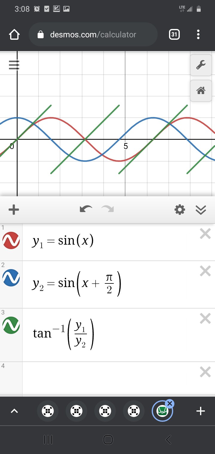
Again, /near/ those +90 to -90deg jumps, it's /very/ sensitive to measurement error.
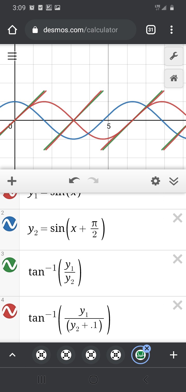
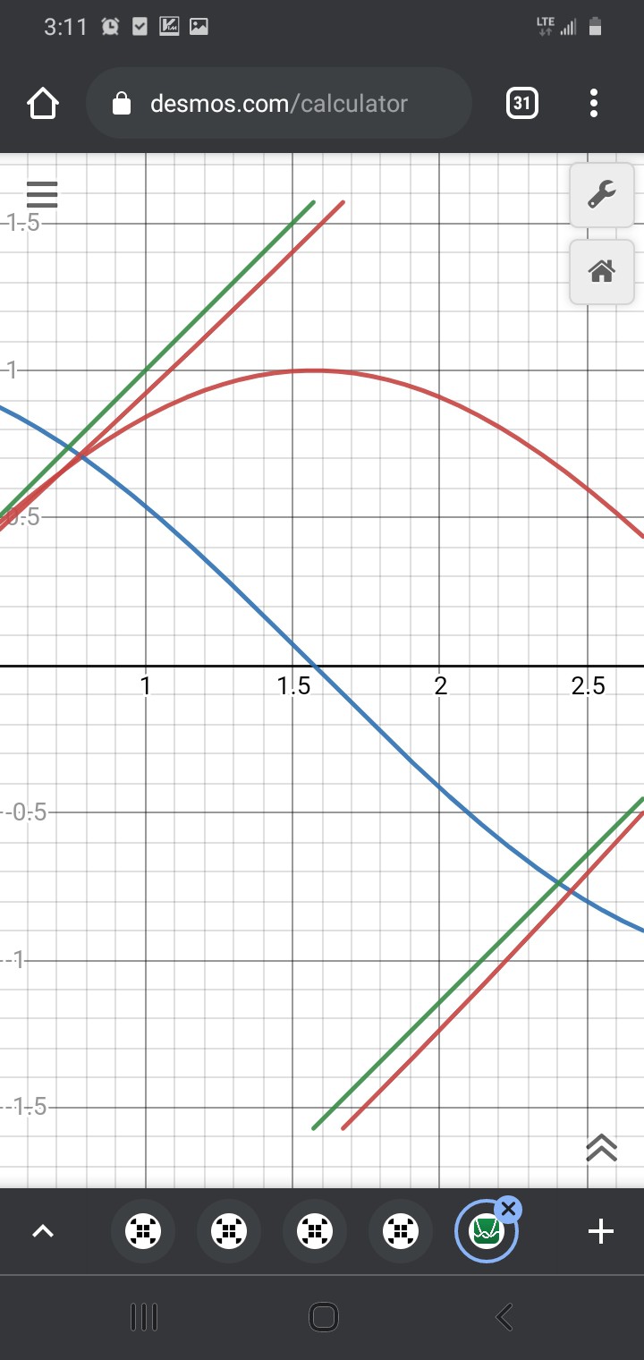
You see, even though the arctan method is, for the most part, /surprisingly/ accurate, despite the 0.1 measurement-error, that tiny measurement error can become a /tremendous/ error near arctan's "jump."
Near the jump, using arctan to calculate the subposition, it may be off by as much as a full 180deg! And, yet, again maybe only /very/ briefly, e.g. if this was detected during a CNC axis motion. If this positioning system was used in a feedback loop to *control* the motion, the effect could be quite gnarly (Keep fingers away from moving parts! Always have a big red E-Stop button that actually cuts power to the motor!)
The likelihood of encountering this error may actually be exasperated by the use of anaQuad... but will be a problem in any such system forgetting to take into account special handling of that case.
anaQuad may be able to tell you it's to the left of the jump, but its position-measurement-system definitely differs from the scaling and offset calibration used for the trig calculations. It works based on crossovers between the signals themselves, not measured /values/ relative to the ADCs' ground... so really the two systems are working in two different playing-fields. And, again, I chose that different playing-field for anaQuad /by design/ for the sole purpose of avoiding the ambiguities caused by measurement error. It's similar in concept to differential-signalling, which is often used for noise-immunity.
But, that doesn't mean those two "playing fields" don't overlap... they may be slightly shifted, slightly stretched or shrunk relative to each other within each fraction of a cycle, but they *do* overlap.
...
So, here's the "trick" mentioned earlier....
Make use of anaQuad's multitudes of subpositions.
Then, Trig's playing-field can be subdivided such that there are no discontinuities...
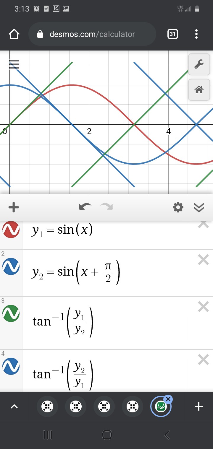
Wait, what? SOH CAH TOA says tan=opposite/adjacent, and sin<->opposite while cos<->adjacent... it's not soh cah TAO!
But does it really matter, here? The fact is, we have two straight lines which cross each other, then it's only a tiny bit of math to align them:
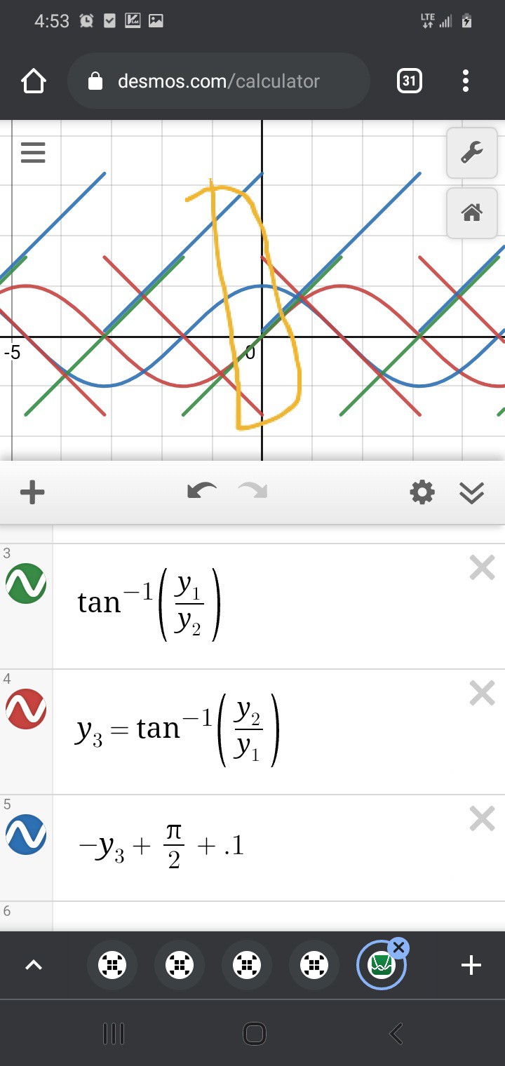
(I added 0.1 so the overlap of arctan(y1/y2) and the extension from -arctan(y2/y1)+pi/2 would be more visible)
Thus, there is plenty of overlap where /either/ subposition-calculation should determine the same subposition, and it no longer matters how precisely-aligned anaQuad's and Trig's "playing-fields".
Will the results be identical? No. Will there be no "jump?" It might jump a tiny bit when switching between calculations, but it shouldn't introduce gigantic blips of error. I dunno, I've never done it before, you try it!
As I see it, as long as you stay away from eithers' discontinuities, it should be at least as accurate as could've been guaranteed otherwise.
(Upon further thought, it's entirely feasible that upon switching calculation methods, the detected position might *backtrack*, briefly... These are the woes of analog. Again, it might not be wise to feed this into a PID algorithm controlling the speed of a huge motor!)
...
Anyhow, Thank You to Jesse. Seriously, I consider your efforts like Peer Review of my months of scientific research.
(HEY HaD, WOULD YOU PLEASE fix the email notification system?! This is not even remotely the first time I stumbled on comments I never received notification of. So... what...? he clicked "follow", then wrote a comment, in the same hour, and you think I care more about a skull than a comment?! Or you expect me to run a 'diff -r' on all my projects/logs/etc, every day?! I would if it were that easy...)
Sorry, folk, this is a years long beef, that was absolutely necessary.
 Eric Hertz
Discussions
Become a Hackaday.io Member
Create an account to leave a comment. Already have an account? Log In.
" Near the jump, using arctan to calculate the subposition, it may be off by as much as a full 180deg! "
So this isn't actually a problem. I implemented a fully "trig" DRO in my video "$7 fridge magnet dro using 3 phase signal from TMR sensors", not sure if you watched that one... The thing that works here is that inverse tangent (arctan) has a special form called "four quadrant inverse tangent" or atan2. This does some anaquad like tests to figure out which "phase" you are in and constrains the result to the range
-pi..pi. The regular atan just creates a repeating sloped line of length 2pi that repeats forever. Because atan2 is constrained you don't get off by a huge amount but there is some hysteresis around the boundaries where
things may ocellate however that doesn't have a huge impact on your readings.
The more recent 3 phase setup uses very sensitive TMR sensors and creates a virtual sin/cos signal which has some inherent error correction. I found the method in on of the many papers I read on this topic. I can dig it up if
you want.
Are you sure? yes | no
Ah, thank you, I see it here:
https://youtu.be/yj12mNjl5RE
Hadn't thought about it before, but I can imagine having three-phase measurements, even if mathed-down to two, could actually do quite a bit for immunity to noise, amplitude variations, etc. Actually, that might just be the missing-link anaQuad[120] needed, toward making it even more noise tolerant, and thus allowing for another iteration of resolution-enhancement.... (the most-questionable "crossover" is sine with -sine, since they're from the same single signal and since the DC offset has to be accounted-for, but is technically unknowable, in both. That error multiplies. Heh! A third phase could mean that /every/ crossover-detection occurs between two separate sensors, thus their DC-offsets cancel, like "differential-signalling" or a balanced-microphone) Hmmmmm...!!!
You mention anaQuad again in this video, Wow! I really had no idea anyone even noticed it, nevermind actually remembered it two years later, fondly nor otherwise... heh.
I do think you're right, though... it was never really intended for an overall endgoal like yours... Apologies for sending you down the wrong rabbithole.
I've a draft log "Do you need anaQuad?" To which the simple answer is: "probably not, its intended niche is... well... very niche."
Though, it is great to see its being used!
My guess is atan2 takes two arguments, instead of one, which allows for signs on both numbers, which then makes it possible for it to determine the quadrant... at which point, indeed, there's no need to use another system to determine the quadrant! (Though, the same could've been achieved by looking at the signs before feeding the fraction to arctan... so... yeah... anaQuad was a bit of an unnecessary rabbit hole, there, too. Oof!)...
But, I'm not sure what to think about even atan2's discontinuity... i think the "noise" results in my next log would apply still. But, if you're only using this system as a DRO (as opposed to feeding those measurements to a motor-controller), the odds of you actually encountering oddness due to such a discontinuity is very very slim!
One more thought, it seems we have different definitions of hysteresis... in my experience, it's something one chooses to implement for the sake of reducing sensitivity to noise. You seem repeatedly to use it to describe something different, something to account for errors?
Ah, and still one more thought: it is entirely plausible your new system would be highly accurate to 2mm increments but somewhat repeatably stretch and shrink between those increments, due, for instance, to the shape of the flux-density (maybe the sensor detects more of a sawtooth wave instead of sinusoidal). Something like that could be compensated-for with a tiny bit of math after the fact, if necessary, so keep your eyes peeled for a repeatable error like that!
I think I can pass on the links to the trig papers. I don't foresee myself needing such precision in my endeavors. Though, I suppose they may be useful to others in the "Do you need anaQuad?"...
Do you mind if I ask how you came across aQ in the first place? Do you know others who have used it? Maybe I can address that so others know what they're getting themselves into (or know not to).
Are you sure? yes | no