 Grant Giesbrecht
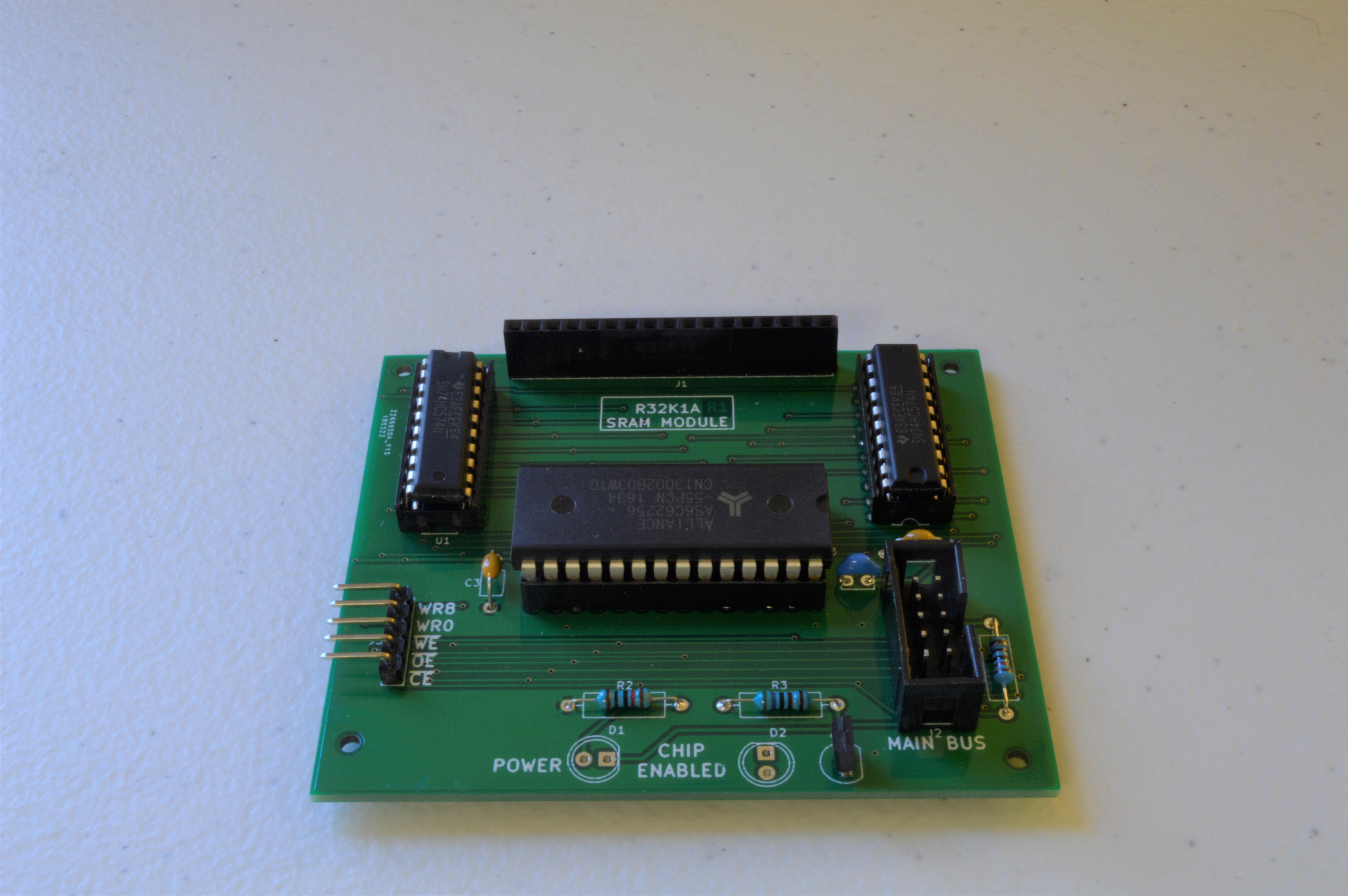
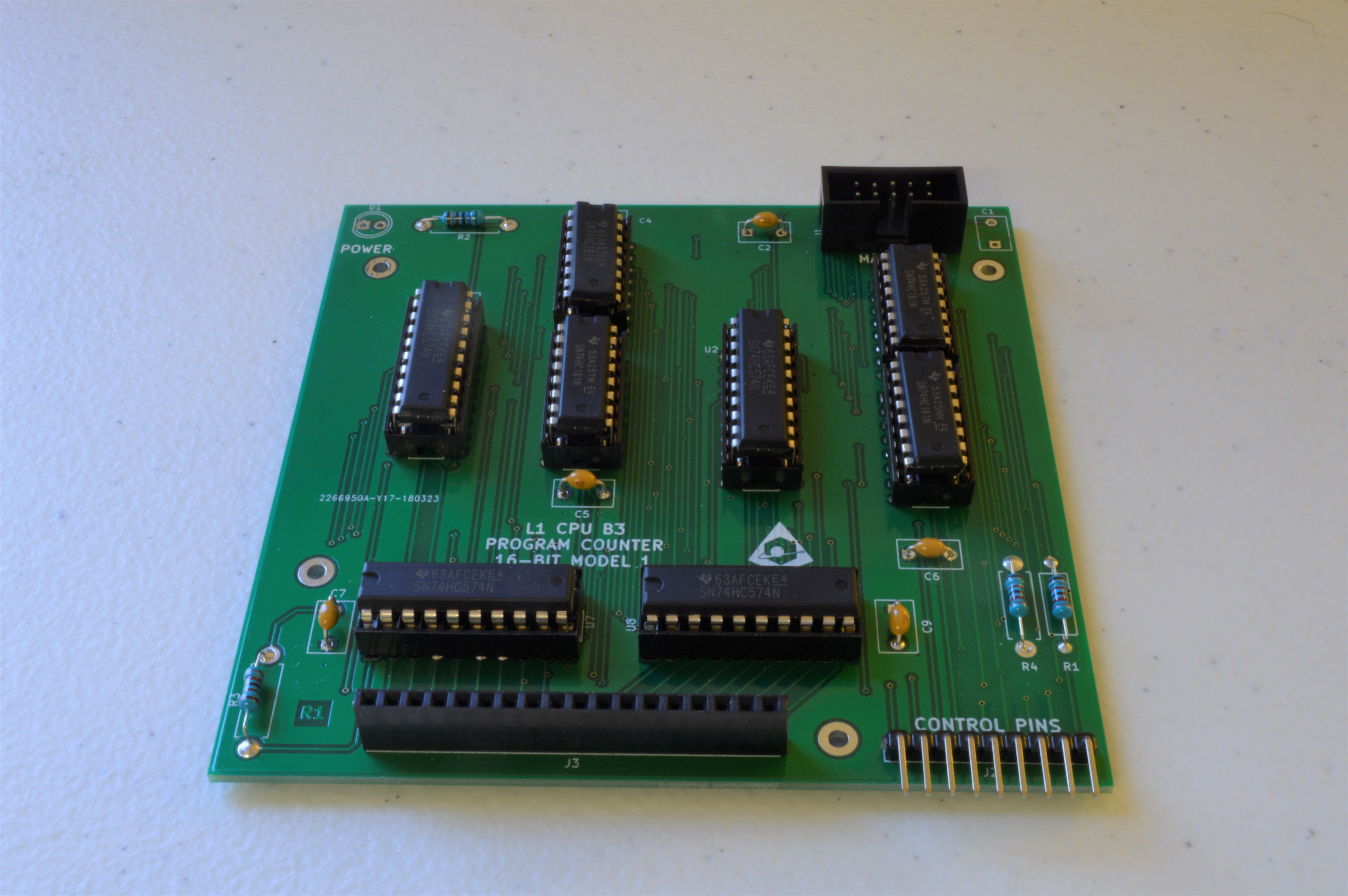
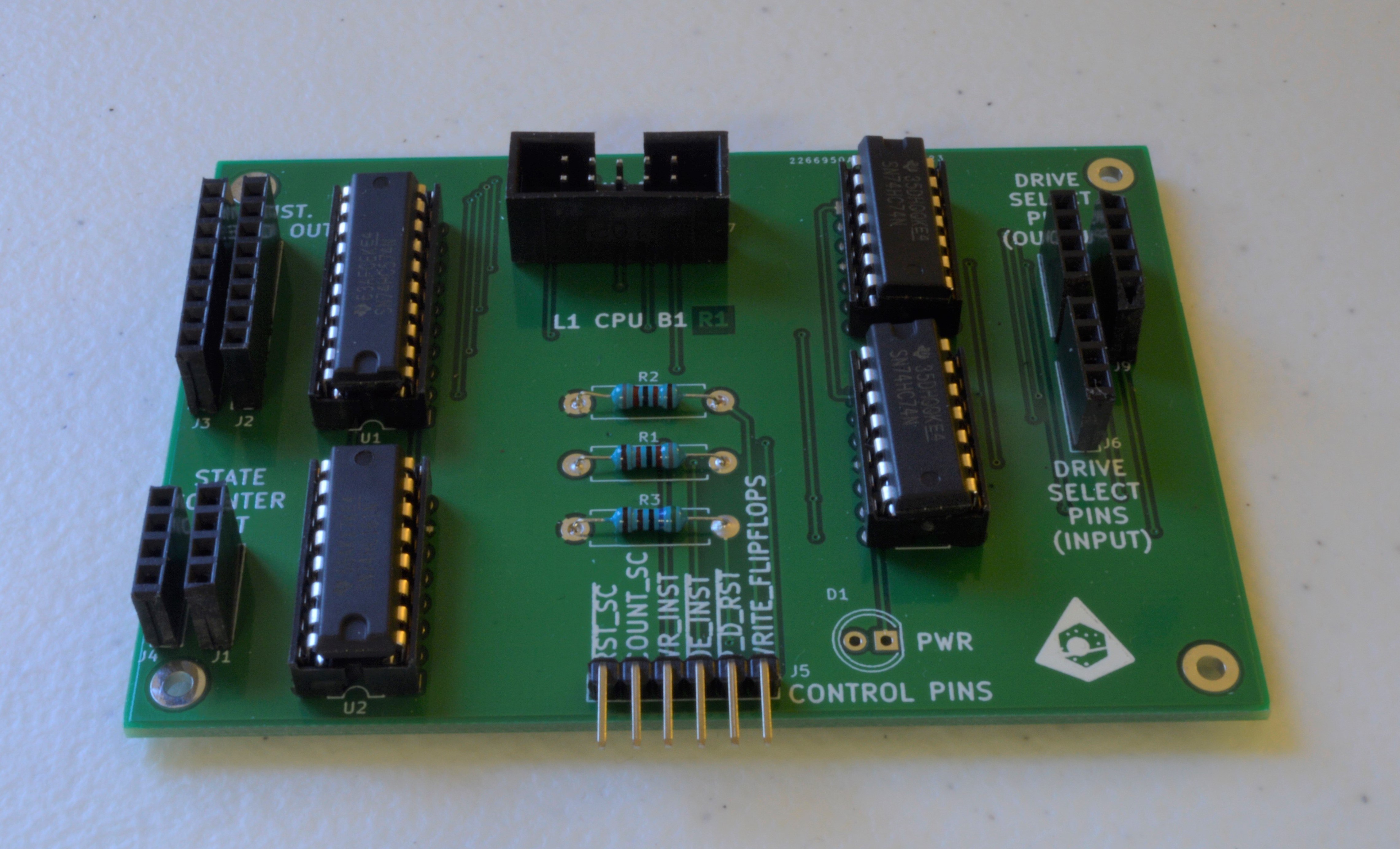
I got my PCBs in the mail and assembled them. This batch included the boards for my RAM module, 2 boards for my CPU, along with the remainder of the boards for the ALU. I can't test the ALU yet because I need to order more chips to finish populating the boards. The RAM board works (except for Q1, whose source and drain I swapped in the schematic. It's a simple enough fix, however; you've just got to flip the transistor around 180 degrees), along with CPU board 1 (houses instruction register, flip flops to specify which flash memory device from which to read the program, and the state counter). Alas, CPU board 3 (program counter) needs to be remade - I made a wiring mistake in the schematic.
Discussions
Become a Hackaday.io Member
Create an account to leave a comment. Already have an account? Log In.
nice looking design! look forward to seeing more posts!
Are you sure? yes | no