 Lutetium
 you need to have a good resistor and a good op amp
and there are a broad range of parts you can buy
 ...and a bypass cap across Rf.
so understanding the critical things will allow you to buy better components that allow more accurate readings
any questions about that circuit?
in the case of that circuit, the resistor is super critical
if you imagine you have a resistor that is a different value than you think it is (say 1.2M instead of 1M), you can calibrate for it
 In the event you would want to measure the current through the photodiode with a scope, are you looking at a 1% tolerance resistor or better?
but say you have a resistor that isn't perfectly linear
then you can't really calibrate for that
![]() @Chris Gammell last question from me: In your experience, how much does good/bad PCB design/layout contribute to the performance of the circuits we are talking about, qualitatively speaking of course.
@Chris Gammell last question from me: In your experience, how much does good/bad PCB design/layout contribute to the performance of the circuits we are talking about, qualitatively speaking of course.
> In the event you would want to measure the current through the photodiode with a scope, are you looking at a 1% tolerance resistor or better?
So you wouldn't be able to measure that current directly, a scope measures voltage
 Can you just use any high gain opamp? Is it critical?
but that circuit actually is a current-to-voltage converter
 @Dustin Sackett you can solve a lot of analog problems with the right capacitors between power and ground, as well as a very large ground plane.
I meant a series resistor you place in for test purposes only.
so if you have a good resistor, you can say with confidence that you're looking at what the current is, represented by the voltage output from the op amp
> Can you just use any high gain opamp? Is it critical?
No, the other specs matter quite a bit
if you have a high offset voltage between the inputs, that can impact things
the input bias current will have a large impact in this case as well
> In your experience, how much does good/bad PCB design/layout contribute to the performance of the circuits we are talking about, qualitatively speaking of course.
Using that example above again, it can be quite a bit
if you have a poorly laid out circuit, it can really impact analog things
much more than say an i2c bus
but I'd say if you're in the microvolt range or below, then it'll be a bigger concern
as a general rule
similarly if you're in the nA of current measurement range, it'll have a big impact
but that also extends to cleanliness of the board as well
In my experience, if I can make an analog circuit robust enough in a breadboard, then getting it to work on a PCB is relatively easy.
any leakage path in an analog circuit is a potential place your circuit accuracy can get worse
> In my experience, if I can make an analog circuit robust enough in a breadboard, then getting it to work on a PCB is relatively easy.
Yeah, agree with that
there are definitely spots where a breadboard will start to breakdown
usually 10MHz+ on the frequency side of things
Yes, parasitic capacitance
and those same values above for voltage, current
![]() Is that somewhat frequency dependent, both for the the analog signal of interest, and the related digital signals (SPI, I2C, etc)? If so, do you have a threshold for where things become trickier?
Is that somewhat frequency dependent, both for the the analog signal of interest, and the related digital signals (SPI, I2C, etc)? If so, do you have a threshold for where things become trickier?
![]() ^^ I see your 10MHz comment now!
^^ I see your 10MHz comment now!
> Is that somewhat frequency dependent, both for the the analog signal of interest, and the related digital signals (SPI, I2C, etc)? If so, do you have a threshold for where things become trickier?
For most things I was working on (and still work on when doing low level meausrement), it's a slow measurement
High-speed stuff is a whole other world. I work in the audible range. Much easier.
if you get a DMM off a shelf
and go to measure low level signals
say a 5.5 digit DMM
if you're looking at the bottom of that range, uV measurements
you're normally integrating measurements over a long period to get more accuracy
so usually on the 1s scale
depending on how fast you like seeing your digits dance around the screen
what are you using for the integration over time?
> what are you using for the integration over time?
In the DMM?
that's built in, there are analog to digital converters that are averaging measurements
https://en.wikipedia.org/wiki/Delta-sigma_modulation
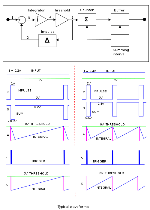
Delta-sigma modulation - Wikipedia
Delta-sigma ( ΔΣ; or sigma-delta, ΣΔ) modulation is a method for encoding analog signals into digital signals as found in an analog-to-digital converter (ADC). It is also used to convert high bit-count, low-frequency digital signals into lower bit-count, higher-frequency digital signals as part of the process to convert digital signals into analog as part of a digital-to-analog converter (DAC).
Well, I would prefer to know how you would tease out a tiny signal from a noisy world using only discrete components.
that's a standard method for ADCs
passive discretes? Like Rs and Cs?
Yes. And transistors, diodes are fine too. Just discrete component -- no chips
It explains the principle better
Like stages of filters
transistors and diodes are active, so that's what I wnated to deliniate
putting power into a system to help amplify is an important distinction
short answer for 2019: I wouldn't
discrete components are fun, but there are so many better tools out there
if I was going to study to go and design chips for the industry, I'd be doing more transistor level design
Understood, but it's hard to grasp what the "other tools" are doing inside of that black box.
I see!
yeah, it's frustrating sometimes
and understanding the underlying architectures can help
understanding what's happening at the input to an op amp, for instance
That's the benefit of discrete component examples (active, passive, makes no difference -- just out in the open. Not black box)
there are diodes in there which can mess up your measurements sometimes
How so?
as you get closer to the rails, it's possible to get "stuck"
Due to the voltage drop?
Excellent points Chris! (ADC, sampling, PCB layout, measurement repeatability/accuracy)!!!
so if you have an op amp with +/-15V rails, I normally would try and keep the incoming signals between +/-10V
this has gotten better on modern parts
but old parts, this was a big issue
Stay away from the rails = "Mind the gap" LOL
haha
yeah
So rule of thumb -- give your parts 30% more power than your signal?
so if I went and built up an op amp from transistors (possible), I'd have to deal with a lot of the issues that op amp designers have dealt with for years (and improved)
> So rule of thumb -- give your parts 30% more power than your signal?
No, I wouldn't say that. It's more "read the datasheet"
and find parts that optimize your signal chain
Of course
![]() "Read the datasheet"
"Read the datasheet"
We need t-shirts
yeah, kind of like the RTFM stickers from Sparkfun
Are a lot of people in here using analog signal processing in their projects?
@Chris Gammell Thanks for getting into the weeds. You can return to fancy expensive equipment
would love to get a sampling of what people are currently doing
or looking to do
 > so if you have an op amp with +/-15V rails, I normally would try and keep the incoming signals between +/-10V
Rail to rail or bust. Who cares about money? :)
also, let's hear it for the Hackaday crew in the house! Thanks @Mike Szczys and @Dan Maloney!
thanks!
Would you recommend the art of electronics to learn more about analog circuit design?
 On the tips and tricks front. What sort of DFM tricks do you roll into your analog designs? Any sort of calibration at manufacture time concerns, for example?
 @Dan Maloney does an excellent job with the Hack Chats, nice work! And thanks to @Chris Gammell and a million others for hosting!
FWIW my utility for "low level" design is more in characterization of more commonplace designs, without having to buy a $32342342311 SMU or power analyzer.
Chris, I'm working on a "precision rectifier" circuit also known as a "super diode". A diode and op amp (to be sampled by an ADC).
When I think "low level measurement" I think more "CurrentRanger" and less analog design.
> Would you recommend the art of electronics to learn more about analog circuit design?
Depends on your goals. AoE is a good overview, but ther are lots of good books out there. Jim Williams app notes are free
or you can read the "Analog Circuit Design" books from Newnes
which are just compiled versions of those things
 I'm working on a DIY CO detector using a sensor like this:
https://www.sparkfun.com/products/9403
> On the tips and tricks front. What sort of DFM tricks do you roll into your analog designs? Any sort of calibration at manufacture time concerns, for example?
As Mike Harrison said on Embedded.fm this week, "You can never have too many test points"
I'm actually going through your 'Getting to Blinky 4.0' playlist now so I can design it in KiCAD.
killer episode, btw: https://embedded.fm/episodes/294
As for other calibration things, the best tip is to not need it
so if you can pay that extra dollar for a high accuracy resistor, pay for it
calibration is expensive
and it sucks
so balance it with the overall cost of the product
aside from that, hire great manufacturing engineers like @monk :-D
"I need more test points" another great shirt idea -- perfect for FW and Manufacturing engineerings ;)
Discussions
Become a Hackaday.io Member
Create an account to leave a comment. Already have an account? Log In.