Close
0%
0%

High-Speed PCB Design with Bil Herd

Square traces? No problem! Probably

Wednesday, September 25, 2019 12:00 pm PDT Local time zone:
Hack Chat
Similar projects worth following

Bil Herd joins us for the Hack Chat on Wednesday, September 25, 2019 at noon PDT.

Time zones got you down? Here's a handy time converter!

Join Hack ChatPrinted circuits have become so commoditized that we seldom think much about design details. EDA software makes it easy to forget about the subtleties and nuances that make themselves painfully obvious once your design comes back from the fab and doesn't work quite the way you thought it would. 

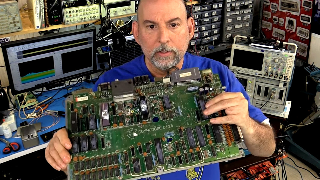
PCB design only gets more difficult the faster your circuit needs to go, and that's where a depth of practical design experience can come in handy. Bil Herd, the legendary design engineer who worked on the Commodore C128 and Plus4/264 computers and many designs since then, knows a thing or two in this space, and he's going to stop by the Hack Chat to talk about it. This is your chance to pick the brain of someone with a wealth of real-world experience in high-speed PCB design. Come along to find out what kind of design mistakes are waiting to make your day miserable, and which ones can be safely ignored. Spoiler alert: square corners probably don't matter.

  • Hack Chat Transcript, Part 3

    Lutetium09/25/2019 at 20:58 0 comments


    Bil Herd1:04 PM
    I will be talking about PCB fab in the next viddeo. I will try and work in some of these questions into that

    Bil Herd1:04 PM
    Thanks everyone!

    Nicolas Tremblay left  the room.1:04 PM

    Bil Herd1:04 PM
    @frank Give me an hour with ya and I could have ya doing Gig stuff!

    Frank Buss1:05 PM
    I'm just a programmer, tinkering a bit with hardware :-)

    Paul Stoffregen1:05 PM
    Didn't wanna interrupt earlier with an off-topic question... but hopefully ok now to ask if anyone's done a PCB design using 0.4 mm pitch BGA? I'm considering one soon (a 36 pin BGA). Any tips?

    Bil Herd1:05 PM
    Just to add, the stuff we did on 2 sided boards in the 80's was just awful, I would use 40-80 series resistors in a design

    Bil Herd1:06 PM
    @Paul Stoffregen Are you doing it yourself? What CAD package?

    Paul Stoffregen1:07 PM
    Yup. I'm a bit embarrassed to admit it, but I use an ancient version of PADS. It still works pretty well for me.

    Bil Herd1:07 PM
    @Frank Buss you know this stuff. You were asking the right questions in that other forum on FB. ;)

    Ben Jordan1:07 PM
    @Paul Stoffregen 0.4mm pitch - you will have to use Via-In-Pad HDI

    Bil Herd1:08 PM
    PADs is one of the progenitors of the industry.

    Ben Jordan1:08 PM
    I have a reference design I can send you with a freescale I.MX8 CPU if you like?

    Paul Stoffregen1:08 PM
    I guess that means I need to learn how to buy a PCB with via-in-pad... never done that befer

    Paul Stoffregen1:08 PM
    *before

    Bil Herd1:08 PM
    @Ben Jordan I would love a copy if you could email me at bilherd@hackaday dot com

    Ben Jordan1:09 PM
    will do

    Chris Hamilton1:09 PM
    @Paul Stoffregen you might be able to use thin traces which is slightly cheaper.

    Adam Oakley1:09 PM
    I've never had a manufacturer complain about via-in-pad, and I don't take any special steps to warn them or anything


    https://hackaday.io/event/167712-high-speed-pcb-design-with-bil-herd/log/169237-hack-chat-transcript-part-1

    HACKADAY

    Hack Chat Transcript, Part 1 | Details | Hackaday.io

    Well, we've been having some good sidebar discussion here for a bit, but let's kick it off officially and welcome Bil Herd to the Hack Chat. Today we're going to learn about high-speed PCB design. Bil, I usually ask hosts to introduce themselves to get things going, but that seems silly here.

    Read this on Hackaday

    Paul Stoffregen1:09 PM
    so you give them more than one drill file?

    Ben Jordan1:10 PM
    generally they know how to do it these days...

    Bil Herd1:10 PM
    I know someone that is as dedicated to PCB layout as I am to hardware. I run questions like .4mm by him in the form of "yes buyt what works in production?"

    Adam Oakley1:10 PM
    no, are you referring to via-in-pad with filling or something?

    Ben Jordan1:10 PM
    yes different drill files for each drill layer pair will be needed

    Bil Herd1:10 PM
    We were talking earlier about via in pad and sealing them and hot gasses

    Ben Jordan1:11 PM
    yeah if it's hdi, fabs will often plate them up to solid copper - no outgassing problems there

    Ben Jordan1:11 PM
    ballpark figures may be obtained by US based fabs

    Bil Herd1:11 PM
    I just read "The Designer's HANDBOOK for DFM" by Sierra Circuits, (DFM is design for manufacturing), I recommend it

    Ben Jordan1:12 PM
    was going to mentione Sierra!

    Frank Buss1:12 PM
    @Bil Herd do you mean this?

    https://www.facebook.com/groups/CommanderX16/permalink/524160045001761/?comment_id=524251758325923&reply_comment_id=524333631651069

    I think they will get into trouble, when they try to access the YM2151 with an 8 MHz clocked X16, it just works by chance now. But at least they can switch it to 4 MHz, but I think a latch to make the signal and data longer would be better.

    Bil Herd1:12 PM
    I am looking for the link, a good read for 80 pages... of course I printed it...

    Read more »

  • Hack Chat Transcript, Part 2

    Lutetium09/25/2019 at 20:07 0 comments

    Bil Herd12:36 PM
    Well crap that didnt work

    Bil Herd12:36 PM

    I blame Google

    Bil Herd12:37 PM

    Bil Herd12:38 PM
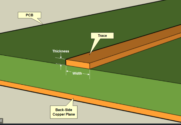
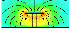
    So these images show a trace above a ground plane and the field around it.

    Nicolas Tremblay12:38 PM
    Got it, thanks

    Dave Blundell12:38 PM
    strawberry fields forever?

    Bil Herd12:38 PM
    So when we DONT match the impedance a reflection occurs. Truth be told we live with tehse reflections all over the place but...

    Bil Herd12:39 PM
    Enter the series resistor, I used to put 22 Ohm resistors in series to absorb the signal that got away from me and is bouncing up and down the trace

    Dave Blundell12:41 PM
    are termination resistors fitting into this picture too or no?

    Bil Herd12:41 PM
    A reflection occurs when the receiver doesn't absorb 100% of the signal

    Bil Herd12:41 PM
    if the transmitter is 50Ohms and the receiver is 55 ohms than a percentage will be reflected.

    Bil Herd12:42 PM
    If the transmitter doesn't absorb it it will be reflected again

    Bil Herd12:43 PM
    Is that kinda clear or should I talk more about absobing the reflection when they ARENT matched?

    Bil Herd12:43 PM
    By the way, my CAD package calculates the trace width for me

    Dave Blundell12:43 PM
    which?

    Dave Blundell12:43 PM
    (CAD package)

    Bil Herd12:44 PM
    Altium, Labcenter

    Bil Herd12:44 PM
    Eagle might, Ted you still there?

    Bil Herd12:44 PM
    Labcenter makes Proteus. Kicad also will with the right addon

    MatYay12:45 PM
    So from my understanding by adding a serial R on the tx side we allow the signal to reflect from unmatched receiver and to be absorbed at the receiver side. And that does not influence the reception quality because the receiver does not "see" the reflection caused by itself?

    Bil Herd12:45 PM
    Yes. AND its not radiated as much and it doesn't keep bouncing around creating noise, including FCC emmision noise

    MatYay12:46 PM
    right

    Dave Blundell12:46 PM
    I think using firehose to fill a small cup vs. using garden hose vs. using garden hose with restrictor attachment

    Dave Blundell12:46 PM
    is that right direction? "spilled water" in my analogy would be reflected signal

    Bil Herd12:47 PM
    I am trying to get images off my CAD station but the image upload problem is making it tough

    Bil Herd12:47 PM
    Think of a trough of water.

    Nicolas Tremblay12:47 PM
    But the restrictor is on the tap and the cup is a closed system

    Bil Herd12:47 PM
    and a wave

    Bil Herd12:48 PM

    Bil Herd12:49 PM
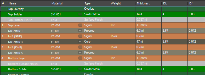
    Cheap PCB material has a more variable Dielectric constant and more absorption in general usually. Oshpark has a good hi freq material (FR408) for their 4 layer boards and JLBPCB has some Rogers materials available (I use 2313)

    Flex pcb material polyamide also has good hifreq properties.

    Bil Herd12:49 PM
    Also before I forget there are great calculators for some of this online. So if I move into wave length these here may help: https://www.microwaves101.com

    https://www.everythingrf.com/rf-calculators

    Bil Herd12:50 PM
    As frequencies go up, the distance represented by a wavelength goes down.

    Bil Herd12:50 PM
    Everyone understand what I mean by wavelenth? Basically Planks constant and why those little holes in yoru microwave oven door let light out but keep microwaves in

    Bil Herd12:51 PM
    250 mhz has a wavelength of 47”, 500 mhz has a wavelength of 23”

    Bil Herd12:51 PM
    Sounds huge right!

    Bil Herd12:51 PM
    When a trace gets to be 1/4th of a wavelength we really DO need to start using atransmission line

    Bil Herd12:52 PM
    (transmission line = stripline = trave over ground plane)

    Bil Herd12:52 PM
    So if we have 500mhz component, anything near 6”/150mm or greater needs to be done as transmission line known as a microstrip and others like stripline, waveguide, etc

    Bil Herd12:53 PM
    so think 500Mhz and 6" , at 500 mhz RADIAN Freq or rise time

    Bil Herd12:53 PM
    the trace officially...

    Read more »

  • Hack Chat Transcript, Part 1

    Lutetium09/25/2019 at 20:06 0 comments

    Well, we've been having some good sidebar discussion here for a bit, but let's kick it off officially and welcome Bil Herd to the Hack Chat. Today we're going to learn about high-speed PCB design.

    Bil, I usually ask hosts to introduce themselves to get things going, but that seems silly here. Maybe just a quick intro?

    Bil Herd12:01 PM
    Hi all, I do the odd video for HAD and recently did a couple about high speed PCB stuff and have another video comoing about PCBs themselves

    Chris Hamilton12:02 PM
    OK, thanks. I am just trying them out to save space as a low power FET, but they are already causing more problems than their worth.

    Bil Herd12:02 PM
    My background was that I had a backyard full of TV chassis in the '70s, never finished high school and ended up designing computers for Commodore Business Machines

    aerispalm12:02 PM
    i actually got away with just making sure all connections are the same length and having a groundplane for 100 mhz qspi, i think anyways i guess its possible that the mcu is throttling .

    Dave Blundell12:03 PM
    experience is the best teacher. nice.

    Bil Herd12:04 PM
    So first let me throw a link to the high speehttps://hackaday.com/2019/01/24/video-putting-high-speed-pcb-design-to-the-test/d Hackaday post which I will be referring to a bunch:

    Bil Herd12:04 PM
    High speed pcb design to me, means understanding about impedance, which is the combination of the effects of capacitance and inductance.

    Nicolas Tremblay joined  the room.12:04 PM


    https://hackaday.com/2019/01/24/video-putting-high-speed-pcb-design-to-the-test/

    HACKADAY BIL HERD

    Video: Putting High Speed PCB Design To The Test

    Designing circuit boards for high speed applications requires special considerations. This you already know, but what exactly do you need to do differently from common board layout? Building on where I left off discussing impedance in 2 layer Printed Circuit Board (PCB) designs, I wanted to start talking about high speed design techniques as they relate to PCBs.

    Read this on Hackaday

    Bil Herd12:05 PM
    When we go up in speeds it means that not only do we have to get fast signals moving around the board but also that the power supply is able to deliver current very quickly while maintain voltage regulation and stability. The two of these things are often referred to these days as Signal Integrity or SI.

    Bil Herd12:06 PM
    A vital part of high-speed design is understanding that the PCB is an entrenched component of the design. It has differing amounts of inductance and capacitance depending on the traces and planes and it can absorb energy or even resonant.

    Frank Buss12:06 PM
    PCB high speed design is black magic

    Bil Herd12:07 PM
    If we have time I can talk about differential signals such as @aerispalm just mentioned.

    Bil Herd12:08 PM
    Hi Frank, I know you well enough to know that Hi Speed / RF design is just an extension of what you already do and know

    Frank Buss12:08 PM
    thanks, I'm a black magic apprentice :-)

    Bil Herd12:09 PM
    First thing I harp on is inductance and the understanding that inductance increases based on the distance to the return path, the width of the trace is minor compared to the distance

    Dave Blundell12:09 PM
    what is the "dividing line" for high speed signals? 50Mhz? 100Mhz? 10Mhz? Like when does it really start to matter?

    Bil Herd12:09 PM
    Inductance resists a change in current, so as you might expect is bad for delivering current quickly. Capacitance resists a change in voltage so good for power supply, bad for signals.

    Bil Herd12:09 PM
    When we talk about frequency we usually mean the rising and falling edges, which typically has more hi-freq content then the fundamental signal itself, I.E. the rising edge of a 10mhz clock might have 100-200mghz of ‘radian/angular’ frequency

    Dave Blundell12:09 PM
    so speed of edges is as/more important than fundamental. Got it.

    Bil Herd12:10 PM
    @Dave Blundell...

    Read more »

View all 3 event logs

Enjoy this event?

Share

Discussions

Ethan Waldo wrote 09/23/2019 at 17:26 point

Can we get a qualification for what is considered "High-Speed" in the context of this chat please?

  Are you sure? yes | no

Evan Juras wrote 09/21/2019 at 15:17 point

Square corners... so controversial!!

  Are you sure? yes | no

Interested in attending?

Become a member to follow this event or host your own