Lutetium
-
Audio Systems Hack Chat Transcript Pt 2
06/02/2017 at 20:47 • 0 commentsDafydd Roche #betteratelectronicsthanmusic
#makemusicwiththeelectronics ;)
Thanks.
do you suppose anyone at Dialog has any interest in prompoting their codecs to the makre/arduino market?
#nomusicwithoutelectronicsandviceversa
I currently make an udio shield with the STGL5000 chip
http://www.dialog-semiconductor.com/content/ard-audio-da7212
The ARD-AUDIO-DA7212 is an 'audio shield' that can be used with a number of MCU development platforms due to its compatibility with the Arduino™ R3 pin layout. The audio shield can be used with commercially available development platforms such as Freescale 'Freedom', Intel 'Galileo', Microchip 'chipKIT' and Arduino.
Read this on Dialog Semiconductor >
PJRC Store
This audio adaptor lets you easily add high quality 16 bit, 44.1 kHz sample rate (CD quality) audio to your projects with Teensy 3.0, 3.1, 3.2, 3.5 or 3.6. It supports stereo headphone and stereo line-level output, and also stereo line-level input or mono microphone input.
do you need linux drivers etc?
"capless headphone driver" I was wondering why you actually need caps at all, what is the benefift of those design that use chunky caps? (total noob when it comes to audio electronics)
or put in a whopping great big cap in between the chip output and the 3.5mm connector
having now sold many thousands of those shields to makers, I'm thinking a future design will AC couple the headphone outputs. The DC offset "virtual ground" is confusing to many novices
hahahahaahahahahah
i Sophi
I'll stay with Senheiser :-P
OMG sophi
then the 2 signals vary up and down relative to 1.5V
We did it a long time ago - at TI I defined the PCM5xxx series of 2VRMS DAC,s and managed 114dB SNR out of a 3.3V DAC with chargepump
I would be happy to know :-P
+1
yeah, more beans please
such a tease
what @Yann Guidon / YGDES said, I would love to know more about audio electronics design. Nothing better than a good project to look at.
Dafydd Rochefor example, 4 - 5 years ago, one of our smartest dudes at TI starts throwing around the concept that if we model a loudspeaker in DSP, we could understand it's current condition, and drive it harder for longer.
one of my first projects 15 years ago was a 16 bits DAC using TI chips...
that because an industry standard technology that TI, NXP, Maxim and others have
We were able to drive 300W peaks out of a 10W amplifier, and it sounded AMAZING
oh ok that is really interesting
@Professor Fartsparkle agreed
how the hell does that work?
I suppose that convolution is one of the best tools that engineers have
AS5766 now uses that technology for mid-power systems, NXP, Maxim and TI have used it for smartphones etc. -- and that's 5 year old technology. The new top secret stuff is even more exciting.
you come back when you want ;-)
+1
Viva La 3.5mm!
not even a slight hint?
The only connector that EVERYONE knows what it's for.
yesssss
exactly :-D
@Paul Stoffregen - not yet. too soon. maybe when I have silicon.
*insert pass me the aux cord joke here*
Oh! Who asked about good tools? I always keep an old ipod touch at my workbench as a simple audio generator.
What app do you use?
I can't use my iphone 7 - anyone know why?! :)
oh, Apple made audio generators ?
Michele Perla connectors, connectors everywhere
lol
Dafyyd : I have a drill, and a 3.5mm drill
I use a simple app called "Signal Gen" - does the job.
@Professor Fartsparkle WHAAAAAAT? Maybe if you use the mic bias ;)
no Audio Precision system ? :-D
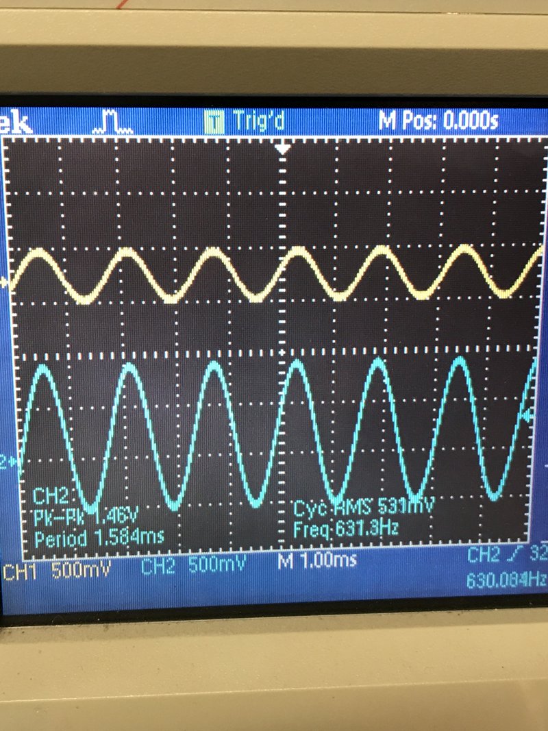
@Yann Guidon / YGDES - sometimes you just need to see on a scope if your audio is passing
*downloads Signal Gen*
well not using an audio source of course :p
in fact, after you told me about the Audio Precision, I was also thinking at getting a good generator
good idea
@audioluxdevices if there's a better app you find, let me know on twitter.
so now : what is a good affordable bench audio generator ?
the AP has a nice generator in it of course. but sometimes you just want something quick 'n dirty to fire into the 'scope and see if the signal is inverting, or gaining up correctly etc
I should grab a hi speed board adc/dac I developed for my previous company
Yann - an used Iphone! :)
;)
and use is with the teensy
seriously - we had an apps guy years ago that debugged a chinese smartphone using an audio analysis app on his iphone.
was able to debug phase and amplitde issues with it
I suppose tools are relative to the use one has to do of it
why not an industrial 16-bits DAC ?
This looks nice too https://itunes.apple.com/us/app/signal-generator/id409241018?mt=8 (not free though)
with consumer audio you can't be sure of noise, amplitude, phase etc...
or even offset
for the ipod, one could just make a .wav file of a pure sinewave and play it :D
@Yann Guidon / YGDES - were you here 2 hours ago? ;)
asleep
he was lurking probably :D
Dang, for a dollar dude, just buy the app. your time is worth more.
come on :D downloading audacity takes 1 minute
one of the things I like about using an old iphone is that the device is electrically floating.
Michele +1
so you don't have ground issues (providing it's not charging)
true true
it runs from the batterty
battery*
but the GSM must be disabled
i use an old itouch ;)
plus, i use it for visual cues, not for proper audio tests.
the good old ipods were nice :) a friend of mine still uses it for music
you mean visual cues in the scopes?
Shulie @Yann Guidon / YGDES Transcript here: https://hackaday.io/event/25110-audio-systems-hack-chat/log/60718-audio-systems-hack-chat-transcript
Dafydd we might continue in private later because sound processing is one of my first interests :-P and I'll have to add a sound output to #WizYasep ...
Thanks Shulie :-)
It's been really nice to have you here @Dafydd Roche , I can't wait to see some of your weekend projects popping up :)
![]()
Agreed, thank you for your time and answering our questions.
@Michele Perla - exactly, classic example, building a small mic pre this week
nice :D
Quick visual cue, does the signal get bigger... throw a few 100mV's in, and get volts out. Hooray - lapel mic will be heard now by my pc!
yes I get it :) I would do the same
thanks for chatting and staying late ;)
+1
meh, my design team is in Edinburgh. they have finished for the day :)
at least I hope they have
that WizYasep sound really interesting @Yann Guidon / YGDES
please ping me when/if that DA7219 chip is available in a non-BGA package
Thank you so much, @Dafydd Roche!
I'd love to support is in the Teensy Audio Library
@Paul Stoffregen not sure we'll retroactively do it.... but future devices, if I have my way, will be available in multiple form factors.
Hey, if Raspi can be $5 with loads of BGA's, can't you do BGA's too ? ;)
I avoid BGA :-/
@Shulie Tornel - thank you for hosting me, and to all y'all for your questions and banter.
@Yann Guidon / YGDES - me too, but it's not that scary. I need practice.
Dafydd Roche DA7219 has been done so it can be soldered on a 2 layer board, using RouteEasy technology. (pins are W in formation)
well, apparently I can do BGA (or more precisely the contract manufacturer I use), at least lower density, as Teensy 3.5 & 3.6 are doing pretty well with a BGA144 package
but it's not just about me...
@Paul Stoffregen - I did a hackercamp in SZ a few years ago where they taught me to do BGA's
unlike Raspberry Pi,, where you can't get the chips from Broadcom unless you make internet routers or cable set top boxes....
people do use boards like Arduino and Teensy as the startign point for their low-to-moderate volume product designs
![]()
-
Audio Systems Hack Chat Transcript Pt1
06/02/2017 at 19:25 • 0 commentsDafydd Roche Paul - that's because the parts (if it's the same as other semi guys) aren't designed, verified, bench tested or prod tested to guarantee drift
drift tests costs seconds on a tester, and in many cases, multi-temp test runs, which costs $$$$$
in the 90's, I went to see Bob Pease talk once... which was of course 10 minutes of Bob intersperced with 2 hours of National Semi marketing managers
there's a reason why industrial DC converters cost so much. In many cases, the additional test time is one of the reasons
I think that the best is to leave audio codecs for audio, while using DC specific converters for, well, DC applications
and he said something that stuck: all datasheets are from the marketing folks, sales pitches to get you to buy the part, pretending it was made for everyone in the world, when in fact they usually designed it for one big client
Paul Stoffregen do you suppose DC offset could be measured at startup and nulled out?
Shulie: @Dafydd Roche Thanks for joining us today! Can you please give us a short bio about yourself, your expertise?
there's temperature drift to account for
like use an analog switch to disconnect the input signal and short the input to analog ground, and then take a few thousand readings and store the average once it settles?
Hi everyone. My name is Dafydd Roche. I'm a Audio Systems and Strategic Marketing Manager for Dialog Semi. I have 16 years of experience in this game, having worked most of them for TI, and more recently Dialog Semiconductor. I spend my spare time tinkering with Pro Audio products and am one half of Expat Audio, a hobby business making PCB's and modules for Pro Audio guys who want to build up their studio's with DIY gear. At Dialog, I define new audio IC's, I did the same at TI previously. In my spare time, I design, layout, manufacture, pick and place and design enclosured etc for Expat Audio.
the board may or may not be always at the same temperature
that's a nice bio indeed @Dafydd Roche :D
wow, that's some audio IC experience indeed ;)
Paul - You have no idea how many customers I used to answer on our audio converters use in industrial systems.
They would see 130+dB SNR, and want to try and get it at DC... it was a hot mess.
Is someone from design lab online?
Hi all. :-)
yeah, who wouldn't want 21+ bits for cheap!
:-)
24 bits A/D converter ?
@Paul Stoffregen The last ADC I worked on at my previous employers integrated the usual PGA, ADC, DSP Core etc... we had an internal request to use it for DC measurements, which our team couldn't commit to, so the other interested party ended up having to make the equivelent circuit from discrete components... at a 15x cost.
@alusion not technically, but we can talk when this is over
Do you know much about cabling for audio in large venues?
@Benchoff okay PM me later, I have some ideas for the virtual/physical hackerspace vision.
@Joshua Reisenauer - some. Mainly from doing live gigs of my own over the years... but nothign "Large" like stadium size. I'd say the biggest issue you'd have in capacitance in teh cabling and ground potential differential between equipment.
I just spotted a question from Brian McEvoy for a cough button for an XLR mic system...
"What do I need in a "cough" button on an XLR mic system to suppress the pop when I press it?"
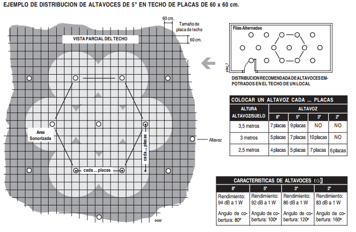
Audio cabling in large venues: first, star distributions to reduce audio delay echoes, with replication for multiple edge cells
Shulie: What is a cough button? :)
"I move away from the mic to breathe in"
You have two potential sources for pop, first is phantom power being quickly charged and discharged through the front end capacitors and secondly, that quick pull to GND from the signal being non-GND.
Audio cabling in large venues: second is the sincronization of generated signals on each star.
both of these are caused by the rapid switch to GND. never a good thing. You might be better off using a FET that is slowly turned on. (by slowly, I still mean way less than a second, but with way less switch bounce and slow switch rise time).
I would be tempted to experiment with putting the FET between the + and - of the inputs, rather than switching to GND.
Lets say you have repeaters set up every 600 feet, with 1 cat5e cable for every 8 speakers. Do i need thicker wire, or is cat5 OK.
There's an awesome book, which I consider to be the audio bible in this respect called Small Signal Audio Design by Douglas Self.
Dafydd Roche he has a great section on mute circuits, where he employs J111 JFETs and 4066 logic switches.
Phew -- off to a great start. Benchoff, I'll come back to the audiophile crap in a moment ;)
@Jordan Bunker -- "When you say that you "define new audio ICs", what exactly does that entail?"---
@Dafydd Roche , thank you for the all the info! You know what I'll be doing this weekend.
![]()
Dafydd Roche It means talking to a hellavaload of customers (folks making smartphones, laptops, wireless speakers, guitar amps, office printers etc) and learning about their current audio architecturs, studying what's broken or what they had to compromise, then starting the process of defining a next gen chip that fixes those issues quickly and easily.
![]()
Audio cabling in large venues, for cells...
thanks.
So you end up with a block diagram, IP specifications and goign back to customers with "ok, how about this? does this potentially solve your problems? how much do you think that's worth? ($$$$) -- then comes the business case that comes with it, and the negotiation with design teams to understand how long it'll take to design, how much it'll cost to design and sell, and some math to decide whether it's worth doing the design or not.
last thing I wanna do is hog this conversation with DC offset talk... but, if no other questions pending... the eurorack synth folks don't need anything like 1 LSB DC offset accuracy. The common case is control voltage with 1V (of a 20V full scale analog range) mapping to 1 octave. Keeping the DC offset under 1 cent (1/100th of a semitone, or 0.83 mV) is probably quite acceptable. So that's an allowable DC offset of about 1/24000th of full scale according to my back-of-a-napkin math...
The it's a matter of arguing and discussing the compromises that go into the chip. for example -- DC accuracy, as @Paul Stoffregen was asking about.
@Dafydd Roche Interesting!
DC accuracy is one of hte items compromised quickly and early in most converter projects, as it's not required in 99.9999% of the audio applications. Even a small DC offset (mV's) is acceptable etc.
Product Definiton, and the new product strategic marketing is a constant balance of making a differentiated part easy to use, easy to design, quick to market, and have enough broad market appeal to keep everyone happy
Where can I leard PCB design? My background: I'm a former recording engineer, and currently a computer engineering student. I've just finished basic circuit classes and FPGA design. Next semester is VLSI design. But the university has no classes in PCB design, which I thought was a huge hole in the program. So where can I learn it on my own?
and to do it faster and better than your competitors.
yeah, but I wanna do pretty much the exact thing you said not to.... figure out a dirty hack to use cheap codecs for this application, which needs about 15 bits DC accuracy
@Paul - I get it dude. Is your challenge mainly on the DAC side, or on the ADC side too?
@steveco
@stevecorey I had the same issue at university
both sides are important
do you want to learn? then grab kicad or eagle and start making your own schematics and circuits :)
@stevecorey - I found rolling up sleeves and getting on with it. Some great Eagle tutorials out there, but unless you are making real circuits that are important to you, sandboxes are useless.
@Paul Stoffregen I still have to look in DC converters for the Teensy for my application as well
@Paul Stoffregen - DAC side isn't so hard. Most DAC's are either based on summed current segments or on switched cap architectures.
I would like to be able to mux like 16 CV/Gate channels using the integrated DAC on the teensy
In Current Segments, you typically randomise at high speed which of your multiude of current segments are on. Therefor, your offset and noise is randomized (averaging it lower).
but expectations can be lowered... even in the 13-14 bit accuracy range for DC offsets and gain would probably please a lot of folks in that that admittedly very small niche market
your main source of offset is going to come from the voltage reference for the current segments, and from any DC offset in your I/V stage.
@Benchoff is this audiophiley enough for you? ;)
DC offset in your I/V stage, if it's external (such as if you're using a PCM179x DAC) can be controlled.
No, it's still based in reality.
@Dafydd Roche it's not audiophiley enough because you're not talking about warmth of tone and clarity
:D
Your voltage reference for your current segments is external on some devices, manufacturers will typically have a pin that you can put a whopping great big cap on to stabilize it.
do you believe it's realisitic to measure and calibrate out the offsets, at least on a time scale of 2-8 hours?
ADC side is a different story, especially if there's an integrated Programmable gain amplifier.
@Paul Stoffregen - sounds reasonable, but don't base a business case on it! ;)
@Paul Stoffregen the best, always reliable way would be to have thermistors around the board and use that to estimate the dc variation due to heating of components
temperature is the main PITA with these systems
Shulie: Anyone joining us needs a transcript, here it is: https://hackaday.io/event/25110-audio-systems-hack-chat/log/60718-audio-systems-hack-chat-transcript
if you're always hanging around room temp, in the data I've seen previously, you should be fine
I used a control like this for the first time at my last job
Thanks @Shulie Tornel
if you're hanging out next to a power amplifier - common enough with audio, then you'll need to calibrate ona regular basis.
but not for audio, it was to keep constant power on a laser diode
yeah, temperature change is probably a big problem
@Dafydd Roche that, and also we should consider intense uses
it's a major issue wiht resistors for instance (getting to it @benchoff!)
someone could use keep the board running for around 12h every day in small enviroments
lots of Audiophiles don't like using SMD resistors, claiming that htey increase distortion.
@Dafydd Roche I still fight about that every with a friend of mine, he's a full-analog one,
yes, you can't trap harmonics in the crystal lattice...
he makes tube amps replicas
main issue is that people like to throw ±15V signals through them, where the small temp changes in them cause the resistance to change...
I want to put extactly +-15 V on my boards
I have reason to believe that if you had through hole resistors of the same size, they'd have the same issues in many cases.
but signals should be around +-6 V
so I think, and I've said this on the amp hour too...
if you're only throwing small signals around the place, SMD is absolutely fine.
worst case, is a 1206 device, metal file for accuracy.
use* not is
also let's not forget that through hole resistors add parasitic inductances and capaticances due to the pin lenghts and thru hole vias
I'm a little skeptical that thermal changes occur faster than 20 Hz
@Paul Stoffregen what if something is failing hard?
or what if the board is inside a cramped up battery operated device, under charge?
not to mention the parts the audio band people can really hear
@Paul Stoffregen - fair enough
then again, audiophiles probably believe they can hear well below 20 Hz
consider this though, 1 lsb in 16 bit (noise at -96dB) is a 1.52588E-05 change in voltage
cause my a thermal change.
by* (sorry, the keyboard is a little dyslexic)
it doesn't take a big thermal change to shift the resistance a tiny bit and really mess up the feedback in your opamp gain etc.
true, true
in Semi design, the components we have are utter tripe
what do you mean?
analog designers spend more circuitry compensating for other crappy components than on the simple design itself.
ok now I see your pointe.g. resistors have TERRIBLE differences from wafer to wafer
what, no laser trimmed michrome metal layer?
20K is never 20Ohm.
20KOhm
yes of course
there's tolerances
I don't see the smartphone guys paying for the extra processing ;)
what we do see in Semiconductors is that if you specify multiple 20KOhm resistors, then they will all drift together.
so making a VCC/2 is reasonable, because if both resistors drift together the same amount, you still maintain teh right voltage...
but imagine a gain setting resistors, or an LDO voltage setting resistor. you have to find a smart way to compensate for device to device changes, as well as temp changes etc.
s common centroid layout commonly used?
those guys in design are miracle workers.
@Paul Stoffregen as a guy who doesn't get his own access to the Process Development Kits (the "componennts" from the fab", I can't answer that. They don't give us marketing types access to the linux servers and design tools ;)
not enoguh undo buttons
ok I got a question
@Brian McEvoy - Back to your cough switch. Have you considered doing it in the digital domain? you'd get zero crossing detection and avoid the phantom switching stuff quite easily.
which is not exactly related to the theme :) how could someone make distortion measurements easily at home?
@Brian McEvoy you could do it quite easily with a device like a DA7219 by simply changing the volume control with a microcontroller
@Michele Perla - that is a really realyl hard one.
heh :D I'm asking because I will need that in a while
@Michele Perla SNR is pretty easy, but without calibrated tech, it's tough. you have to know what you're expecting to compare it.
exactly, that's the point
@Dafydd Roche , I suppose it would be more practical to do it in the computer. I knew cough buttons and Push To Talk buttons existed so it seemd like the most logical place to start. I will look into that first though. Thak you again for the advice!
@Michele Perla I know it sounds like a cop-out, but I would look at getting an used Audio Precision System one, and one of the new USB controllers availabel on DIY Audio Forum
I read online about this Audio Precision System already
@Michele Perla better to buy the right tool than to lose another 6 months making a tool, then questioning it's accuracy every time you use it
@Brian McEvoy If it's into a PC, build a simple Midi control button using an arduino that will send a midi command to your DAW.
yes I get your point. I was already thinking of making a
I think I will have to rely on my crappy oscilloscope for now
and kinda guess the values
can your scope do FFT's?
yes it can
THD typically comes in high frequency components. by measuring a before nad after FFT, if you spot multiple high freq components in the FFT, it may help
@Dafydd Roche , that's right up my alley!
aren't most scopes only about 8-10 bits resolution & noise floor?
right
if it's THD@1K, then you'll need to build an analog notch filter, then up the gain
again - lose months for something you'll constantly have doubt over.
oh I didn't think about the notch filter
heh I should get a spi 32 bit ADC and interface it with the teensy
i recently spotted this: https://quantasylum.com/products/qa401-audio-analyzer which looks quite nice... but for double that, you coudl get an AP.
the AP will ast you 10 years minimum
I am seriously considering buying one
sometimes, you just need the right tool and get it once
EXACTLY
I had a similar discussion with a friend three days ago
@Dafydd Roche Along this same theme, what do you consider to be the base set of tools you would recommend using for desigining and shipping an audio product?
I've made the mistake of going cheap so many times and regretted it.
he's still learning how to make electronics and stuff, and he got a cheap soldering iron that broke after 2 uses
@Jacob -- oh wow. I need a minute for that one.
even if I always told him to keep the money and buy a decent one once and for all
:D
@Jacob Creedon that's a really nice question
/me fills his cup of tea... this'll take some typing.
Shipping an Audio product is about 5 phases, Design, Prototype, Software Integration, HW performance testing, AT (assembly and test)
I'm not going to touch teh true hardware side (enclosures etc), that's another chat completely.
Design phase - you'll need your usual PC and so on, but don't forget you'll need some analysis tools to measure some of the eval boards that you're going to request from the manufacturer.
So lets say I was in @Michele Perla's books... about to design a codec board. First things first -- order the AKM eval board, then do yourself a favor and order a DA7218 codec board whilst you're at it. You can't design parts in from the front page of a datasheet. the devil is int he detail. What @Paul Stoffregen mentioned earlier about datasheets is somewhat true. the first page is designed to get a bite. teh rest of the datasheet hides the real truths of the part.
Assume @Michele Perla loves the Dialog Semi part, because who wouldn't, right? He designs his boards, sends them off and gets them back. He's going to need a few "wet bench" supplies to build the boards. I *love* the Hakko 936 and the version that integrates a hot air wand. Lovely soldering irons. Mine is over 10 years old, and runs like a champ. Get a range of power supplies - you'll need one that can handle ±18V and another that can drive 3v3/5. Big caps accross outputs to filter noise.most of the circuitry in the analog domain doesn't have fast changes in power demands, so even an old school used power supply will be fine. the digital rails are a little different. For your software integration - especially for SPI/UART/I2C debugging, a logic analiser in a MUST. I also like to use a crappy arduino uno to give i2c parts the 3 finger salute to get them up and running.saves having to get things like Linux up and running on your application processor.I'm quite fond of the salae ones. very well built and the software is nice too. so you've got your audio prototype booting up, codecs and amps configured over I2S... now you have to do a performance test. This is where having a tool like an audio precision is a god-send. Not only can you do all of your classic audio tests (SNR/THD) etc with it, but you can also set up testing scripts to do the same testing on your production units. Once it's scripted, your assembly technicians don't need to know what they are doing. they simply plug in the unit, and click "go" on your software and it'll green screen or red screen a pass or fail. GLORIOUS! Building test jigs is a whole other conversation. I have some video's on youtube on my little test jigs for Expat Audio.
@Joshua Reisenauer -lets have a look at your shielding question, "Sheilding has always been a problem for me. I know everyone says to use mini faraday cages. Are there ways around this, other than switching to digital."
how many systems are you building?
Hi everyone (hello also to @Paul Stoffregen !) -- I am here with interests in shielding as well. We work a lot with audio applications that also interface with addressable LEDs that draw large amounts of low voltage current. We often run into issues with noise entering the the audio path. Often we can't change the audio path circuitry since it's outboard external hardware. We are looking into power supply filtering and using shielded wire for our power lines. Any advice along those lines? Thank you!
@audioluxdevices is the noise being coupled through EMI over the air, or by the ground currents from your LED's?
ground return currents *
External speaker system, rats nest right now on punch down system.
@Dafydd Roche -- I've done some tests with the LEDs very close to sensitive audio components like mic capsules and have not encountered all that much EMI over the air, I suspect it's related to ground currents.
We have about 96 home runs. 8 for each repeater. We made solid contact to all boxes, for return.
most systems I've seen with problems don't actually come from shielding issues (like audio signals too close to a power transformer). Most come from ground return currently. LED's, especially in things like VU meters can pull hundreds of mA from source to GND. IF that GND is shared with your sensitive audio circuits, then GND is no longer your magical, mystical, zero volts...
it's actually causes a voltage to be developed over the low impedance.... and worse, as the led's jitter on and off, that voltage moves with it, coupling into the audio...
I'm a huge *huge* fan of Henry Ott's books for this stuff. he talks about smart system partitioning. if you have wildly fluctiation current path, give it a path back to the power source that doesn't pass through your sensitive audio circuitry
yeah, large addressable LED projects have huge ground currents, dozens and sometimes even hundreds of amps, with a strong component at ~420 Hz (the PWM frequency most of those chip use)
smack in the audio range ;)
isolate your control paths too if you can. opto isolators can be your friend here. :)
so do the isolation onthe I2S signals??
So follow each return path to find the cause?
That's exactly the issue @Dafydd Roche. Could you give a brief example of giving the LEDs a path back to the power source?
opto isolate your PWM output from your microcontroller, then have a separate ground return path (don't share the ground) between the uC and the LED circuits
@Paul Stoffregen I know isolation on I2S sounds extreme. There are solutions for it though. :)
Oh boy, thats it. We have common return paths on my project.
I've seen some folks use S/PDIF for this.
Will check out Henry Ott's books, if any particular titles come to mind, that would be helpful. :)
http://www.hottconsultants.com/EMCE_book_files/emce_book.html
![]()
EMC Books
Read this on Hottconsultants >
i wish there were sound effects possible on this chat.
well, I2S is usaully 1.5 to 3 Mbit/sec
the slower addressable LED protocols are 0.8 Mbit/sec
the faster ones range from 4 to 20 Mbit/sec
but the power isn't being drawn at that rate, right?
the communications prototcol should be low power.
it's not good 'ole PWM from a microcntroller pin to a big transistor... it's a high speeddigital protocol sent to LEDs with controller chips insde each one
(or low current)
@Paul Stoffregen my old employers used to have some parts that might solve this: http://www.ti.com/lsds/ti/isolators/digital-isolator-products.page#p740=2500;4200&p2877=4/0;3/1;2/2&columnOrderString=o1,o4,p740,p1950,p2815,p2738,p2877,p2864,p169max,p106min,p106max,p2183typ,p480,p1498,p1192,p2954,p1811,p1130,o7
@Paul - you and your WS2812's? ;)
Blinky things are awesome!
:)
@Dafydd Roche nice parts. I was thinking of using them on USB ports as well
yup - so many awesome LED projects made from those cheap LEDs
yup.
Thanks for the insights @Dafydd Roche -- I need to do some research into how to set up unique ground paths. You mention the uC and the LED circuitry ground needs to be separated but usually the grounds need to be tied, so that's confusing.
Thank you.
Last call for questions? We have another 10 minutes for this Hack Chat. :)
@audioluxdevices uc and LED shoudl be shared.
Dafydd Roche you're audio paths need to be separate. or make your audio paths differential.
or make your audio paths differential.
That's what I figured. we did that a few years ago with PCM1865 in a BT speaker with Aux in.
What did you use to create your differential audio paths?
we actually had the source come in, and treated the source GND as the negative differential input.
hum-killer
ah-ha
Michele Perla @Dafydd Roche perfect :D
this actually solves some of hte long distance stadium audio stuff too...
How PSSR really affects noise output?
I will keep that in mind.
quick Dialog product question - are all the codecs only available in BGA packges?
PSRR*
by treating a single ended "ground connection" as a negative input to a differental input, the noise common both source GND and source audio gets cancelled
@Paul Stoffregen - they are all BGA. I'm working on getting them to be a little more "broad" :)
^ this
Some wiring tricks onto intensifying sound?
To troubleshoot ground noise issues, do you measure the ground voltage? Or how would you narrow down the issue?
@Paul Stoffregen - they are also less than half of the power consumption of competing devices. I need a pair of stone tablets and a mountain to yell that from
(happy to let other folks now get their last minute questions in before times up). Thank you @Dafydd Roche !
@audioluxdevices - That's an awesome Q.... I don't have hte answer, but i'm sure Mr Ott does.
Duly noted :) Going to check out those books, thank for the link.
@thekidtonystark mix a little bit of the inverted LEFT signal into the RIGHT signal and vice versa. Instant 3d effect
cheap, cheerful. a pair of opamps and you're done.
Nice, might try that in the software domain as well for mixes.
@audioluxdevices it's old school stereo widening. 2nd year uni course ;)
Audio Systems Hack Chat
We're talking about audio systems and the ICs used to develop these systems in this chat!