Mike Szczys
-
Workshop Details: Reverse Engineering
11/07/2014 at 17:33 • 0 comments![]()
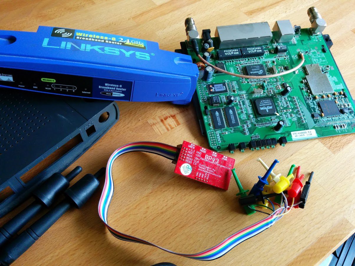
The dark art of reverse engineering runs long and deep. But a core set of skills can be almost universally applied. We've selected the hardware shown above to try out these skills during the Reverse Engineering workshop.
Click Here to download the Workshop Guide
We'll leverage the Linksys wrt54g router as a test subject, and use one of our go-to tools -- the Bus Pirate -- to poke at it. Here's what we have planned for the device:
- Connect the Bus Pirate to the router's UART to see what information you can get from this digital portal
- Intercept the boot sequence
- Dump the contents of flash
- Dig through the binary dump and see what there is to be found
Bring your own hardware to hack
We have a limited number of routers to play with. It would be very helpful if you could look through your junk bins and find some electronics that you'd like to reverse engineer. [Sprite_TM] will be on hand to lend advice to your hacking adventure, as well as to help out those who are exploring what the routers have to offer.
-
Workshop Details: Computer Vision
11/07/2014 at 16:56 • 0 comments![]()
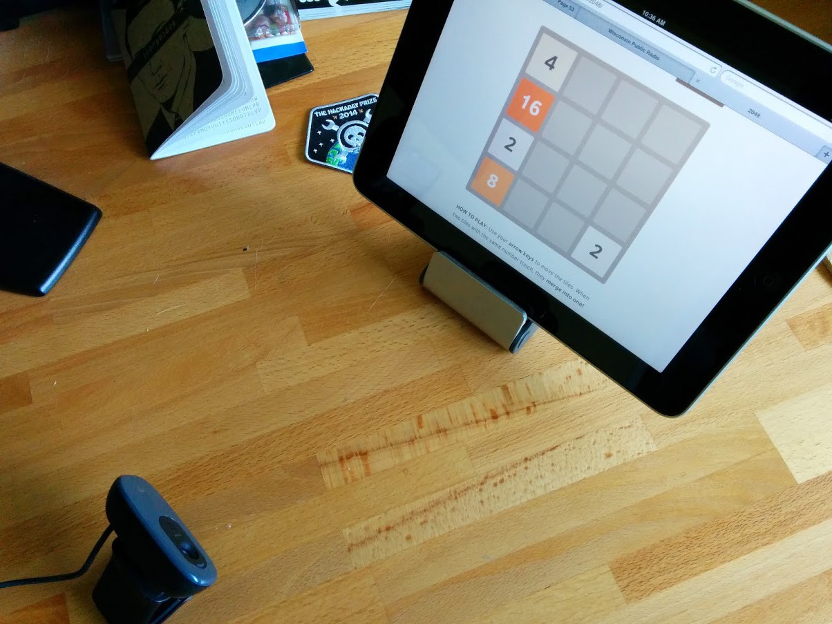
The Computer Vision workshop encourages you work out how to get a computer to recognize objects in an image. One of the fastest feedback loops for this is to use a webcam and you can see the setup above shows off the core of this workshop.
Bring your tablet or smartphone
We will have webcams on hand. Your laptop webcam may also be used. But this will work best if you have a second screen for the camera to look at. Bring your tablet or a smartphone along.
Premise
![]()
The beginnings of Computer Vision are all about recognizing patterns. As a working example we suggest building a bot that will play the game 2048 for you. This is pictured above and has several things going for it:
- a well-defined grid that makes it easy to recognize where the tiles are located
- Different background colors for different tile values
Your goals for the afternoon include:- Install OpenCV: http://opencv.org/
- Load up 2048 on your table or smartphone: http://gabrielecirulli.github.io/2048/
- Use OpenCV to grab an image from the web cam and recognize where each tile is located
- Parse the values of each tile
- Write logic that will tell you the best move to make next
Simple
If you're already an OpenCV master and find this too simple, impress us by bringing along your own hardcore examples to work on. Here are some suggestions to get you thinking:- Face tracking (easy) and facial recognition (harder)
- Color tracking (bring along a tennis ball or other object for motion tracking)
- Handwriting recognition:
- The options are never-ending.
-
Workshop Details: Moog
10/30/2014 at 16:05 • 3 comments![]()
Meet the Moog Werkstatt. This hackable analog synthesizer is the centerpiece of the Moog workshop. Moog have kindly offered to loan us 10 units for the day which we'll be able to hack on, learn a bit about how audio waveforms are produced, and alter the output by connecting your own circuits. Get ahead of the game by looking at some of the Moog tutorials.
If you do not have a workshop ticket:
Bring your own synthesizer along, or build one using your favorite microcontroller.
If you're just getting started with embedded, grab an Arduino board and bring it with you. There are already numerous examples of how to make synths using the popular platform.
Those who have more experience with embedded, we'd love to see you working on some homebrew chiptunes hardware!
For those that already have Moog Workshop tickets:
There will be a variety of hardware provided for you to prototype with on the day, here's a list of some of the things we will have available that have been kindly provided by the Moog workshop sponsor Mouser:
- Olimex EKG-EMG Shield
- Rolling ball inclinometers
- Force sensors
- ADXL335Z 3 axis accelerometers
- A variety of Soft pots
- MCP4911 DAC
- A variety of linear and audio pots in 10k and 100k range
- A variety of slide pots
- Microchip 23k256 ram chips
- A variety of opamps
Of course we'll also have a random selection of resistors, capacitors and other basic components like logic level shifters.
![]()
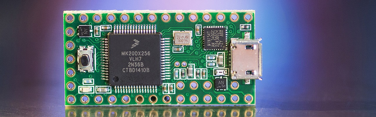
In addition to the Moog itself we will have Teensy 3.1 boards on hand to interface with the synthesizer. This board can be programmed using the Teensyduino framework: https://www.pjrc.com/teensy/td_download.html We will also be providing a number of the Teensy Audio Adapters to make it easier for you to pull in and push out audio.
We will also be providing some Arduino Uno's, along with the excellent Analog Shield from Digilent giving you 4 full 16bit ADC and DAC's controllable from your Arduino IDE. So you might want to checkout the library and demo code for that.
Things you should bring
We can't provide everything, while we're trying to get most things you'll need for the day, additional things you might want to bring with you include:
- Headphones - we'll have a few, but bring your own, and 3.5mm to 1/4" adapters if you have them!
- Midi CV controllers - we have no keyboards, so bring one if you want to get the most from your Moog.
- Effects pedals - always useful if you want to make noise or act as controllers
- Extra breadboards - we'll have small breadboards on hand, but if you have them bring your own
- Any interesting audio devices or sensors you think you might need
Examples of previous hacks
There just aren't that many examples of interfacing a microcontroller with the Moog. Let's change that with this workshop. Start researching the Moog and any hacks you'd like to perform using the hardware. Here are some examples to get you started:
Noise Generator:
This one is demonstrated by the Moog crew themselves: http://www.werkstattworkshop.com/?q=projects/noise-generator
Spoofing the keyboard:
The Teensy 3.1 can be used to emulate key presses on the Moog allowing you to script the playback of notes so that both of your hands are then free to manipulate the waveforms during playback. [Peter Churchyard] published an example of this hack: http://moddersandrockers.com/werkstatt/1.php
-
Workshop Details: Roboto
10/29/2014 at 21:17 • 3 comments![]()
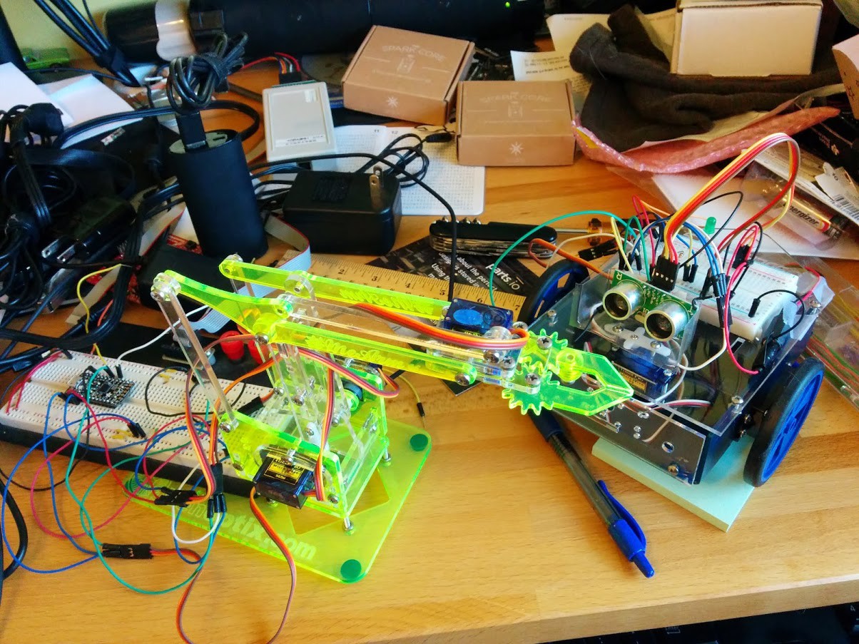
You choose between a robot arm or a two-wheeled rover, then pair it up with a development board for a microcontroller that is new to you.
The challenge is to connect the bot to the board and then write the firmware to accomplish a simple task. For the robot arm you'll need to pick up a small object and place it in a box. The rover uses an ultrasonic distance senor as its only input. Will you be able to navigate the maze using this crude level of sensing?
Before you arrive:
Both of these robots use servo motors. To succeed at these workshops you will need to use properly timed PWM signals to drive them.
Make sure you hit the ground running on the day of the workshop. Before you arrive do as much research as you can about the boards listed below. Look for servo libraries or research implementing the servo timing yourself. At the very least, set up the toolchains on your computer so that you'll be ready to start coding as soon as you sit down.
If you do not have a workshop ticket:
It's okay, you can still come and have a fun time in several ways. First off, head over to the Hackaday Munich page and get an "All Day" ticket. Now here are your options:
- Bring your laptop computer with you
- We will have more development boards than there are robot bodies. Grab one and decide your own programming challenge. It would help to bring along your breadboard, jumper wires, and some LEDs (or other hardware to play around with). The GPIO levels for most of these boards is 3.3v
- If you already have a wheeled robot or robot arm bring it along! You can write new code for the controller you already have, or connect one of these devboards
For those that already have Robot Workshop tickets:
Get those embedded programming chops ready, this is going to be a ton of fun! Pull out the laptop you plan to bring with you to the workshop and load up the toolchain you would like to use. This will save you a ton of time the day-of the event. Here are details on the development boards we have lined up so far:
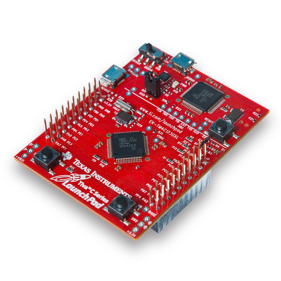
Texas Instruments Tiva C Launchpad
![]() TI has committed 20 of their Tiva C Launchpad boards which features the TM4C123GH6PM which is a 32-bit ARM Cortex-M4 running up to 80MHz with 256 KB of flash and 32KB of SRAM. This chip includes hardware-PWM generators which will come in handy for these challenges.
TI has committed 20 of their Tiva C Launchpad boards which features the TM4C123GH6PM which is a 32-bit ARM Cortex-M4 running up to 80MHz with 256 KB of flash and 32KB of SRAM. This chip includes hardware-PWM generators which will come in handy for these challenges.Resources:
- Product page: http://www.ti.com/tool/ek-tm4c123gxl
- Development tools:
- Code Composer Studio is available for free (code-limited): http://www.ti.com/lsds/ti/microcontrollers_16-bit_32-bit/c2000_performance/tools_software.page#ccstudio
- Development using a Linux machine is possible.
- You will need to install an arm-none-eabi-xxx toolschain.
- We asked on Twitter about this and the pre-compiled toolchain maintained by Pebble (the smartwatch company) was suggested: https://developer.getpebble.com/download-sdk/linux/
- It has been suggested the the arm-none-eabi-gcc package in the Ubuntu 14.04 repos is not up to day. You may consider trying this PPA: https://launchpad.net/~terry.guo/+archive/ubuntu/gcc-arm-embedded
- Install OpenOCD (to flash the binary to the board)
- A template for compiling your code is found here: https://github.com/szczys/tiva-c-launchpad-template
- Don't forget the TivaWare Package which includes header files and peripheral libraries: http://www.ti.com/tool/sw-tm4c
- You will need to install an arm-none-eabi-xxx toolschain.
TI has also committed 20 SimpleLink WiFi Boosterpacks and 20 Sensor Hub BoosterPacks.
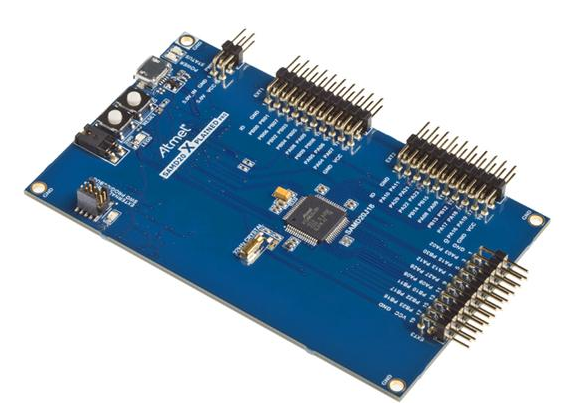
Atmel SAM D20 Xplained Pro Evaluation Kit
![]()
Atmel has committed 20 of their SAM D20 Xplained Pro evaluation kits. These feature a ATSAMD20J18 which is an ARM Cortex-M0+ running up to 48 Mhz with 256 KB of Flash and 32 KB of SRAM.
Resources:
- Product page: http://www.atmel.com/tools/atsamd20-xpro.aspx
- Development Tools:
- Atmel Studio: http://www.atmel.com/microsite/atmel_studio6/default.aspx
- Development using a Linux machine is possible:
- Guide: https://plus.google.com/+AndreyYurovsky/posts/5JTehC7ngTq
- I used this PPA for the toolchain: https://launchpad.net/~terry.guo/+archive/ubuntu/gcc-arm-embedded
- There are some typos (remove the '4' in the OpenOCD config file name, etc.)
- I had to explicitly enable cmsis-dap when configuring OpenOCD: ./configure --enable-maintainer-mode --enable-cmsis-dap --enable-hidapi-libusb
- If you get an error finding the libhidapi-redraw.so.0 see here: http://karibe.co.ke/2013/08/setting-up-linux-opensource-build-and-debug-tools-for-freescale-freedom-board-frdm-kl25z/
- Guide: https://plus.google.com/+AndreyYurovsky/posts/5JTehC7ngTq
Examples:
- Atmel's API for PWM: http://www.atmel.com/Images/Atmel-42123-SAM-D20-D21-Timer-Counter-Driver-TC_Application-Note_AT03263.pdf
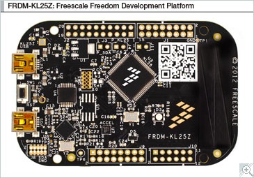
Freescale FRDM-KL25Z Freedom Board
![]()
Freescale is sending their FRDM-KL25Z Freedom Board to the Hackaday Munch Embedded Hardware Workshop. This board features the MKL25Z128VLK4 which is an ARM Cortex-M0+ chip that runs at up to 48MHz with 128KB Flash and 16KB SRAM.
Resources:
- Product Page: http://www.freescale.com/webapp/sps/site/prod_summary.jsp?code=FRDM-KL25Z#
- Development Tools:
- Evaluation versions of IDE include CodeWarrior and Keil: http://www.freescale.com/webapp/sps/site/prod_summary.jsp?code=FRDM-KL25Z&fpsp=1&tab=Design_Tools_Tab
- You can use the mBed environment: http://developer.mbed.org/handbook/mbed-FRDM-KL25Z-Getting-Started
- Requires a simple firmware upgrade: http://developer.mbed.org/handbook/mbed-FRDM-KL25z-Upgrade
- Linux Bare Metal template: https://github.com/payne92/bare-metal-arm
- We haven't tested this yet
- It has been suggested the the arm-none-eabi-gcc package in the Ubuntu 14.04 repos is not up to day. You may consider trying this PPA: https://launchpad.net/~terry.guo/+archive/ubuntu/gcc-arm-embedded
- Mega-resource for GNU ARM tools for these Kinetis boards: http://mcuoneclipse.com/2013/07/20/dyi-free-toolchain-for-kinetis-part-1-gnu-arm-build-tools/
Examples:
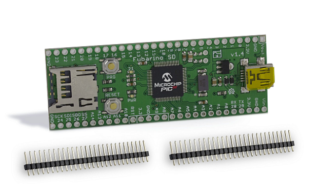
Microchip TCHIP010 Fubarino SD Board
![]()
Microchip has offered up 20 of their Fubarino SD Boards. These Open Hardware boards host a PIC32MX795F512H chip which runs at up to 80 MHz, boasts 512KB of Flash and 128KB of RAM.
Resources:
- Product page: http://www.microchip.com/DevelopmentTools/ProductDetails.aspx?PartNO=TCHIP010&utm_source=MicroSolutions&utm_medium=&utm_term=&utm_content=&utm_campaign=Fubarino+SD+Dev+Board
- Fubarino website: http://fubarino.org/
- Program using MPIDE (a fork of the Arduino IDE): http://chipkit.net/started/install-chipkit-software/
Hobby Servos and Ultrasonic Sensors
The Challenge in this workshop isn't merely to get a toolchain for an unfamiliar chip architecture working. We actually need to so something with the hardware. Blinking LEDs is always a good proof that everything is working, but we want to go further. Let's drive some robots using servo motors. If you're awesome at that you can also try your hand at reading from an ultrasonic distance sensor.
Controlling Servo Motors
Servo motors are a great step beyond driving an LED because they require precise timing. Here's the workflow I would recommend for developing a servo motor driver:
- Blink an LED
- This shows that you know how to control the GPIO pins. If you blink at 1 second intervals it is also a simple check to let you know that you are (probably) correctly calculating a delay based on the system clock
- Dim an LED using PWM
- Whether you're using hardware or software based PWM, dimming an LED gives you simple visual feedback that you've got it working
- Figure out your servo timings
- Now alter your LED dimming code to use a period of 20ms with a pulse width of 1ms and 2ms. I like to use a delay function to change the duty cycle between the two values. If you look closely you should still be able to see a change in the brightness of the LED
- Testing and troubleshooting
- Connect it to one of the servo motors
- Make sure you are using an in-line resistor to protect the logic circuitry inside the servo in case you've connected it incorrectly
- If the servo isn't moving, don't leave it plugged in. Instead, head on over to the oscilloscope and measure your signal to get feedback on the timing problem
- Connect it to one of the servo motors
Reading an Ultrasonic Distance Sensor
US-100 Datasheet (kind of)
There is a quick tutorial on reading this sensor using an Arduino and the NewPing library: http://arduino-info.wikispaces.com/UltraSonicDistance
The New Ping library itself shows just how easy it is to read from this sensor. You can read the sensor using as UART if the jumper on the back side is in place. But it is very easy to read it without the jumper in place by measuring the pulse-width. You pull the trigger pin high-then-low to signal the start of a reading, then measure the echo pin. Start counting system cycles when that pin goes high, stop counting when it goes low, and use the difference to calculate distance.
Here is the code from the NewPing library that performs the measurement I just described:
// ---------------------------------------------------------------------------
// Standard ping methods
// ---------------------------------------------------------------------------

unsigned int NewPing::ping() {
    // Trigger a ping, if it returns false, return NO_ECHO to the calling function.
    if (!ping_trigger()) return NO_ECHO;
    // Wait for the ping echo.
    while (*_echoInput & _echoBit)
                // Stop the loop and return NO_ECHO (false) if we're beyond the set maximum distance.
        if (micros() > _max_time) return NO_ECHO;
    // Calculate ping time, 5uS of overhead.
    return (micros() - (_max_time - _maxEchoTime) - 5);
}
// --------------------------------------------------------------------------- // Standard ping method support functions (not called directly) // --------------------------------------------------------------------------- boolean NewPing::ping_trigger() { #if DISABLE_ONE_PIN != true // Set trigger pin to output. *_triggerMode |= _triggerBit; #endif // Set the trigger pin low, should already be low, but this will make sure it is. *_triggerOutput &= ~_triggerBit; // Wait for pin to go low, testing shows it needs 4uS to work every time. delayMicroseconds(4); // Set trigger pin high, this tells the sensor to send out a ping. *_triggerOutput |= _triggerBit; // Wait long enough for the sensor to realize the trigger pin is high. Sensor specs say to wait 10uS. delayMicroseconds(10); // Set trigger pin back to low. *_triggerOutput &= ~_triggerBit; #if DISABLE_ONE_PIN != true // Set trigger pin to input (when using one Arduino pin this is technically setting the echo pin to input as both are tied to the same Arduino pin). *_triggerMode &= ~_triggerBit; #endif // Set a timeout for the ping to trigger. _max_time = micros() + MAX_SENSOR_DELAY; // Wait for echo pin to clear. while (*_echoInput & _echoBit && micros() <= _max_time) {} // Wait for ping to start. while (!(*_echoInput & _echoBit)) // Something went wrong, abort. if (micros() > _max_time) return false; _max_time = micros() + _maxEchoTime; // Ping started, set the timeout. return true; // Ping started successfully. }


 TI has committed 20 of their Tiva C Launchpad boards which features the