 danjovic
For a matter of symmetry and sake of schematic drawing I have rearranged the wiring, so the MSX pin 8, a push-pull output became an open collector with pull-up resistor, then the pins/rows assignment became
| ROW / (Keys) | MSX Joystick Pin | Keyb. Contr. Pin |
|---|---|---|
| 0 / ( #, 9, 6, 3 ) | 8 | 6 |
| 1 / ( 0 , 8, 5, 2 ) | 6 | 9 |
| 2 / ( *, 7, 4, 1 ) | 7 | 5 |
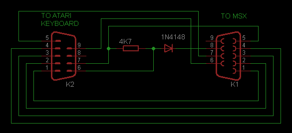
Or in colors, lol!

I have also wrote a "driver" in assembly to perform some tests on an emulator. The code have been optimized in size the most that I could do and now it can read raw key scans from joystick ports 1 and 2.
; PSG IO addresses
PSGAD: EQU 0A0H
PSGWR: EQU 0A1H
PSGRD: EQU 0A2H


ORG 09000h
ld a,(PORTKB)
;
; Scan keyboard connected at Atari Joystick port
;
; Inputs:
;        register A: 0=Connector 1, >0=Connector 2.
ScanKB2600:
   and a ; set zero flag accordingly
   ; Save PSG Context
   ld a,15
   out (PSGAD),a
   in a,(PSGRD)
   ld (SAVPSG),a
   ld hl, KBROWS

   ; Select Joystick port accordingly
   jr NZ, ScanCon2

ScanCon1:
   and 10111111b  ; clear bit 6  (joy port 0)
   or  00010011b  ; set bits 4, 1, and 0  (all rows unset)
   ld b,a
   ld c,a
   res 4,a         ; row 0 (pin8) low, rows 1 and 2 (6 and 7) high
   res 0,b         ; row 1 (pin6) low, rows 0 and 2 (7 and 8) high
   res 1,c         ; row 2 (pin7) low, rows 0 and 1 (6 and 8) high
   jr ScanRow0

ScanCon2:
   or  01101100b  ; set bits 6, 5, 3, and 2  ( joy port 1, all rows unset)
   ld b,a
   ld c,a
   res 5,a         ; row 0 (pin8) low, rows 1 and 2 (6 and 7) high
   res 2,b         ; row 1 (pin6) low, rows 0 and 2 (7 and 8) high
   res 3,c         ; row 2 (pin7) low, rows 0 and 1 (6 and 8) high

ScanRow0:  ld e,a
   call SaveRow

ScanRow1:  ld e,b
   call SaveRow

ScanRow2:  ld e,c
   call SaveRow

RestorePSG:
   ld e,(hl) ; hl now points to SAVPSG

SaveRow:
   di
   ld a,15
   out (PSGAD),a
   ld a, e
   out (PSGWR),a   ; update register 15
   ld a,14
   out (PSGAD),a   ; select register 14
   in a,(PSGRD)    ; read keys hhhh*741
   or 11110000b   ; mask unused bits
   ld (HL),a   ; save keyboard state
   inc hl
   ei
   ret


; Variables

; keyboard rows hhhh#963, hhhh0852, hhhh*741
KBROWS: EQU 09800h

; PSG register 15 save state (overwritten at the exit)
SAVPSG: EQU 09803h

PORTKB  : EQU 09804h ; 0 -> connector 0, 255 -> connector 1
Discussions
Become a Hackaday.io Member
Create an account to leave a comment. Already have an account? Log In.