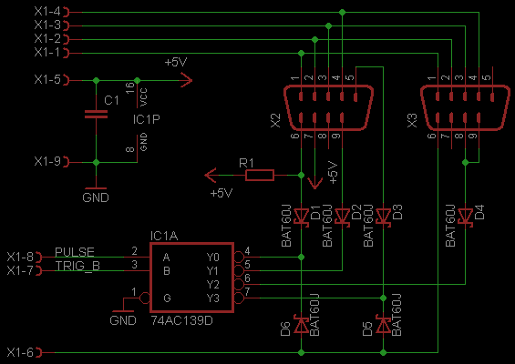
Added a second diode to enhance the detection

And drafted some driver code that provides scan and decode that takes 98 bytes plus 5 RAM addresses.
; Scan Atari keyboard and single button joystick using
; and adapter with 74LS139

; PSG IO addresses
PSGAD: EQU 0A0H
PSGWR: EQU 0A1H
PSGRD: EQU 0A2H

; DetectKB2600 - Detect Atari controller keyboard
; Input:
;       register A: 0=Connector 1, >0=Connector 2.
; Ouptut:
;       Z -> keyboard detected
;      NZ -> keyboard adapter not detected
DetectKB2600:
  call ScanKB2600
  ld de,KBROWS
  ld c,0
Detct0:
  ld a,(de)
  and 00010000b ; isolate bit 4
  rla
  or c
  ld c,a
  inc de
djnz Detct0
  cp 01000000b
  ret

;
; ScanKB2600 - Scan Atari controller keyboard
;
; Inputs:
;        register A: 0=Connector 1, >0=Connector 2.
; Ouptuts   :          bit  7  6  5  4  3  2  1  0
;           KBROWS     ->   1  1  1  0  #  9  6  3
;           KBROWS + 1 ->   1  1  1  1  0  8  5  2
;           KBROWS + 2 ->   1  1  1  0  *  7  4  1
;(JOYTBITS) KBROWS + 3 ->   1  1  1  TA RG LF DW UP

ScanKB2600:
   ; set zero flag according to port option
   and a
   ; Save PSG Context
   ld a,15
   out (PSGAD),a
   in a,(PSGRD)
   ld (SAVPSG),a
   ld hl, KBROWS

   ; Select Joystick port accordingly
   jr NZ, ScanCon2

ScanCon1:
   and 10101101b  ; clear bit 6 -> Joysel -> joy port 0, 4:PULSE and 1:TRIGGER B
;  a = pins 8,7 low  (row 0)
   ld b,a  ; a = pin 8=0, pin 7=0 (row 0)
   set 4,b ; b = pin 8=1, pin 7=0 (row 1)
   ld c,b  ;
   set 1,c ; c = pin 8=1, pin 7=1 (row 2)
   ld d,a  ; a = pin 8=0, pin 7=0 (row 0)
   set 1,d ; b = pin 8=0, pin 7=1 (Joystick)

   jr ScanRow0

ScanCon2:

   and 10010111b  ; clear bit 5:PULSE and 3:TRIGGER B
   set 6,a        ; Set bit 6 -> Joysel -> joy port 1
   ld b,a  ; a = pin 8=0, pin 7=0 (row 0)
   set 5,b ; b = pin 8=1, pin 7=0 (row 1)
   ld c,b  ;
   set 3,c ; c = pin 8=1, pin 7=1 (row 2)
   ld d,a  ; a = pin 8=0, pin 7=0 (row 0)
   set 3,d ; b = pin 8=0, pin 7=1 (Joystick)

ScanRow0:
   ld e,a
   call SaveRow

ScanRow1:
   ld e,b
   call SaveRow

ScanRow2:
   ld e,c
   call SaveRow

ScanJoy:
   ld e,d
   call SaveRow

RestorePSG:
   ld e,(hl) ; hl now points to SAVPSG

SaveRow:
   di             ; disable interrupts
   ld a,15
   out (PSGAD),a
   ld a, e
   out (PSGWR),a  ; update register 15
   ld a,14
   out (PSGAD),a  ; select register 14
   in a,(PSGRD)   ; read keys hhhh*741
   or 11110000b   ; mask unused bits
   ld (HL),a      ; save keyboard state
   inc hl
   ei
   ret

 ; Variables
; keyboard rows HHHL#963, HHHH0852, HHHL*741
 KBROWS:  DS 3
 JOYBITS: DS 1
;   PSG register 15 save state during execution, destroyed buttons at the end
; must be contiguous to Joybits
 SAVPSG: DS 1
 danjovic
Discussions
Become a Hackaday.io Member
Create an account to leave a comment. Already have an account? Log In.