The accuracy of reflectograms, the reliability of the conclusions made, and the time spent on diagnostics largely depend on the set of additional functions of a particular device.
A modern reflectometer must meet the following requirements:
• have a decent amount of memory for storing reflectograms with workable resolution;
• be able to exchange data with a computer;
• have two channels for comparison and differential mode support;
• automatically calculate the return loss value.
Other useful features that make the operator’s job easier, thus worth mentioning:
• automatic search for defects when viewing a reflectogram;
• automatic two-dimensional scale adjustment to fit the most significant defect found;
• distance measurement between two points or cursor positions on the reflectogram;
• registering transient or "non-persistent" faults.
Introduced as another means to simplify the operation, some of the functions mentioned above had a revolutionary impact on fault localization techniques using reflectometers. So they are worth a closer look.
Saving reflectograms to memory
Thanks to this feature, measurements themselves do not require any specific knowledge, and qualified specialists can analyze the results later. Suppose the initial cable parameters were set incorrectly. In that case, the needed information can always be clarified, and using the saved data, the results can be reprocessed without going back to the site.
Data uploading to and downloading from a PC
Uploading data to the cloud or to a computer provides the possibility of archiving and further processing. For example, reflectogram files can be viewed, printed, scaled, compared, superimposed on each other or on a trace diagram, sent, etc. Reflectograms can be processed using proprietary (supplied by the manufacturer) and open (particularly graphic editors) programs. If necessary, files can be sent for analysis to a more experienced specialist. A critical point should be made: the reflectogram file can be loaded back into the reflectometer’s memory, for example, for comparison with a new reflectogram at the diagnostic site.
Dual channel
Two measuring paths allow one to take reflectograms simultaneously from two pairs and display them for visual comparison. Some devices also implement further processing of the received reflectograms.
Comparison and differential modes
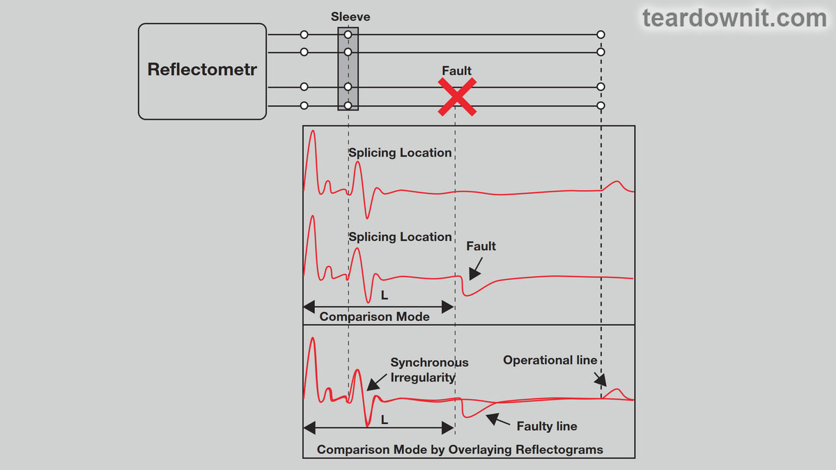
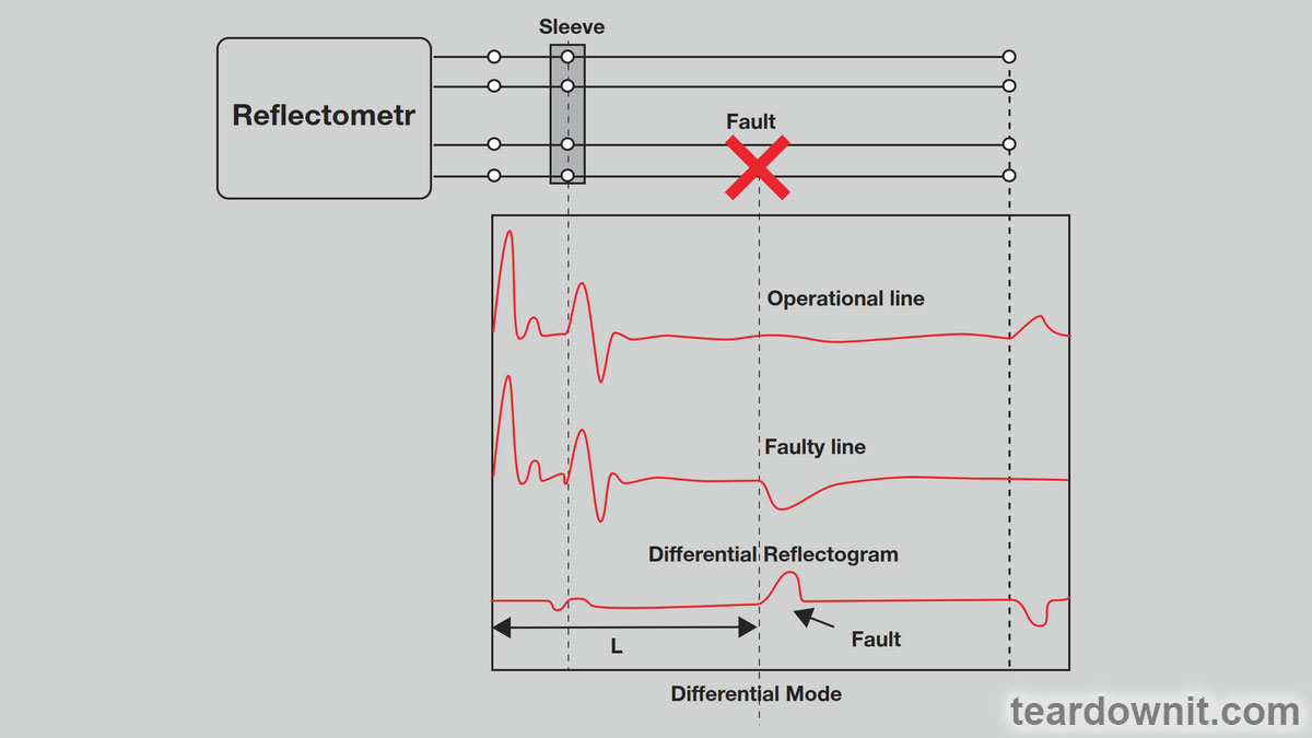
These two modes greatly simplify the localization of the main fault against the background of numerous synchronous interferences (repeating reflections from the input of the device, reflections from couplings, inserts, branches, etc.). The amplitude of the signal reflected from the main fault in the line could be less than the amplitude of these interferences. Suppose one receives signals from both faulty and serviceable pairs of the same cable. In that case, their overlay (comparison mode) or subtraction (differential mode) will allow one to identify differing sections of the reflectogram, i.e., exactly those places in the characteristic where the faulty pair does not coincide with the working one and where the defect is probably located.

Differential mode is more convenient—the reflectograms of the damaged and good pairs are subtracted, which leads to compensation for almost all synchronous interference. It is much easier to identify differences this way than by eyeballing them. Using this mode, damage locations are clearly visible on the difference reflectogram.
If the device is dual-channel, both reflectograms can be obtained in real-time. Such devices are simply irreplaceable for localizing places where pairs have been damaged due to improper connection of wires (decoupling).

In devices with built-in memory, comparison and differential modes are implemented using reflectograms obtained in real-time from two different channels of the device or by processing saved reflectograms created as a result of the last measurement and stored in the device’s memory. The latter mode provided a revolutionary ability to diagnose a cable by comparing two reflectograms from one trace—a currently obtained "new" one and a preliminary saved "old" one.
AUTOMATIC RETURN LOSS CALCULATION FUNCTION
Any damage to the cable leads to a change in impedance, and any change in impedance shows itself in the reflectogram. The amplitude of the reflected signal depends on the degree of impedance change and the distance to the spot of the change occurrence (both the pulse and the reflected signal are attenuated as they propagate along the cable). This fact significantly complicates fault localization. The pulse reflected from the defect will have a lower amplitude on the reflectogram (if the defect is located far from the reflectometer) than signals from other insignificant but closely located inhomogeneities (for example, cable splice points).
A special parameter has been introduced to assess the defect's size: return loss. With its help, one can compare the contributions of various irregularities and find the main one.
The mathematical formula for calculating return loss is as follows:
RL = 20 log10(Vo/Vr), where RL is return loss expressed in decibels (dBRL); Vo is the signal voltage at the reflectometer output; and Vr is the voltage of the reflected signal.
When the signal reaches a point of impedance change, some (or all) of its energy is reflected back to the device. By calculating the value of return loss for a given area using the above formula, one can estimate the amount of energy being reflected from this area and, therefore, compare the contribution of the inhomogeneities of the location.
To avoid confusion, it is worth remembering that small return loss values indicate that a significant part of the pulse energy is reflected at the point of the cable defect (i.e., return loss is small). The higher the return loss value, the weaker the defect, and vice versa. All the energy of the emitted pulse is reflected from the most significant defects, like a break or a shortage; the return loss, in this case, is zero.
Based on the change in return loss over time, it is possible to evaluate the change in the state of the cable line at the places where cable sections are spliced. If, for a section with a certain coupling, a value of 40 dBRL was obtained last year, and this year it is 33 dBRL, then the conclusion is obvious: the connection is degrading.

It is worth noting that the value of return loss measured in the area between the reflectometer and the defect is also affected by the distance from the device to the location of the fault in the cable since the cable itself introduces a specific attenuation. For example, if you are 100 feet away from a fault estimated to be 20 dBRL, the OTDR will show a value of 25 dBRL. If you are 500 feet away from the damage, the device will record 35 dBRL. For this reason, it is advised to be as close to the damage point as possible.
Return loss can be calculated from the reflectogram, but such techniques are difficult to master. That is why automatic return loss calculation dramatically simplifies the operator's life. Now, he can quickly use qualitative information (reflectogram) and quantitative information to localize a defect. Some reflectometers calculate return loss in the area between two cursors, which allows for an additional comparison of the magnitudes of any two abnormalities.
 teardownit
Discussions
Become a Hackaday.io Member
Create an account to leave a comment. Already have an account? Log In.