 Jesse Farrell
History
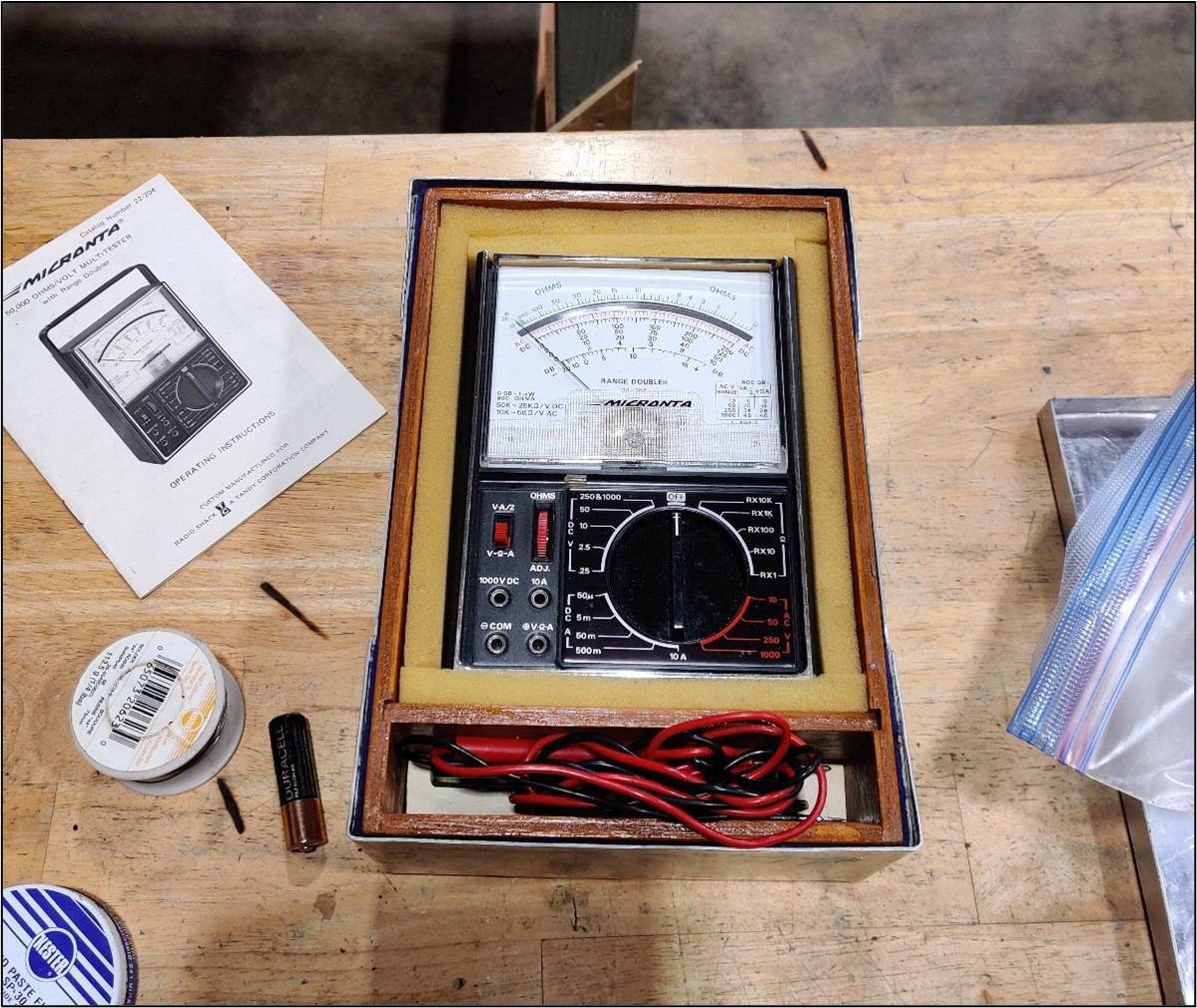
I was pretty excited to be handed my dad’s old multimeter. Tandy!? Radio shack? What are these strange words… I was born in the wrong generation to experience these things first hand, so I was pretty excited to have some genuine Tandy equipment on my bench.
During the multimeter handoff, I was told it might be broken (EVEN BETTER!). We tried turning the device on, and sure enough there was no response… But who can blame the poor thing, its been living in a barn for the past 15+ years.
Schematic
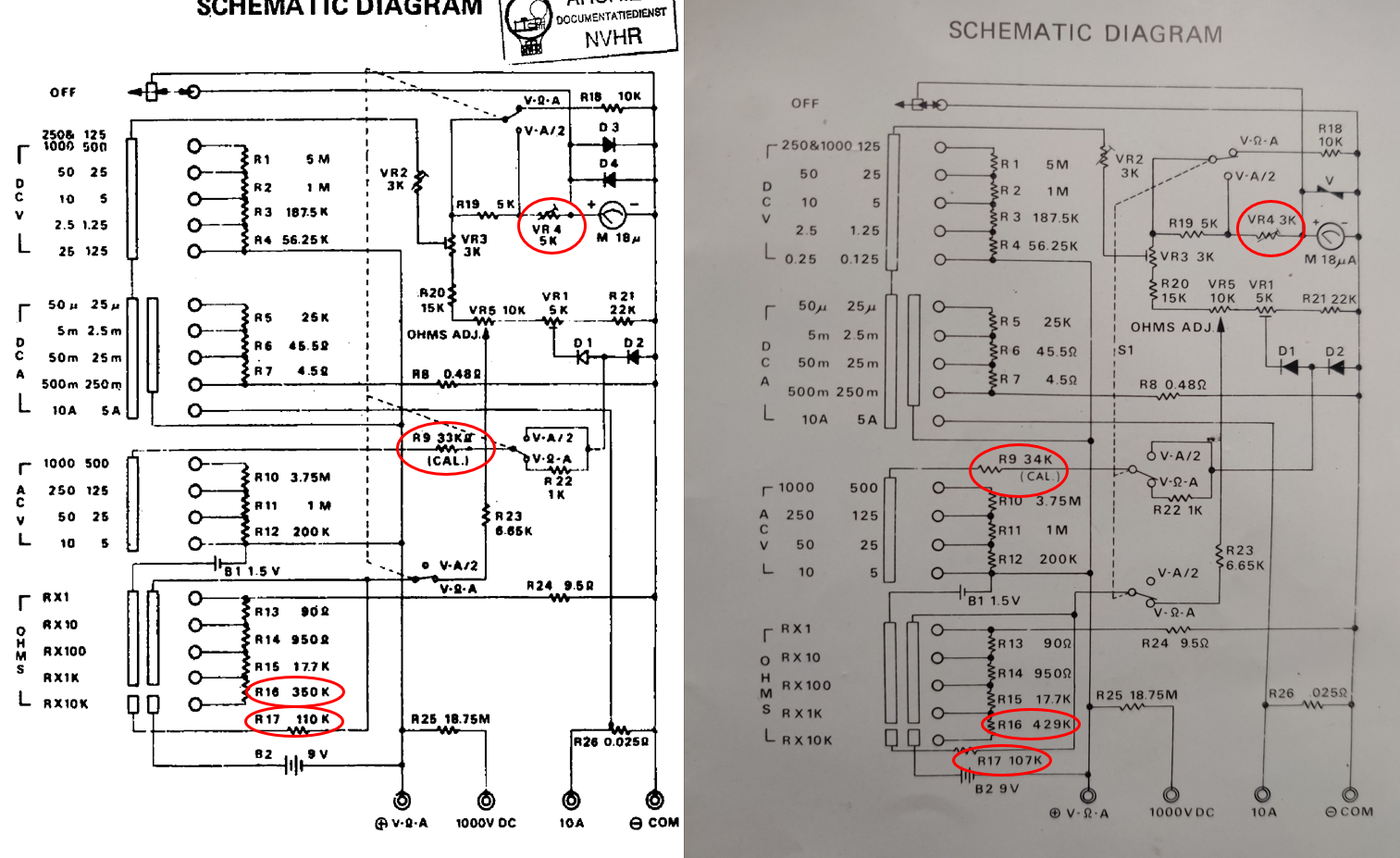
Luckily this multimeter still has its manual with it, but I know not everyone’s that lucky. Here’s the schematic for “Micronta 50,000 OHMS/VOLT MULTITESTER with Range Doubler”, catalog number 22-204.
My schematic looks different from what I found online, specifically R16, R17, R9, VR4. But I suspect, its just a variant of this product. Maybe this schematic will help someone else get out of a rabbit hole. On the right is my schematic, and on the left is theoretically the same schematic found on the web.
Issue #1 – Battery Terminals
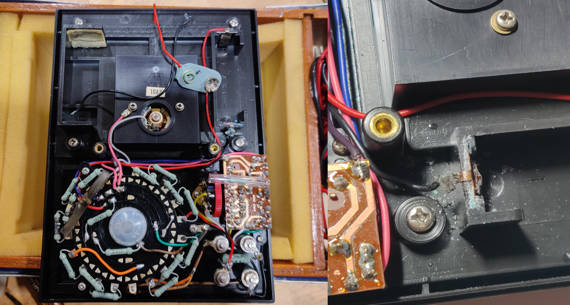
Removing the backplate revealed some nasty corrosion on the mismatched batteries. At first the 9V didn’t look too bad, but when I tried removing it, the cable just “let go” of its solder joint. When I finally pulled the 9V free from its plug, it broke the terminals! I’ll probably try to replace/resolder the 1.5V connector. The aftermath is shown below.
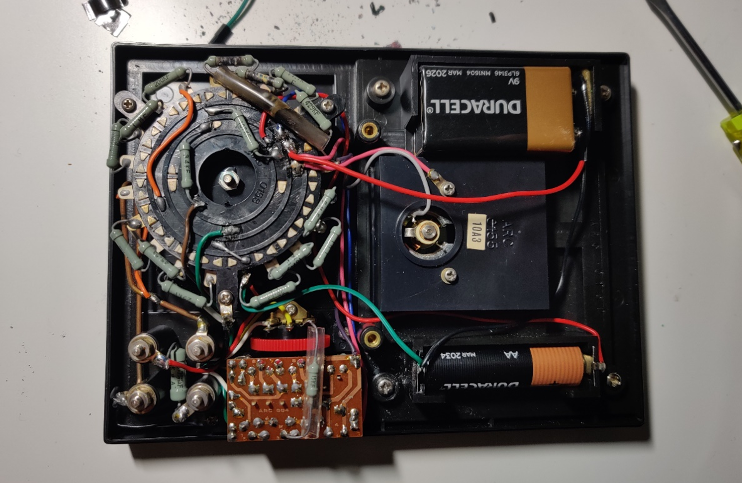
Luckily, I have some extra battery connectors in my parts bin. I replaced both terminals, and plugged in new batteries. Onto the next issue!
Issue #2 – Burnt Resistors
You’ve probably noticed a couple burned parts on the pictures I’ve shown above. It looks like someone tried to measure something with some “umph” while set to measure resistance (specifically 100x). As a result (likely mains voltage) punched its way through R14, R13 and R24.

I had some spare parts to replace these resistors, but it’s a bit of a downgrade. Note, I’m not worried about the performance after my repair… I have two DMM on my bench, this is just a repair for repairs sake. I replaced R14 with ¼ watt 270+680, and R13 with ¼ watt 22+68. For R24 I had to use 3x resistors in parallel (22.1//22.1//67.9). All resistors were verified on a Fluke 87V.
After soldering in the new parts, all is working!
Shown below is a 22ohm resistor being measured. Looks good enough. I also verified the other ranges, as well as the voltage reading. I deem this repaired.

Discussions
Become a Hackaday.io Member
Create an account to leave a comment. Already have an account? Log In.