This article is about a simple transistor power amplifier.
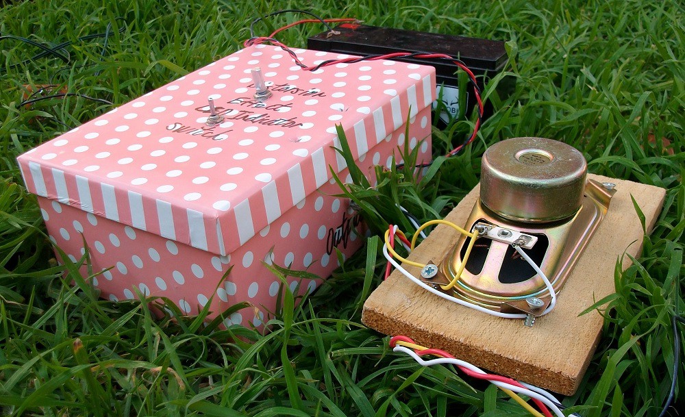
Figure 1: Device.
You can see how my circuit works in this video:
Step 1: Design the Circuit
I have drawn the circuit via PSpice software:

Figure 2: Design the Circuit.
The optional capacitor low pass filter circuit is useful when the amplifier is connected to mains powered 8 V power supply. The two 10 mF capacitors are needed to filter the possible 60 Hz or 50 Hz ripple. You do not need this circuit if the amplifier is battery-powered.
I have chosen two 10,000 uF capacitors for low pass frequency of:
Flp1 = 1 / (2 * pi * (2 * Cs1a) * (Rs1a / 2))
= 1 / (2 * pi * (2 * 10 mF) * (4.7 ohms / 2))
= 3.3863 Hz
The maximum current across the Cs1a and Cs1b capacitors is when the voltage across the capacitors is zero:
IcsMax = Vs / (Rs1a / 2) / 2
(divide by 2 because there are two capacitors)
The maximum voltage is 12 V.
= 12 V / (4.7 ohms / 2) / 2
= 2.5532 Amps
The maximum power is at half supply voltage:
PcsMax = VcsHalfSupply * IcsHalfSupply / 2
(divide by 2 because there are two capacitors)
= (Vs / 2) * ((Vs / 2) / (Rs1a / 2)) / 2
= 7.6596 Watts
Calculate the low pass frequency of the second power supply low pass filter:
Flp2 = 1 / (2 * pi * (3 * Cs2a) * (Rs2a / 2))
= 1 / (2 * pi * (3 * 470 uF) * (100 ohms / 2))
= 2.2575 Hz
The average current across the LEDs equals to:
Iled = (Vs - 2 * Vled) / (Rd1 + Rd2)
= (12 V - 2 * 2 V) / (470 ohms + 470 ohms)
= 8 V / 940
= 8.5106 mA
The maximum current across the LED is equal to:
Iled = (Vs - Vled - Vbe) / Rd1
= (12 V - 2 V - 0.7 V) / 470 ohms
= 19.7872 mA
The 1 Meg potentiometer allows a clipping sound effect.
Step 2: Simulations
Time Domain:
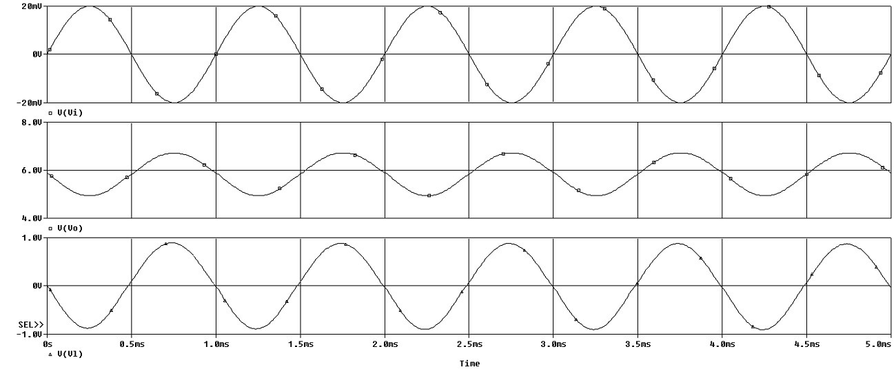
Figure 3: Simulations Transient.
Frequency:
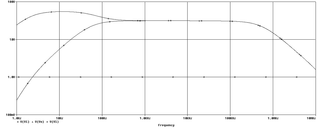
Figure 4: Simulations Frequency.
Step 3: Make the Circuit
I made the circuit on a small matrix board:
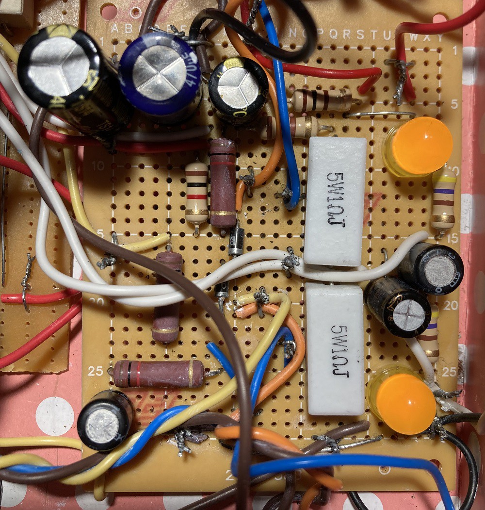
Figure 5: Make the Circuit.
Step 4: Encasement
I used a cheap $2 gift box to save money:
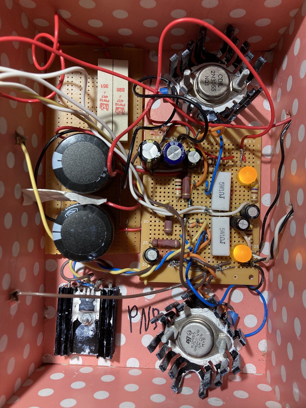
Figure 6: Encasement.
I used big 10 mF capacitors and 10-watt 4.7 ohms resistors because I connected the circuit to a 12 V battery.
Step 5: Testing
I used a Hantek 6022BE USB Oscilloscope to test my circuit.
The yellow plot is the input and the green plot is the output.
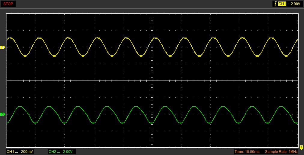
Figure 7: Testing 100 Hz Sine Wave Input.
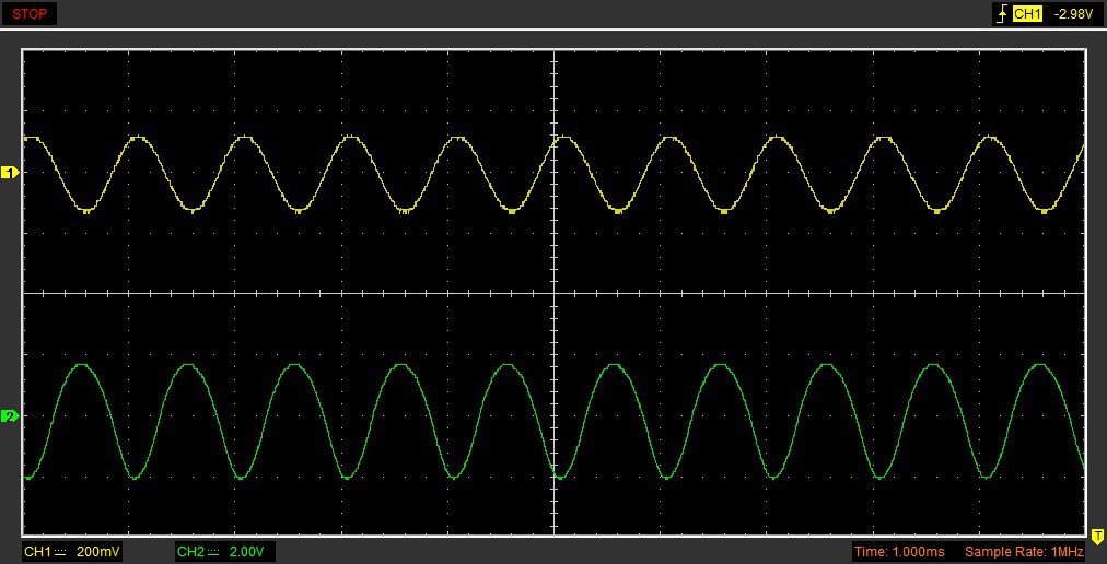
Figure 8: Testing 1 kHz Sine Wave Input.
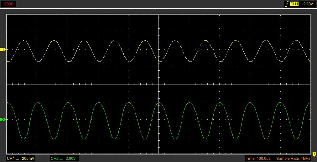
Figure 9: Testing 10 kHz Sine Wave Input.
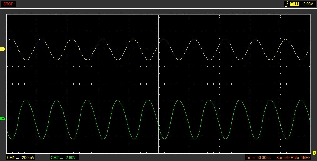
Figure 10: Testing 20 kHz Sine Wave Input.
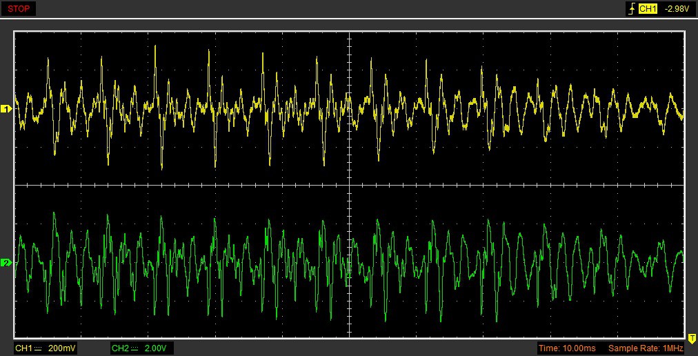
Figure 11: Testing Voice Input.
Talking:
Conclusion
The circuit can be produced without a 1 Megohm potentiometer and without the LEDs if you bias the output transistor emitters at half supply voltage.
 Product Circuits
Discussions
Become a Hackaday.io Member
Create an account to leave a comment. Already have an account? Log In.