 Product Circuits
-
Transistor Power Amplifier
11/04/2024 at 04:36 • 0 commentsThis article is about a simple transistor power amplifier.
![]()
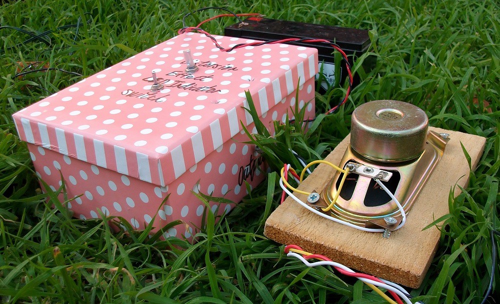
Figure 1: Device.
You can see how my circuit works in this video:
Step 1: Design the Circuit
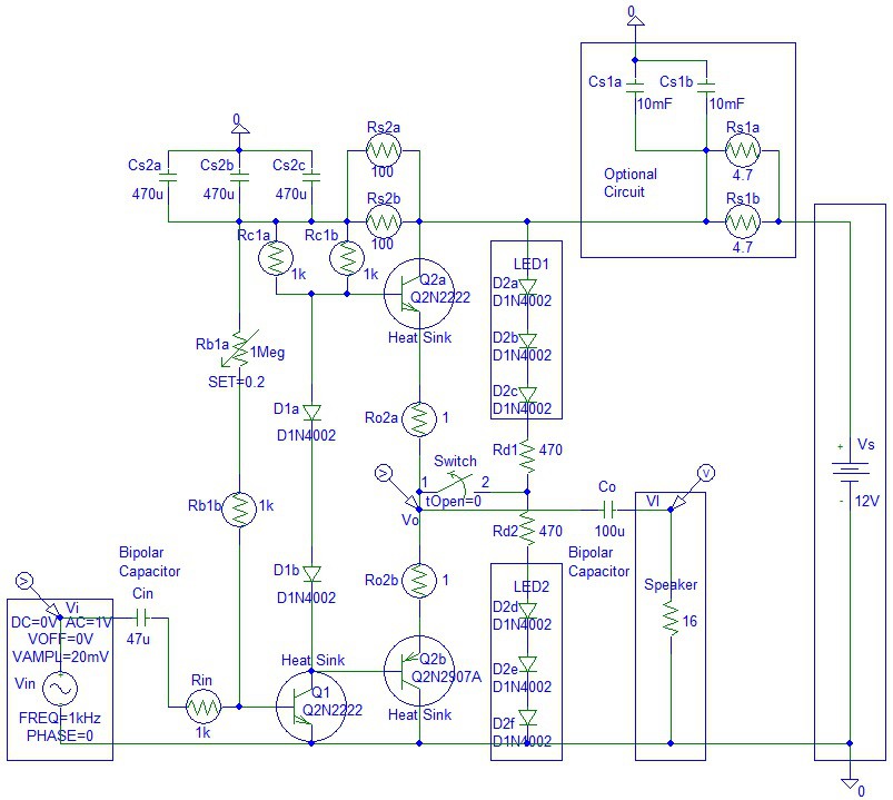
I have drawn the circuit via PSpice software:
![]()
Figure 2: Design the Circuit.
The optional capacitor low pass filter circuit is useful when the amplifier is connected to mains powered 8 V power supply. The two 10 mF capacitors are needed to filter the possible 60 Hz or 50 Hz ripple. You do not need this circuit if the amplifier is battery-powered.
I have chosen two 10,000 uF capacitors for low pass frequency of:
Flp1 = 1 / (2 * pi * (2 * Cs1a) * (Rs1a / 2))
= 1 / (2 * pi * (2 * 10 mF) * (4.7 ohms / 2))
= 3.3863 Hz
The maximum current across the Cs1a and Cs1b capacitors is when the voltage across the capacitors is zero:
IcsMax = Vs / (Rs1a / 2) / 2
(divide by 2 because there are two capacitors)
The maximum voltage is 12 V.
= 12 V / (4.7 ohms / 2) / 2
= 2.5532 Amps
The maximum power is at half supply voltage:
PcsMax = VcsHalfSupply * IcsHalfSupply / 2
(divide by 2 because there are two capacitors)
= (Vs / 2) * ((Vs / 2) / (Rs1a / 2)) / 2
= 7.6596 Watts
Calculate the low pass frequency of the second power supply low pass filter:
Flp2 = 1 / (2 * pi * (3 * Cs2a) * (Rs2a / 2))
= 1 / (2 * pi * (3 * 470 uF) * (100 ohms / 2))
= 2.2575 Hz
The average current across the LEDs equals to:
Iled = (Vs - 2 * Vled) / (Rd1 + Rd2)
= (12 V - 2 * 2 V) / (470 ohms + 470 ohms)
= 8 V / 940
= 8.5106 mA
The maximum current across the LED is equal to:
Iled = (Vs - Vled - Vbe) / Rd1
= (12 V - 2 V - 0.7 V) / 470 ohms
= 19.7872 mA
The 1 Meg potentiometer allows a clipping sound effect.
Step 2: Simulations
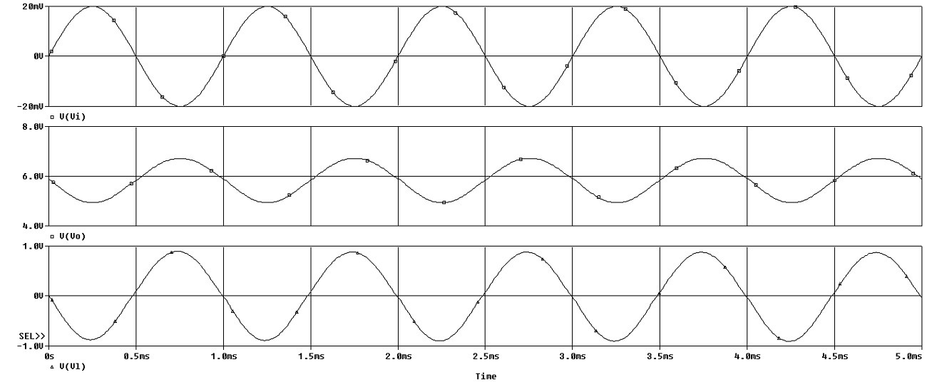
Time Domain:
![]()
Figure 3: Simulations Transient.
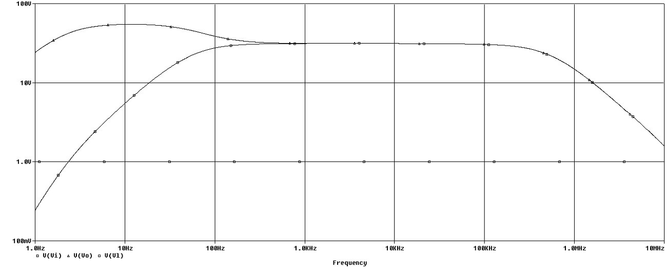
Frequency:
![]()
Figure 4: Simulations Frequency.
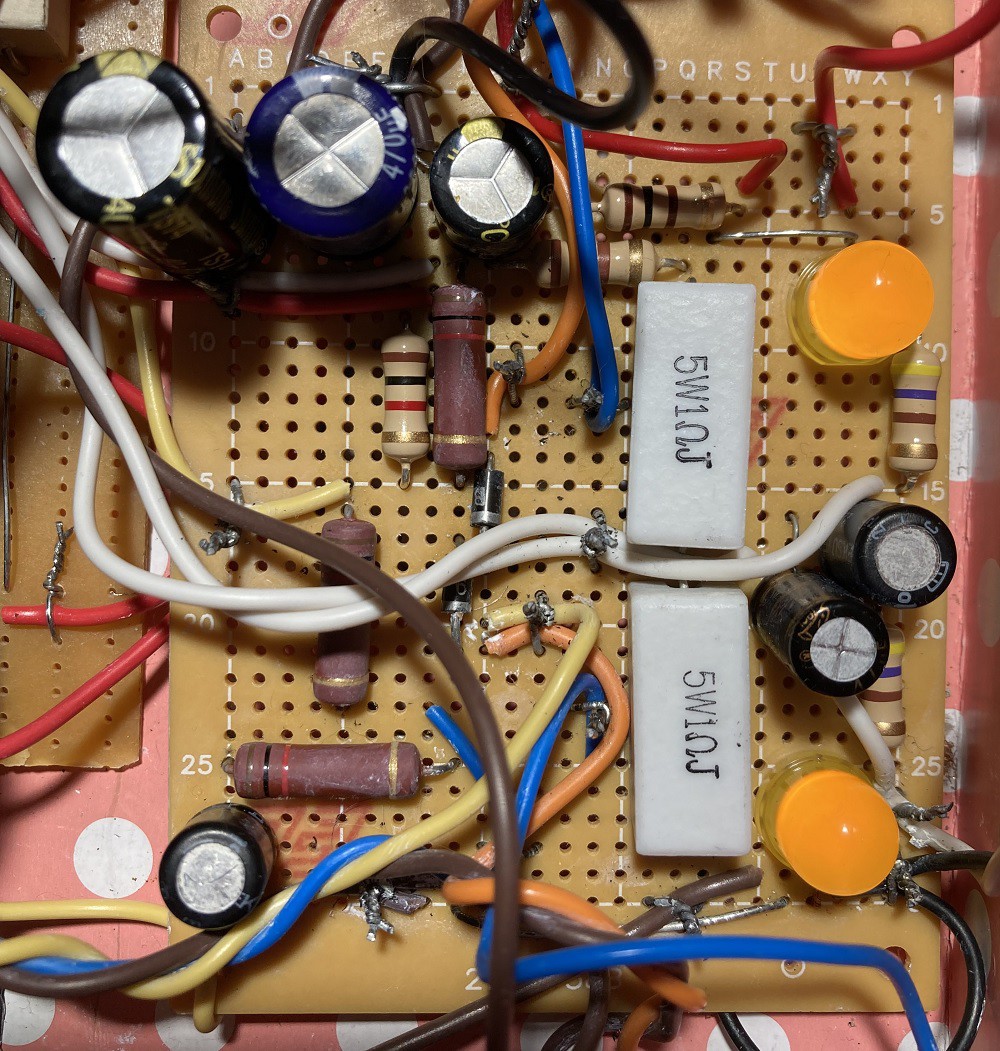
Step 3: Make the Circuit
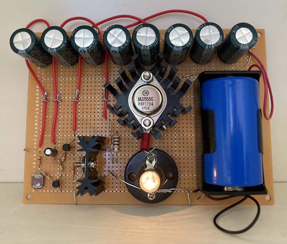
I made the circuit on a small matrix board:
![]()
Figure 5: Make the Circuit.
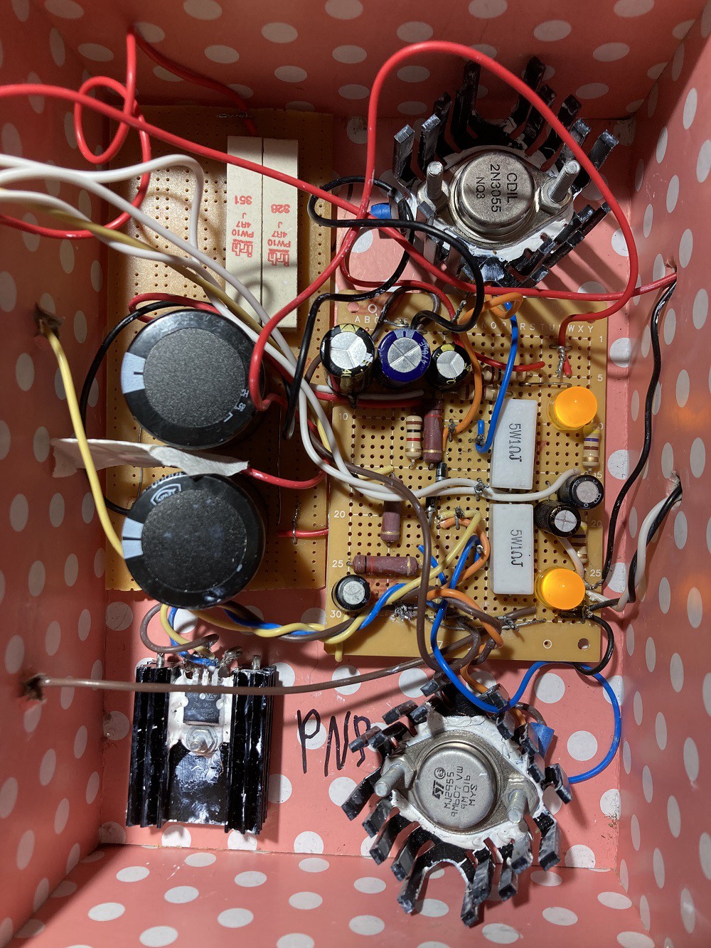
Step 4: Encasement
I used a cheap $2 gift box to save money:
![]()
Figure 6: Encasement.
I used big 10 mF capacitors and 10-watt 4.7 ohms resistors because I connected the circuit to a 12 V battery.
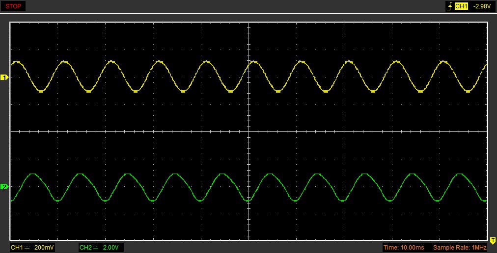
Step 5: Testing
I used a Hantek 6022BE USB Oscilloscope to test my circuit.
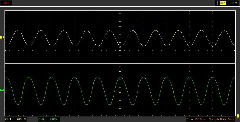
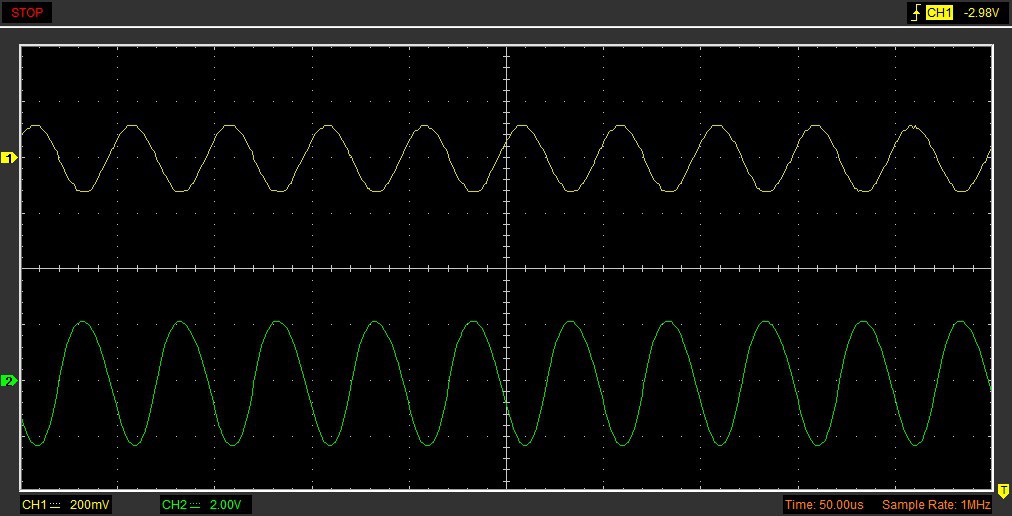
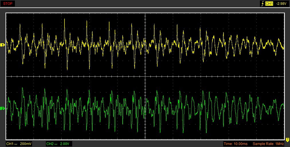
The yellow plot is the input and the green plot is the output.
![]()
Figure 7: Testing 100 Hz Sine Wave Input.
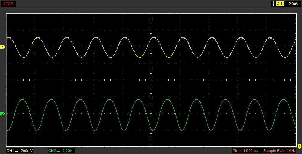
![]()
Figure 8: Testing 1 kHz Sine Wave Input.
![]()
Figure 9: Testing 10 kHz Sine Wave Input.
![]()
Figure 10: Testing 20 kHz Sine Wave Input.
![]()
Figure 11: Testing Voice Input.
Talking:
Conclusion
The circuit can be produced without a 1 Megohm potentiometer and without the LEDs if you bias the output transistor emitters at half supply voltage.
-
LM311 Touch Buzzer
06/19/2024 at 07:51 • 0 commentsThis article is about LM311 comparator IC (integrated circuit) touch buzzer circuit:
![]()
You can see the circuit working in this video:
Step 1: Design the Circuit
I have drawn the circuit in PSpice version 9.1 student edition:
![]()
The output of LM311 comparator is an NPN transistor collector. The current in pin 7 starts flowing when the positive input (pin 2) is below the negative input (pin 3). The output is inverted because the output of the comparator is an inverter logic gate.
Comparator is designed to drive coils. A buzzer coil turns ON and OFF similarly to a relay turning ON and OFF. The current in the coil continues to flow in the same direction when the current to the coil is discontinued. This is why I connected the diode.
The buzzer current is 40 mA. The 9 V battery can supply a current of 100 mA. The remaining 60 mA current is for the comparator IC (integrated circuit) and the resistor circuits.
The circuit will work without the 10 Megohm resistor. However, it is bad practice to leave pin 2 disconnected.
Step 2: Simulations
Simulations show that when the human resistance falls before about 8 Megohms high current begins to flow.
![]()
Step 3: Make the Circuit
I used a wire wrap socket and wire wrap tool to connect the circuit. I tried Rtouch resistor of 1 Megohms, 4.7 Megohms. However, the circuit was not turning ON well with those resistors (1 Megohm and 4.7 Megohm) when compared to Rtouch of 10 Megohms.
![]()
Conclusion
This circuit is useful for toy applications.
-
Emergency Lights
11/02/2020 at 02:59 • 0 commentsThis article shows the emergency lights system.
![]()
The circuit turns the light bulb ON when the lights are turned OFF and keeps the light bulb ON for a few seconds even after the lights are back ON. This is to make sure the circuit works appropriately if the room lights are blinking.
You can see the circuit working in this video:
Step 1: Design the Circuit
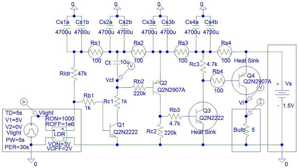
I have drawn the circuit in PSpice simulation software, student edition version 9.1:
![]()
The Vlight pulse waveform represents the presence of light in the room (5 V when lights are ON and 0 V in darkness, when lights are OFF). The LDR (Light Dependent Resistor) voltage-controlled switch changes resistance from 1 kohm to 1 Megohm when the lights are turned OFF.
I used Rldr as high as 47k to ensure that the light bulb remains off and stays off unless the sensor is exposed to complete darkness. This is to prevent wasting battery power. However, the Rldr resistor is low enough to ensure that the Ct capacitor charges very quickly when the lights are OFF. I used a big light-dependent resistor that has a small resistance, thus allowing me to use a relatively small Rldr value. This is why I did not use a cheap photodiode.
The switching action of LDR propagates through the four transistors from Q1 to Q4 to turn ON the light bulb. I connected Rc2 and Rc3 to ensure that the transistors are not disconnected when the light bulb is OFF.
By making a few approximations, we can estimate the minimum required current gains (Beta parameters) for each transistor for the circuit to work:
Beta4 = Ibulb / ((Vs - Vbe4 - Vcesat3) / Rb4)
Beta3 = ((Vs - Vbe4 - Vcesat3) / Rb4) / ((Vs - Vbe3 - Vcesat2) / Rb3)
Beta2 = ((Vs - Vbe3 - Vcesat2) / Rb3) / ((Vs - Vbe2 - Vcesat1) / Rb2)
Beta1 = ((Vs - Vbe2 - Vcesat1) / Rb2) / ((Vs - Vbe1) / Rldr);
We enter the equations into the Matlab file:
clear all;close all
Ibulb=0.3;
Vs=1.5;
Rb4=100;
Rb3=4700;
Rb2=220000;
Rldr=47000;
Vbe1=0.7;
Vbe2=0.7;
Vbe3=0.7;
Vbe4=0.7;
Vcesat1=0.2;
Vcesat2=0.2;
Vcesat3=0.2;Beta4 = Ibulb / ((Vs - Vbe4 - Vcesat3) / Rb4);
disp(['Beta4 = ' num2str(Beta4)])
Beta3 = ((Vs-Vbe4-Vcesat3)/Rb4)/((Vs-Vbe3-Vcesat2)/Rb3);
disp(['Beta3 = ' num2str(Beta3)])
Beta2 = ((Vs-Vbe3-Vcesat2)/Rb3)/((Vs-Vbe2-Vcesat1)/Rb2);
disp(['Beta2 = ' num2str(Beta2)])
Beta1 = ((Vs-Vbe2-Vcesat1)/Rb2)/((Vs-Vbe1)/Rldr);
disp(['Beta1 = ' num2str(Beta1)])
If you do not want to pay for Matlab you can use the free Octave software to obtain the following output:
Beta4 = 50
Beta3 = 47
Beta2 = 46.8085
Beta1 = 0.16023The required current gain (Beta value) for Q1 is very small.
Q3 and Q4 should be power transistors. I used PSpice student edition simulation software, which does not include power transistor components.
The circuit I designed is capable of driving high-current light bulbs. You can use fewer transistors when connecting a bright LED instead of a light bulb because LEDs consume less current than light bulbs. However, the LED will need at least 2 V to work, unlike the light bulb that needs only 1.5 V.
I modelled the light bulb as a 5 ohm resistor because the current across the light bulb is 0.3 Amps. 1.5 V / 0.3 Amps = 5 ohms.
The big 4,700 uF capacitors are used to prevent power supply oscillations due to power supply surges that occur when the light bulb is turned ON or OFF.
Step 2: Simulations
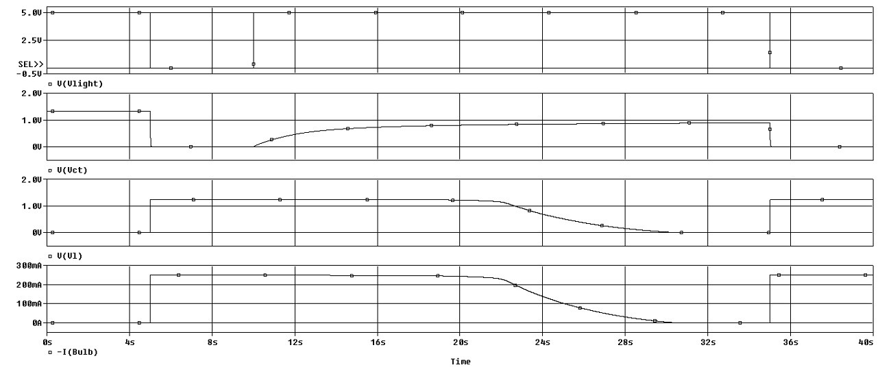
Simulations show that the light bulb turns ON very quickly after the lights are turned OFF and remains fully ON for about 15 seconds after the lights are ON.
![]()
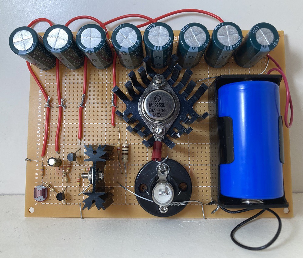
Step 3: Make the Circuit
I soldered the components with lead-free solder and with the use of a 60 W soldering iron:
![]()
Step 4: Testing
I tried testing the response of the LDR sensor by putting my hand on top of the sensor.
Discussion
My circuit allows the driving of higher current LED lights or 1.5 V light bulbs. To drive high-current LEDs or 6 V or 12 V light bulbs, you need to increase the power supply voltage and connect the appropriate...
Read more »
This user joined on 11/02/2020.


 Lutetium
 Benjamin Prescher
 Ian Norton
 dev-lab
 1BarConnection
 metehanemlik
 Jithin Sanal
 shamylmansoor
 Daan Pape
 Clay Graham
 Craig Colvin
 loszelos
 Jimmy Patrick
 Sean Wagoner
 EsoreDre
 Mike Rigsby