 Charlie Theobald
I've watched Eurovision every year for the past 10 years or so - this is probably the first time in the contest's history that an analog synth designer has performed on stage. A little disappointed that crazy British synth man didn't do so well this year, but it's been nice to hear murmurs of synths and vintage electronics in the news and I hope it's inspired some people.
This week
This week has been less productive than I thought it'd be, as I've found most of my time being consumed by our university group project.
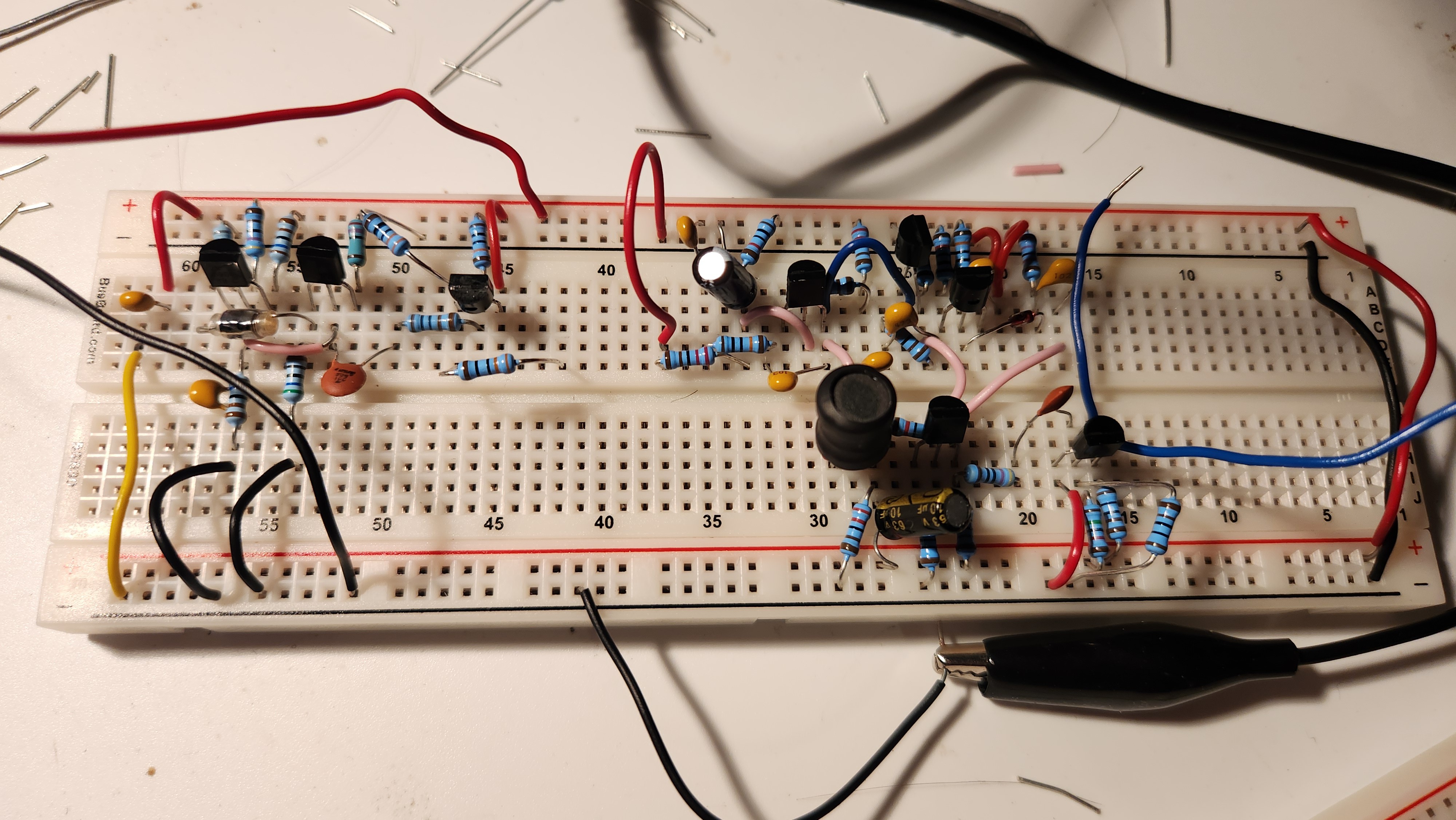
I've still been able to work for a couple of hours each evening at home, and have been focusing on breadboarding both the Korg Lambda and Roland RS-505 Paraphonic master clock generators, and building up the MIDI to CV converter which will become a significant point of focus over the next few weeks.
Many pictures this week and less theory :)
So...which VCO is better?
My main concern in last week's update was the compromise between the large rise-time caused by the Lambda's first-order feedback, and the possible increased parasitics of the Paraphonic's second-order feedback.
I had a suspicion that the Paraphonic's master VCO would be better performing, as the Lambda was designed as a budget synthesizer at the time of its release, but also questioned whether first-order feedback could be a better design choice. Over the past week, I've examined both circuits with the oscilloscope to get a real-world comparison, and the results are worth analysing.
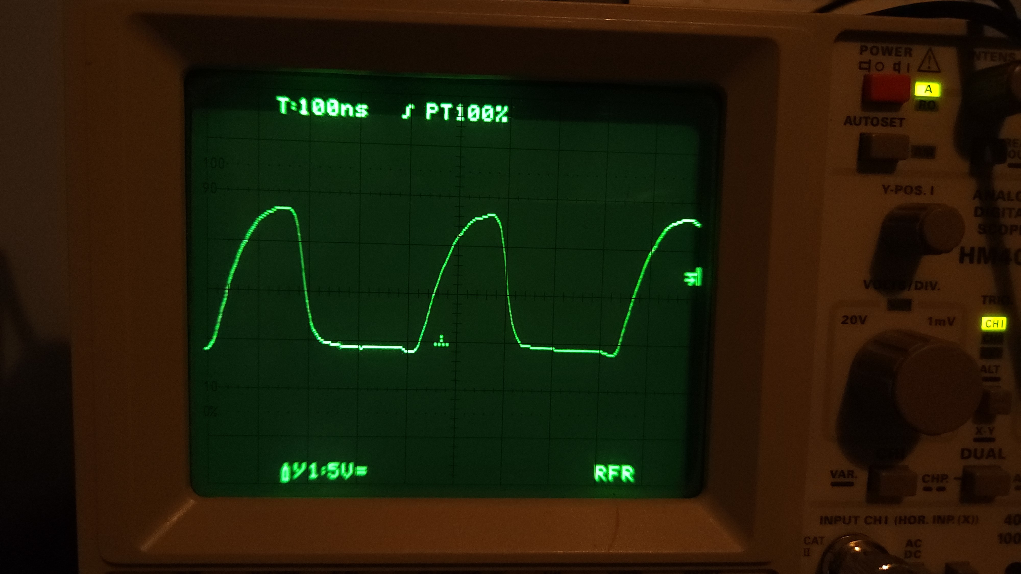
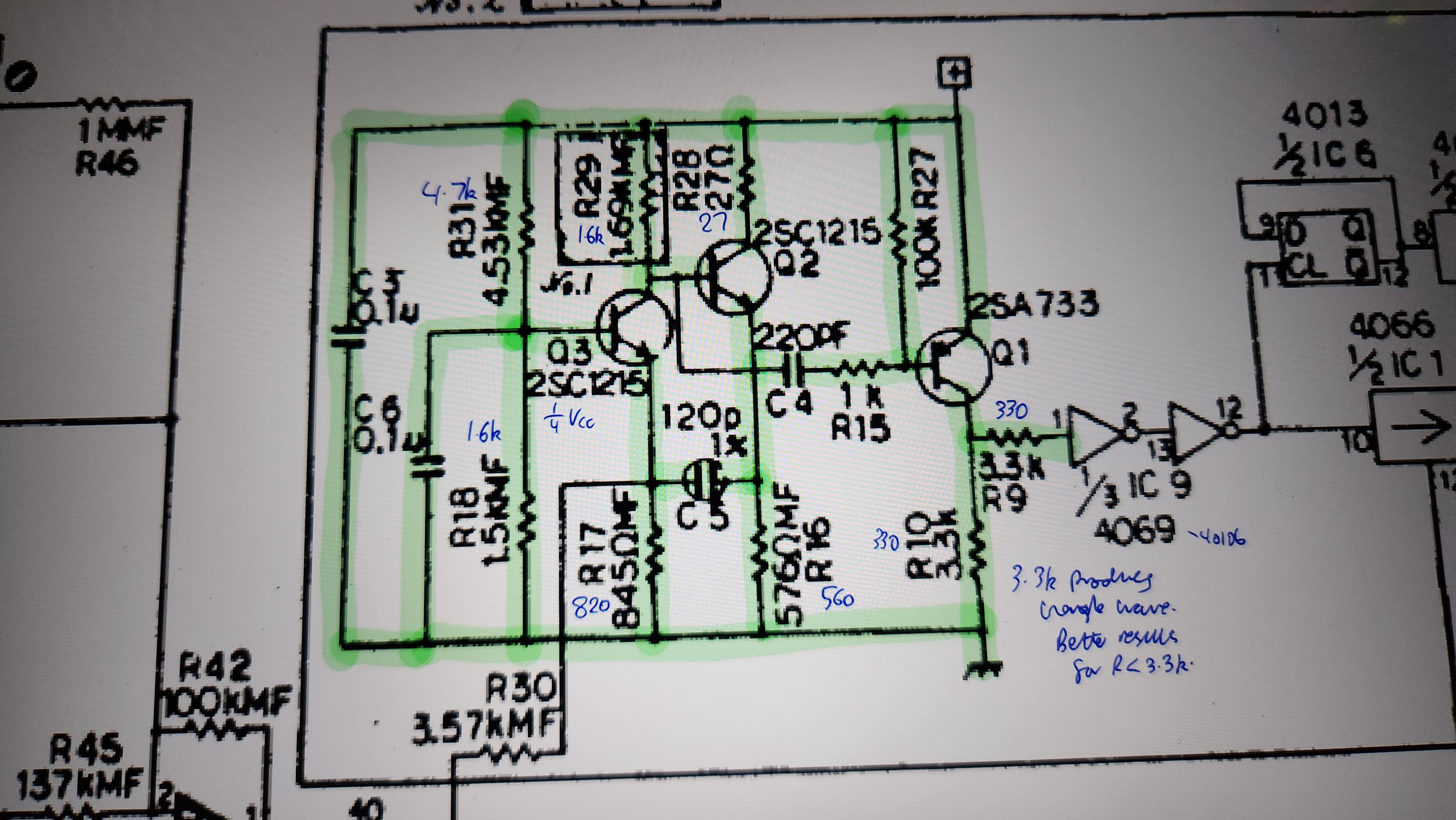
This is the output of the Lambda's master VCO. The first-order charging and discharging of the 120pF capacitor is very obvious on the waveform, and the rise-time is close to our estimate, at around 120ns by inspection. Interestingly, I found that when the output resistors R9/R10 were left at 3.3kΩ, the output appeared more like a low-amplitude triangle wave. Therefore, I decreased R9/R10 by a factor of 10 to 330Ω, increasing the quiescent output voltage of Q1, and this seemed to do the job. I still need to play around with different values of R9/R10 that give the best results.
This VCO really impressed me with its fantastic frequency stability. Despite having a much less complicated negative feedback than the Paraphonic, the oscillation never varied by more than 8000Hz from its average frequency of 2.420MHz. That's a 0.3% maximum error, with standard deviation 0.2%! To put this into perspective, if the oscillator was tuned to A = 440Hz, then the oscillator's frequency would never go below 438.5Hz or above 441.5Hz. A perceptible difference, but much better than I was expecting, especially for a breadboard and my questionable wiring.
Undoubtedly a good design; the only thing letting it down is the clock rise time.
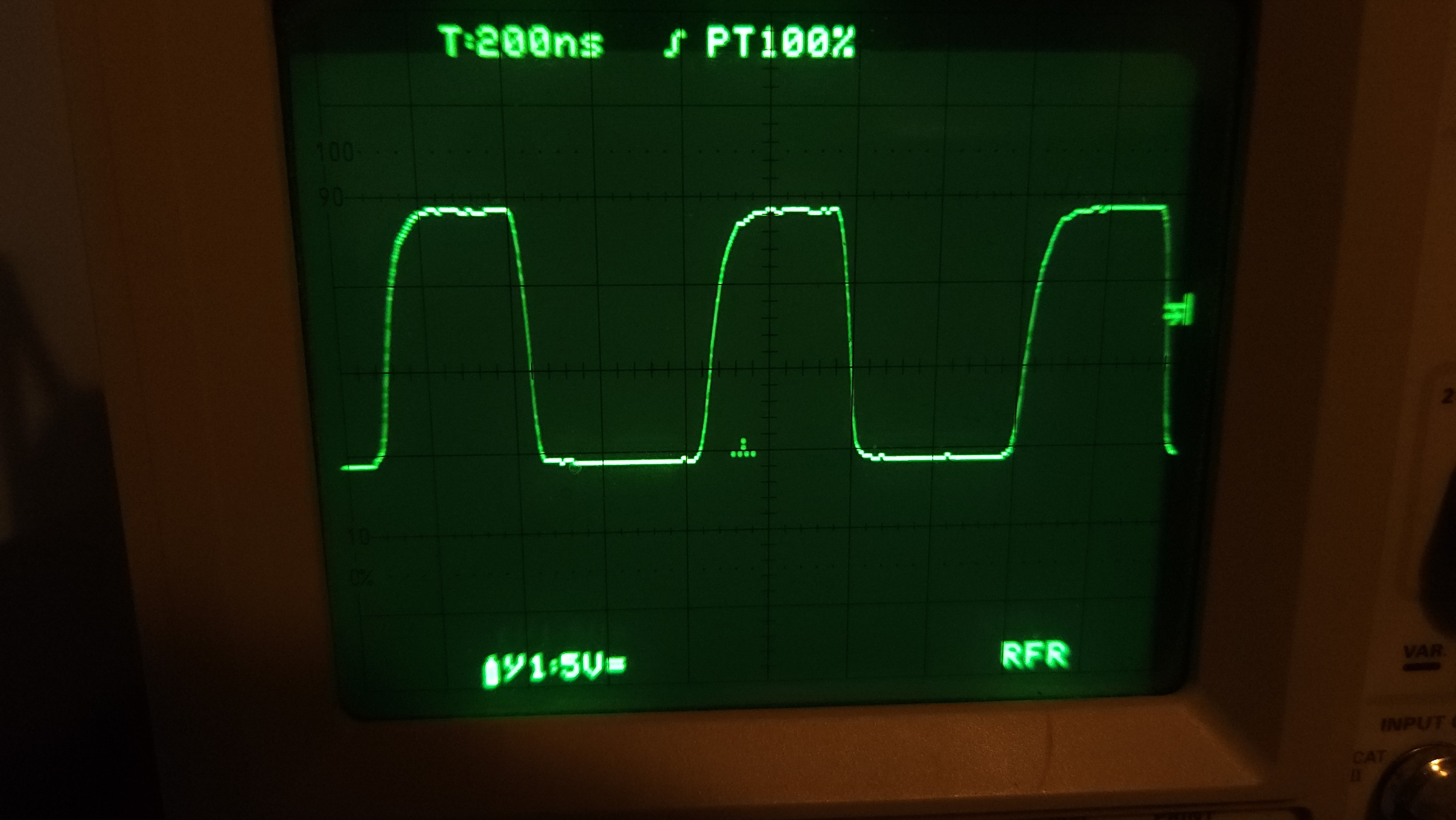
...and here is the Paraphonic's master VCO output. I've supplied it at Vcc = +15V and Vee = 0V for simplicity in this picture, different from the negative power supply rail used in the original design. Everything else is unchanged, except for the lack of a varactor diode used for precise frequency trimming which doesn't really affect the behaviour or stability.
The rise time is much less than the Lambda, at around 40ns, which makes it more attractive for feeding into the clock dividers of the top-octave generator to follow. If you look closely, the ringing caused by second-order effects is definitely there, but it's very well controlled and small compared to the oscillation amplitude. I made sure to use a film capacitor in the LC tank instead of a ceramic one to try and help with this.
The frequency stability is also equally excellent - I didn't have the opportunity to measure it directly using proper equipment in the lab at college, but it's very comparable if not slightly better than the Lambda.
The only disadvantage of this circuit is its complexity - it uses significantly more components than the Lambda's VCO, and analysis / troubleshooting is much more complicated.
In my master VCO design, I'd like to use the LC tank from the Paraphonic for its faster rise time, and the simpler negative feedback of the Lambda to reduce component count and complexity. Over the weekend I'll finalise my design and confirm it performs as expected.
How can we interface the master clock to the rest of the VCO?
As previously mentioned, the master VCO will feed into a top-octave generator, generating all 12 notes on the highest octave of the keyboard, followed by binary dividers to generate all notes in lower octaves.
Our top-octave generator, the M082B1, uses integer division of the master clock by precise factors to obtain all the notes of the highest notes on the keyboard.
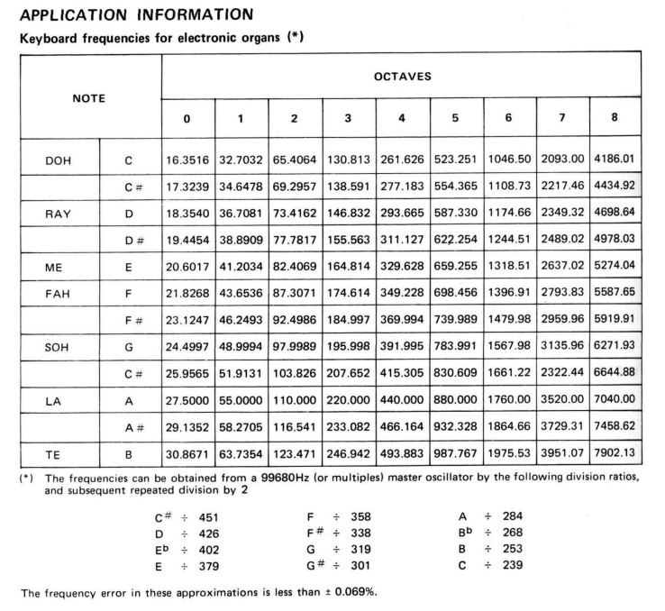
For example, to obtain a C# from our master clock generator (the lowest note in the top octave), the top octave generator divides our clock frequency by 451. In order for the sounding pitch of this note to actually be C#, we must precisely tune the frequency of our oscillator to a multiple of 99680Hz. This is a weird frequency, but I think it's specifically been chosen so that the integer division very closely approximates the true ratios between pitches.
I avoided talking about this until now, but both the Lambda and Paraphonic both have a DC voltage bias input which can be used to finely vary the frequency of our master VCO. This voltage can be set precisely to DC creating a fixed oscillation frequency, or modulated to create vibrato effects.
This is another reason why these analog clock generators were used, instead of a crystal oscillator which cannot change its oscillation frequency at all. The existence of this DC bias may also allow us to implement a phase-locked loop architecture in the future if we're feeling very fancy.
I must admit, over the past week I haven't had much opportunity to experiment with tuning or integrating with the TOGs due to time, this is definitely a task for over the weekend, and I'll report back on the success of this in next week's update, where if we're lucky we might be able to get some sound.
The VCO deadline is fast approaching
My current deadline for completing the VCO is on the 31st May, just over a week from now. I'm confident we can get a working prototype for the full VCO before this date, though I'm not sure a PCB will be ready in time.
A lot of work with the VCO will also link nicely into my next deadline (14th June), where I integrate the VCO with keyboard control through our MIDI to CV converter (currently under construction)!
Discussions
Become a Hackaday.io Member
Create an account to leave a comment. Already have an account? Log In.