 Jonathan
In my previous post, I covered the conceptual side of serial buses and networking. Having the mental model of clock lines, shared highways, and packet handshakes is nice, but theory only gets you so far. Microcontrollers are meant to touch real hardware.
For this post, I sat down with my W55MH32L-EVB board, a pack of jumper wires, a FT232RL USB to TTL board, a WIZ850io network module and the official pinout diagram to get actual signals moving across physical pins.
Step 1: Decoding the Pinout Diagram
The first hurdle when moving from software to hardware is realizing that pins wear multiple hats. Looking at the W55MH32L-EVB pinout, each physical header pin corresponds to a GPIO label (like PA2, PB10, PD14, etc.), but it also lists alternate functions in color-coded boxes (UART, SPI, I2C, ADC, timers).
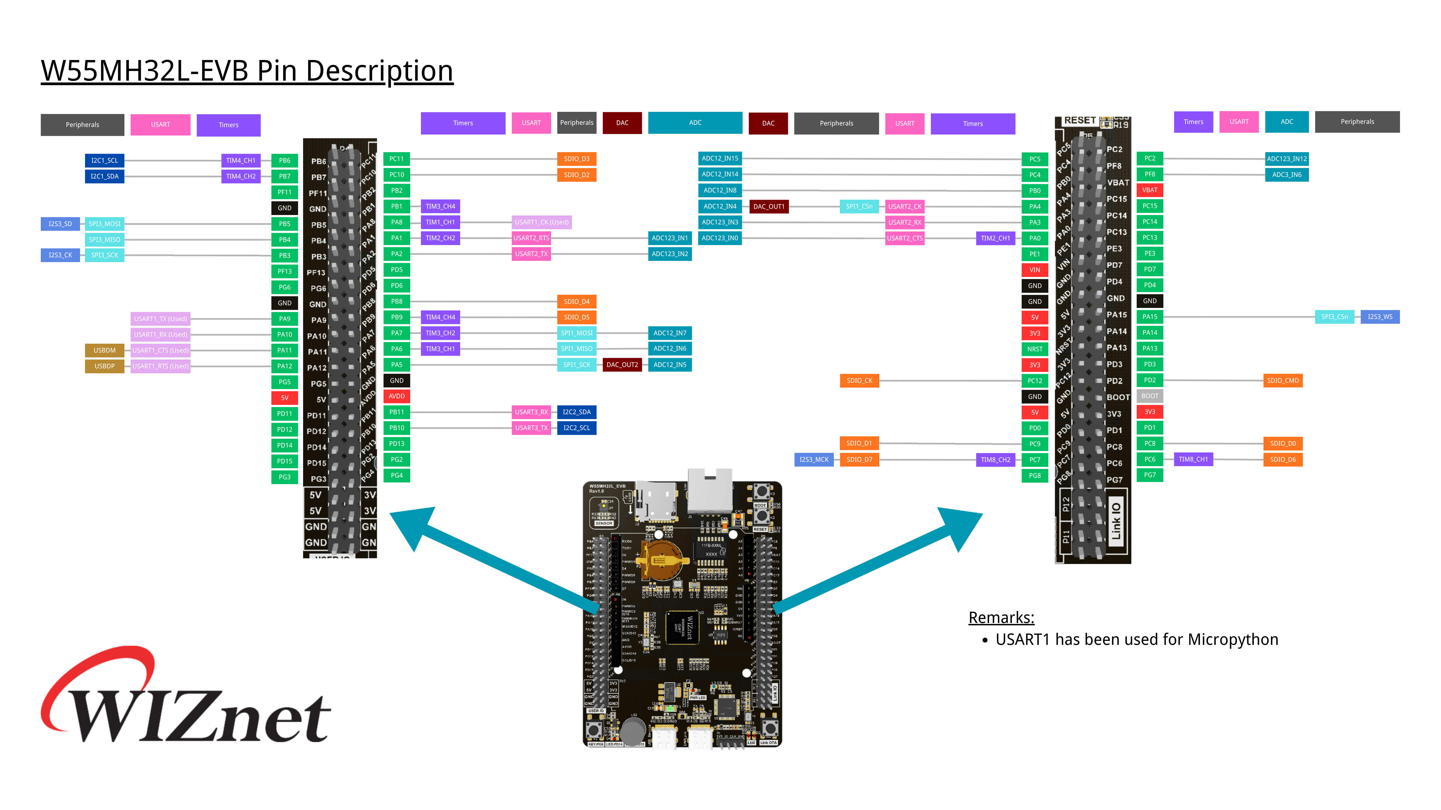
A few important observations I made early on:
- Check the reserved peripherals first: Looking closely at the pinout remarks, USART1 is already dedicated to MicroPython’s REPL / USB bridge. Trying to take over USART1 for external devices will mess with your Thonny interactive console. To talk to external hardware, choose an available spare peripheral like USART2 or USART3.
- Ground is non-negotiable: Digital signals are voltages measured relativeto ground. When connecting two separate boards together, you must connect their GND pins. Without a shared reference, 3.3V on one board might look like floating noise to the other.
- Cross your UART wires, match your SPI/I2C wires:
- UART: TX (Transmit) on the board connects to RX (Receive) on the other device, and RX connects to TX.
- I2C: SDA goes to SDA, SCL goes to SCL.
- SPI: SCK goes to SCK, MOSI goes to MOSI (or Peripheral In), MISO goes to MISO (or Peripheral Out).
The MicroPython Pattern: Classes, Objects, and Methods
Coming from standard Java and C++, MicroPython’s hardware abstraction in the machine module feels very familiar. The workflow for almost every peripheral follows the exact same object-oriented pattern:
- Import the class from the machine module (e.g., Pin, UART, I2C, SPI).
- Instantiate an object by specifying the hardware peripheral ID and configuration parameters.
- Invoke methods on that object to do real work (like.high(),.low(),.value(), or.write()).
Basic GPIO Control
Before jumping into multi-wire communication protocols, the simplest place to start is General-Purpose Input/Output (GPIO). GPIO pins let you do two fundamental things: drive a pin to a digital voltage level (Output) or read whether an external voltage is high or low (Input).
Here is the baseline pattern for controlling an output pin (like an onboard LED) and reading an input pin (like a push button):
from machine import Pin
import time

# Configure PD14 as a digital output
p_out = Pin('PD14', Pin.OUT)
# Drive the pin HIGH (3.3V) and LOW (0V)
p_out.high()
time.sleep(0.5)
p_out.low()

# Configure PG6 as a digital input
p_in = Pin('PG6', Pin.IN)
# Read the current logic state (returns 0 or 1)
button_state = p_in.value(
)print("Input pin logic state:", button_state)
Toggling a pin directly demystifies what the board is actually doing under the hood. Complex communication protocols are essentially just microcontrollers toggling pins like this at precise, blistering clock speeds.
1. UART: Talking to a PC Terminal
To test UART, I used a USB-to-TTL board connected to my computer. I wired the board’s UART TX and RX pins to the adapter (remembering to cross TX to RX and RX to TX), along with a ground wire.
On the PC, I launched a serial monitor (PuTTY) and set the baud rate to 115200.
What PuTTY does here is it it connects directly to my computer's USB ports (in this case I wanted it to monitor the port, COM4), listens for incoming raw data sent by a piece of hardware, and prints that data onto my screen
from machine import UART, Pin
import time

# Initialize UART 2 at 115200 baud
uart = UART(2, 115200)

# Transmit a greeting
uart.write("Hello from W55MH32L via UART!\r\n")

# Loopback / Echo check: listen for incoming characters
while True:
    if uart.any():
        incoming = uart.read()
        print("Received from PC:", incoming)
        # Echo it back with an acknowledgment
        uart.write(b"Echo: " + incoming)
    time.sleep(0.1)
In this piece of code, I send "Hello from W55MH32L via UART!" to the other port and the serial monitor, PuTTY picks it up. Moreover, if I send "1", "2", and "3" from the serial monitor on my computer (by typing it on my keyboard):
- The microcontroller console prints:
Received from PC: b'1',b'2',b'3' - The PC serial monitor receives:
Echo: 1
2. I2C: Scanning the Bus for Devices
If we try running the following script on the board I am using without anything plugged into the board:
from machine import I2C, Pin

i2c = I2C(1)
print(i2c.scan())
we get the following in our microcontroller console:
The way I2C can identify the different devices connected to its two lines are through addresses but here we see that there are 9 even though I have nothing connected to the board... What's going on?!
What is happening here is that address 56 is just a normal sensor on the board. I was confused at first but after more research I realized the board itself has a sensor on it, an AHT20 temperature and humidity sensor.
However, the block of 80 to 87 comes from a single EEPROM memory chip pretending to be eight separate devices. Smaller memory chips split their storage into eight sections and use those extra addresses (80 through 87) like room numbers to pick which section you want to read from. Alternatively, if it's a larger chip, its address-setting pins might just be ungrounded and "floating, " making the chip mistakenly answer to all eight numbers during the scan.
3. SPI: High-Speed Synchronous Transfers
SPI is considerably faster than UART and I2C, and it requires explicit Chip Select (CS) pin handling. Notice how our earlier GPIO knowledge ties right back into this: while the SPI class handles the clock and data lines, you control the CS line using a standard digital output Pin.
Because SPI devices are active-low, you drive CS LOW to select the device, perform your transfer, and pull CS back HIGH to deselect it.
For this SPI experiment I used a WIZ850io network module with the following pinout.
Then I looked at the board pinout and connected the appropriate pins.
from machine import Pin, SPI
import time

spi = SPI(1, baudrate=5_000_000, polarity=0, phase=0)
cs  = Pin("PA4", Pin.OUT)
rst = Pin("PA3", Pin.OUT)

# Optional hardware reset
rst.value(0)
time.sleep_ms(10)
rst.value(1)
time.sleep_ms(200)
cs.value(1)

# deselect
cs.value(0)

spi.write(bytearray([0x00, 0x39, 0x00]))
print(spi.read(1))cs.value(1)
This script sets up a microcontroller to talk to an external device (like a sensor or display) using high-speed SPI communication: it first configures the data line speed and pins, taps the reset pin (rst) to wake the chip up cleanly, and then uses the chip-select pin (cs) like picking up and hanging up a phone, pulling it LOW to say "listen to me, " sending 3 bytes of command data with spi.write(), reading back 1 byte of response data with spi.read(), and pulling it back HIGH to end the conversation.
The result we should get is an answer from the microcontroller console that says "b'0x04'"
Key Takeaways So Far
- GPIO is the foundation: Whether toggling an LED on PD14 or toggling a Chip Select line on PA4, basic digital I/O is the building block for larger peripheral control.
- Always consult the pinout legend: Spare peripherals are easy to work with; overlapping a pin with an internal trace or the REPL bridge will leave you wondering why nothing prints.
- Strings vs. Bytes: When calling.write(), MicroPython expects bytes-like objects (e.g., b"text" or bytearray([...])), not standard Python Unicode strings. Forgetting the b prefix is easily the most common syntax error beginners hit.
- The hardware loop: The sequence of Import,Instantiate,andMethod Calls remains consistent whether you are driving a simple pin or running a full bus protocol.
Now that the basic serial pipes and GPIOs are verified and working, the next logical step is moving into network communication using the board's onboard Ethernet controller and socket libraries.
Discussions
Become a Hackaday.io Member
Create an account to leave a comment. Already have an account? Log In.