
 Jonathan
-
Bring the W55MH32L Online: Ethernet + Network Applications
an hour ago • 0 commentsWhile typical beginner microcontrollers rely on external Wi-Fi shields or USB dongles, having a hardwired RJ45 Ethernet jack directly on the board changes the game for stability, deterministic latency, and reliability. In this post, I will walk through how the microcontroller interfaces with its internal Ethernet controller in MicroPython, how to bring up the network interface using both static addressing and DHCP, and the core application-layer protocols that make connected hardware tick.
Connecting the Dots: SPI Meets Ethernet
Before looking at the code, it is worth understanding the internal architecture. The onboard Ethernet controller operates as an SPI peripheral. Even though it resides on the same PCB, the main MCU communicates with it just like any external SPI chip: using a clock line, data lines, and dedicated control pins for Chip Select (CS), Reset (RST), and Power Down (PWN).
A common trap when configuring this board is peripheral selection. The board exposes multiple SPI buses, but internally, the WIZnet Ethernet hardware is wired to SPI 2, not SPI 1. Pinning it correctly makes the difference between a live link and a silent board.
Bringing Up the Interface: Code & Configuration
MicroPython provides the
networkmodule, which contains pre-built drivers for the WIZnet chip family (network.WIZNET5K). Connecting to the network follows a clean, sequential flow: configure the SPI bus and control pins, instantiate the Network Interface Controller (NIC), activate it, and assign IP configuration parameters.Depending on your deployment model, you will configure the interface using either a Static IP or dynamic addressing via DHCP.
Approach 1: Static IP Configuration
A static IP is the standard approach for embedded servers, internal dashboards, or industrial field nodes where other systems need an unchanging, predictable address to reach the board.
import network
import time
from machine import Pin, SPI

# 1. Network static configuration parameters
NET_IP = "192.168.1.20"
NET_SN = "255.255.255.0"
NET_GW = "192.168.1.1"
NET_DNS = "8.8.8.8"

# 2. Initialize the internal SPI 2 bus at 8 MHz
spi = SPI(2, baudrate=8_000_000, polarity=0, phase=0)

# 3. Configure dedicated hardware control pins
cs = Pin("PB12", Pin.OUT)
rst = Pin("PD9", Pin.OUT)
pwn = Pin("PE15", Pin.OUT, value=0)

# 4. Instantiate the WIZnet controller object and activate
nic = network.WIZNET5K(spi, cs, rst)
nic.active(True)

# 5. Apply the static network configuration (IP, Subnet, Gateway, DNS)
nic.ifconfig((NET_IP, NET_SN, NET_GW, NET_DNS))

print("Ethernet initialized with Static IP!")
print("Board IP configuration:", nic.ifconfig())
Once the script runs, verify the link by opening a terminal on any computer connected to the same subnet:
Bash
ping 192.168.1.20
Seeing zero packet loss and instant ping responses confirms that the board is officially a reachable node on the local network.
Approach 2: Dynamic IP via DHCP
If you are deploying devices across unknown client networks or home routers where you don't control the subnet range, hardcoding IPs creates conflicts. DHCP allows the board to request an IP address, gateway, and DNS configuration automatically from the local router.
Because DHCP negotiation requires a multi-step handshake across the wire (DORA: Discover, Offer, Request, Acknowledge), we instruct the driver to use "dhcp" and poll until the router completes the assignment:
import time
import network
from machine import Pin, SPI

# 1. Initialize the internal SPI 2 bus at 8 MHz
spi = SPI(2, baudrate=8_000_000, polarity=0, phase=0)

# 2. Configure dedicated hardware control pins
cs = Pin("PB12", Pin.OUT)
rst = Pin("PD9", Pin.OUT)
pwn = Pin("PE15", Pin.OUT, value=0)

# 3. Instantiate the WIZnet controller object and activate
nic = network.WIZNET5K(spi, cs, rst)
nic.active(True)

# 4. Request network configuration dynamically via DHCP
print("Requesting IP address via DHCP...")
nic.ifconfig("dhcp")

# 5. Wait for the DHCP...
Read more » -
Reading Pinouts, Toggling GPIOs, and Talking Serial in Mic
2 hours ago • 0 commentsIn my previous post, I covered the conceptual side of serial buses and networking. Having the mental model of clock lines, shared highways, and packet handshakes is nice, but theory only gets you so far. Microcontrollers are meant to touch real hardware.
For this post, I sat down with my W55MH32L-EVB board, a pack of jumper wires, a FT232RL USB to TTL board, a WIZ850io network module and the official pinout diagram to get actual signals moving across physical pins.
Step 1: Decoding the Pinout Diagram
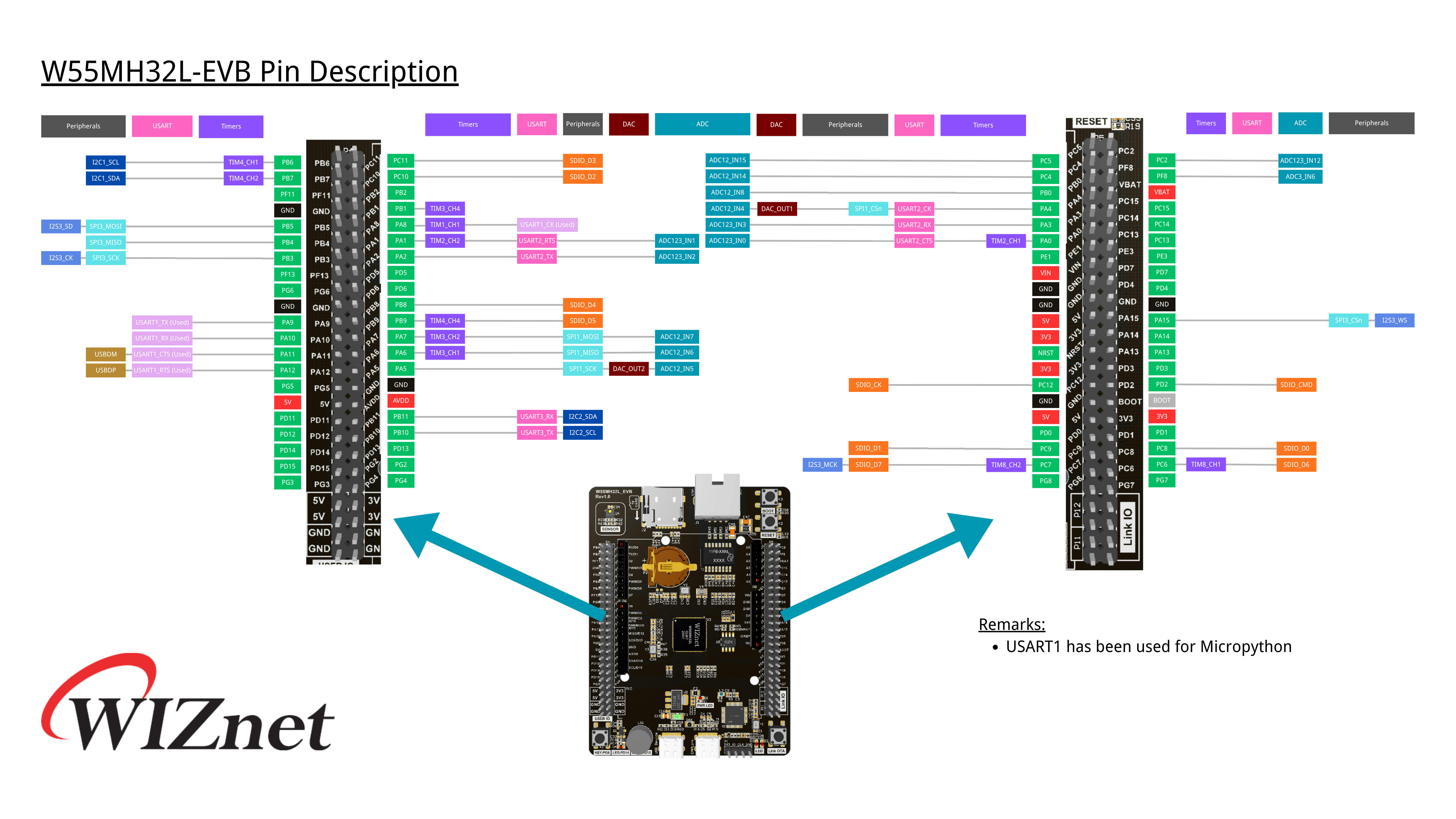
The first hurdle when moving from software to hardware is realizing that pins wear multiple hats. Looking at the W55MH32L-EVB pinout, each physical header pin corresponds to a GPIO label (like PA2, PB10, PD14, etc.), but it also lists alternate functions in color-coded boxes (UART, SPI, I2C, ADC, timers).
![]()
A few important observations I made early on:
- Check the reserved peripherals first: Looking closely at the pinout remarks, USART1 is already dedicated to MicroPython’s REPL / USB bridge. Trying to take over USART1 for external devices will mess with your Thonny interactive console. To talk to external hardware, choose an available spare peripheral like USART2 or USART3.
- Ground is non-negotiable: Digital signals are voltages measured relativeto ground. When connecting two separate boards together, you must connect their GND pins. Without a shared reference, 3.3V on one board might look like floating noise to the other.
- Cross your UART wires, match your SPI/I2C wires:
- UART: TX (Transmit) on the board connects to RX (Receive) on the other device, and RX connects to TX.
- I2C: SDA goes to SDA, SCL goes to SCL.
- SPI: SCK goes to SCK, MOSI goes to MOSI (or Peripheral In), MISO goes to MISO (or Peripheral Out).
The MicroPython Pattern: Classes, Objects, and Methods
Coming from standard Java and C++, MicroPython’s hardware abstraction in the machine module feels very familiar. The workflow for almost every peripheral follows the exact same object-oriented pattern:
- Import the class from the machine module (e.g., Pin, UART, I2C, SPI).
- Instantiate an object by specifying the hardware peripheral ID and configuration parameters.
- Invoke methods on that object to do real work (like.high(),.low(),.value(), or.write()).
Basic GPIO Control
Before jumping into multi-wire communication protocols, the simplest place to start is General-Purpose Input/Output (GPIO). GPIO pins let you do two fundamental things: drive a pin to a digital voltage level (Output) or read whether an external voltage is high or low (Input).
Here is the baseline pattern for controlling an output pin (like an onboard LED) and reading an input pin (like a push button):
from machine import Pin
import time

# Configure PD14 as a digital output
p_out = Pin('PD14', Pin.OUT)
# Drive the pin HIGH (3.3V) and LOW (0V)
p_out.high()
time.sleep(0.5)
p_out.low()

# Configure PG6 as a digital input
p_in = Pin('PG6', Pin.IN)
# Read the current logic state (returns 0 or 1)
button_state = p_in.value(
)print("Input pin logic state:", button_state)
Toggling a pin directly demystifies what the board is actually doing under the hood. Complex communication protocols are essentially just microcontrollers toggling pins like this at precise, blistering clock speeds.
1. UART: Talking to a PC Terminal
To test UART, I used a USB-to-TTL board connected to my computer. I wired the board’s UART TX and RX pins to the adapter (remembering to cross TX to RX and RX to TX), along with a ground wire.
On the PC, I launched a serial monitor (PuTTY) and set the baud rate to 115200.
What PuTTY does here is it it connects directly to my computer's USB ports (in this case I wanted it to monitor the port, COM4), listens for incoming raw data sent by a piece of hardware, and prints that data onto my screen
from machine import UART, Pin
import time

# Initialize UART 2 at 115200 baud
uart = UART(2, 115200)

# Transmit a greeting
uart.write("Hello from W55MH32L via UART!\r\n")

# Loopback / Echo check:...
Read more » -
First Post!
5 days ago • 0 commentsHi all, I decided to start this hackaday account to document my journey of learning electronics.
While I have some programming background in Java and C++ from high school courses and built Lego robotics in elementary school, I felt a bit self-conscious saying I wanted to pursue electrical engineering without hands-on microcontroller experience.
On social media, I see people creating cool but simple projects using materials such as a microcontroller, a few wires, motors, sensors, and some code. While that definitely glosses over the circuit design, debugging, and hardware constraints, it made me eager to explore.
Accompanying me on this journey is a W55MH32L_EVB board. Browsing the quick reference guide, the first thing that caught my eye was its support for MicroPython. Having standard Python syntax available on bare metal makes the learning curve much friendlier. The board also features an integrated Ethernet port, allowing it to interface directly with local networks or the internet.
![Picture of W55MH32L_EVB Board Connected to Laptop]()
Getting started physically was pretty straightforward: I plugged a USB-C cable into the DAP-LINK port to handle power and programming, opened Thonny IDE, pointed the interpreter to generic MicroPython, and had a working session right away. Something interesting I discovered was that MicroPython uses Read-Eval-Print Loop or REPL. It is an interactive programming environment that takes user inputs, executes them, and returns the result immediately.
Instead of writing a full program, saving it, compiling/running it, and checking the output, a REPL lets you run code one line or expression at a time.
Something cool I discovered is that I can write algebraic expressions in the shell and it will be evaluated.
Before diving into complex projects, I spent the past few days wrapping my head around the basic communication protocols and networking features exposed on the board’s pinout.
Hardware Communication Protocols
I spent some time looking at how microcontrollers actually talk to outside components. Technically, they are called Serial Communication Protocols. However we need to first, we need to start with learning about buses and clocks:
- A bus is a shared communication highway (traces or wires) that lets multiple devices exchange data without dedicated point-to-point connections turning the board into unmanageable copper spaghetti.
- A clock (SCLK) provides the electrical heartbeat, a square wave toggling between logic HIGH (3.3V) and LOW (0V), giving digital logic distinct, synchronized sampling points.
Now we can start looking at the some of those different communication protocols
- UART (Universal Asynchronous Receiver-Transmitter): UART only needs two data lines: a transmit line (TX) and a receive line (RX). You simply cross them over; TX on one side goes to RX on the other, and vice versa. Basically, one device can send its information to the second device whenever it wants, and the second device does the same. This is what makes it asynchronous. However both devices agree on something called a baud rate, which can be analogous to two people agreeing on a talking pace before the conversation starts.
- SPI: A faster, synchronous protocol that uses separate lines for sending data (MOSI), receiving data (MISO), and clocking, plus a chip-select pin for each connected device. One device is always the master and controls the clock, while the other devices are slaves/peripherals that respond to it. The chip-select lets the master tell any of the peripherals to “wake up” and receive/send data.
- I2C (Inter-Integrated Circuit): I2C is a two-wire bus (one wire, SDA, for data and another wire, SCL, for the clock) designed to connect multiple sensors or chips along the same two shared lines using individual device addresses. Again, one device is always the master; however, to talk to the other devices, each of the other connected devices have unique addresses that the master can use to identify each of them. ...


 Lutetium