 Ken Yap
So you have an old microcomputer board that has a UART but no PIO. Maybe one like mine. No chance then of driving a couple of digital I/O lines unless you add a PIO chip?
Hmm, let's look at the data sheet for the Intel 8251, a typical UART of a bygone era. Here's part of the page describing the modem lines.
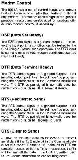
These lines were intended to for handshaking between the UART and the data set. In the past this meant the modem, but these days it could be a PC talking to the microcomputer through a serial interface.
If you are don't require handshake, then DTR and RTS can be used as output lines, and DSR can be used as an input line. CTS is an input line, but is not directly readable by the CPU, it only has an effect on the transmit buffer.
Let me cut to the chase. It works.
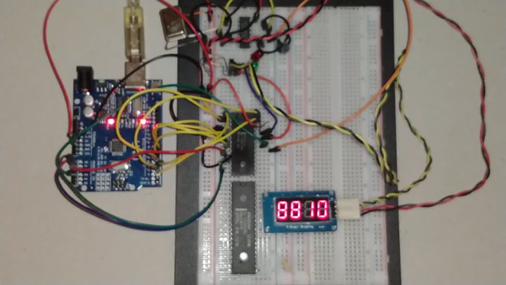
And here's a short video of it in action. The test setup on the Arduino Uno uses pins 2-9 to drive the data pins of the UART, A0 to drive the Control/~Data line, A1 to drive the ~Read line, A2 to drive the ~Write line and A3 to drive the Reset line. On a MCU board these would already be part of the circuit and you just have to program the UART appropriately.
Here is the program:
//
// Drive 8251 UART with Arduino
// Pins 2-9 are connected to D0-D7
// Pins A0-A3 are connected as #define below
//

#define CNOTD A0
#define READ  A1
#define WRITE A2
#define RESET A3
#define DTRBIT 0x02
#define RTSBIT 0x20

byte cmdinst = 0;

void init8251()
{
  pinMode(CNOTD, OUTPUT);
  pinMode(READ, OUTPUT);
  pinMode(WRITE, OUTPUT);
  pinMode(RESET, OUTPUT);
  digitalWrite(CNOTD, HIGH);
  digitalWrite(READ, HIGH);
  digitalWrite(WRITE, HIGH);
  digitalWrite(RESET, HIGH);  // RESET
  delay(1);
  digitalWrite(RESET, LOW);  // release
  delay(1);
  writecmd(0x4e); // mode: x16, 8 bit, 1 stop bit
  writecmd(0x10); // command: error reset
}

void writecmd(byte b)
{
  for (byte i = 2; i < 10; i++) {
    pinMode(i, OUTPUT);
  }
  for (byte i = 2; i < 10; i++) {
    digitalWrite(i, b & 0x1 ? HIGH : LOW);
    b >>= 1;
  }
  digitalWrite(WRITE, LOW); // pulse /W
  delayMicroseconds(1);
  digitalWrite(WRITE, HIGH);
}

byte readstatus()
{
  byte b = 0;
  for (byte i = 2; i < 10; i++) {
    pinMode(i, INPUT_PULLUP);
  }
  digitalWrite(READ, LOW); // lower /R
  delayMicroseconds(1);
  for (byte i = 2; i < 10; i++) {
    b >>= 1;
    if (digitalRead(i) == HIGH)
      b |= 0x80;
  }
  digitalWrite(READ, HIGH); // raise /R
  return (b);
}

inline void dtr0()
{
  writecmd(cmdinst |= DTRBIT);  // /DTR = 0
}

inline void dtr1()
{
  writecmd(cmdinst &= ~DTRBIT); // /DTR = 1
}

inline void rts0()
{
  writecmd(cmdinst |= RTSBIT);  // /RTS = 0
}

inline void rts1()
{
  writecmd(cmdinst &= ~RTSBIT); // /RTS = 1
}

// First test program
//
void blink()
{
  dtr0();      // /DTR antiphase to /RTS
  delay(500);
  for (;;) {
    dtr1();
    rts0();
    delay(500);
    rts1();
    dtr0();
    delay(500);
  }
}

/*
  Second test program

  Program for displaying counting from 0 - 9999 modified from
  www.funwidelectronics.blogspot.in

  This source code is modified from :
  https://blog.3d-logic.com/2015/01/21/arduino-and-the-tm1637-4-digit-seven-segment-display/

  Thanks for the code
*/

#define clk0 rts0
#define clk1 rts1
#define data0 dtr0
#define data1 dtr1

byte digits[] = { 0x3f, 0x06, 0x5b, 0x4f, 0x66, 0x6d, 0x7d, 0x07, 0x7f, 0x6f };

void start(void)
{
  clk1();
  data1();
  delayMicroseconds(5);
  data0();
  clk0();
  delayMicroseconds(5);
}

void stop(void)
{
  clk0();
  data0();
  delayMicroseconds(5);
  clk1();
  data1();
  delayMicroseconds(5);
}

bool writebyte(byte value)
{
  for (byte i = 0; i < 8; value >>= 1, i++) {
    clk0();
    delayMicroseconds(5);
    if (value & 0x1)
      data1();
    else
      data0();
    delayMicroseconds(5);
    clk1();
    delayMicroseconds(5);
  }
  // wait for ACK (not available in this implementation)
  clk0();
  delayMicroseconds(5);
  //pinMode(data, INPUT);
  clk1();
  delayMicroseconds(5);
  //bool ack = digitalRead(data) == 0;
  //pinMode(data, OUTPUT);
  return true;
}

void writenumber(byte first, byte second, byte third, byte fourth)
{
  start();
  writebyte(0x40);
  stop();
  start();
  writebyte(0xc0);
  writebyte(first);
  writebyte(second);
  writebyte(third);
  writebyte(fourth);
  stop();
}

void inittm1637()
{
  start();
  writebyte(0x89); // for changing the brightness (0x88-dim 0x8f-bright)
  stop();
}

void tm1637()
{
  for (;;) {
    for (int j = 0; j < 10000; j++) {
      writenumber(digits[j / 1000], digits[(j % 1000) / 100], digits[((j % 1000) % 100) / 10], digits[j % 10]);
      delayMicroseconds(50);
    }
  }
}

void setup() {
  // put your setup code here, to run once:
  // Serial.begin(9600); // in case we need serial debugging
  init8251();
  inittm1637();
}

void loop() {
  // put your main code here, to run repeatedly:
  // blink();
  tm1637();
}
A few things to note.
- There are actually 2 programs in this sketch. The first one is good old blink but alternating the LEDs, which I used to debug the basics. The second one drives the TM1637 serial display which I have used in a couple of previously published projects.
- The output pins can only be outputs so you cannot read the line. This means that any ack features of the driven peripheral can't work.
- I have not tested reading the DSR input pin, but I have confidence it will work.
- The pins are actually negated outputs so the bit manipulation is abstracted in routines. For example dtr0() actually sets the corresponding bit in the command register.
- You cannot read the state of the command register so a variable is needed to remember the current state.
- One little detail not visible: I needed pullup resistors to make the TM1637 accept the clock and data signals.
- The 8085 CPU in the corner is unused. It's for another project later.
It occurs to me that this could be a covert channel for sending data out of an MCU system. 😊
Discussions
Become a Hackaday.io Member
Create an account to leave a comment. Already have an account? Log In.
Nice idea. I'll make sure to use this technique for the #Gold186 project. Currently I've connected five '595 onto the 16 bit data & address buses plus some of the control signals so I can have an Arduino pull the CPU into reset and then "patch" in new code into the RAM. Or else I'll have to swap eproms every time I want to test during the development of the monitor/bios code.
I have a few bits free at the last '595 so I could use one of them to enable the UART as well.
Are you sure? yes | no
So you're using an Arduino board as a UART GPIO expander?
> data sheet for the Intel 8251, a typical UART of a bygone era.
The 8251 IC may be outdated, and the datasheet does a terrible job at explaining what Atmel these days calls "enhanced UART". In fact, RTS and CTS are extremely handy (hardware) flow control lines once you hook them up to, say, a bluetooth UART adapter, or when a routine happens to take longer to execute and the RX register cannot be read in time (for example you're waiting for an I2C acknowledge).
Only a select few ATmega microcontroller even have the enhanced UART feature (ATmega16U4, ATmega32U4, ..) and as RTS / CTS directly interact with the peripheral, flow control can effectively avoid data loss and corrupted transmissions without costing CPU time.
This works by disallowing the sender side to transmit more data even as the last recievable byte is still being transmitted. Devices supporting flow control usually implement transmit and receive buffers and data transfer is handled interrupt-based, using DMA or directly in hardware to achieve minimum overhead.
To name one, the popular FT232H provides 1 kB large buffers.
So in essence, flow control makes the difference between something sketchy that misses or misinterprets commands every once in a while and a solid, stable solution.
Are you sure? yes | no
No, simply using the Arduino to test the concept by simulating a microprocessor that era, e.g. Z80. In fact, the way I've wired up the testbed, it acts as a GPIO shrinker :), 12 lines used to get 3. If you had read the context I provided, the link to my project to repurpose a discarded microcontroller board, you would have understood.
Are you sure? yes | no
Yeah, sorry for the misunderstanding. The introduction still sounds like "forget about flow control, you don't need it, here's what to use the IOs for instead" though.
On the bright side, there are actually a few programmer circuits that also repurpose the handshake lines from the PC side which, if I got that now, expand the functionality of a limited pin count interface in similar manner.
like this one:
http://www.mibot.com/img/sch_orig_lrg.png
Are you sure? yes | no
I probably won't even use the serial interface on that controller board, except maybe in the experimentation stage. If I ever think of a good use for it, it will probably be as a free-standing controller and any input through transducers, as mentioned in that project's logs.
For getting a few GPIO lines from a PC, USB is the way to go, skip all that RS232 malarkey. Besides the FT232 you have mentioned, there are cheaper alternatives, like this:
https://www.ebay.com.au/itm/USB-to-UART-IIC-SPI-TTL-ISP-EPP-MEM-Converter-CH341A-Programmer-Parallel-Onboard/392186307210
or this:
https://www.electrodragon.com/product/ch341-usb-convert-flash-board-usb-ttl-iic-spi-etc/
or even this method halfway down the page if one is willing to repurpose a dongle. Turns out the CH341 has extra pins often not used when used as a converter or programmer:
http://www.zoobab.com/ch341-usb-spi-i2c-uart-isp-dongle
Chips are so cheap these days that often not all the functionality is used in typical products. The TM1637 serial to LED converter in the display module I used for testing has keypad scanning capability also.
Are you sure? yes | no