 Ken Yap
-
Cheap programmable time modules
05/04/2026 at 12:41 • 2 comments![]()
These modules can be found on AliExpress for a few cents each if you buy 5 upwards.
![]()
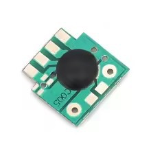
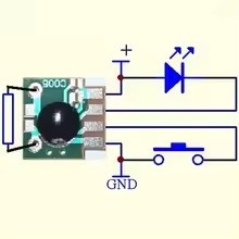
It's a 12x12 mm module with the chip under the blob, typical of other cheapies like doorbell generators. The circuit shows that a resistor "programs" the delay, between 2 seconds and 1000
secondshours. It is powered by 2V to 5V so suitable for digital logic. It's effectively a non-retriggerable monostable where a low transition on the input causes the output to go low for the programmed period. There is a reference to a selectable multiplier. I think this refers to the solder jumpers which can be used to increase the delay by 8 to the power of 0 to 3. The documentation is very scarce, there is no formula provided for calculating the resistance required. A reviewer said just as much. I'm putting a link to this on the stack in the hope that someone knows more about these.You'll need to buy $15 worth of stuff for free shipping so they could be used to top up an order to reach the threshold. I might get a few next order.
-
A gotcha with SDCC and stm8
03/28/2026 at 05:50 • 0 commentsWhen I updated my SDCC version from 4.2 to 4.5 I was vaguely aware of a change in the calling convention for STM8 MCUs, so I rebuilt the ST Standard Peripherals Library following instructions that I had developed a few years ago so that the library would have the same calling convention as my application code.
What I missed was that I had an inline assembler routine to delay a few µs. Since the calling convention had changed the first argument was passed in A, not on the stack. The effect of the error was that I was seeing occasional random glitches in the display due to the 74HC595 not getting enough time to load bits some of the time. The following one line deletion fixed that:
diff --git a/display.c b/display.c
index 34ed872..31bb77c 100644
--- a/display.c
+++ b/display.c
@@ -153,11 +153,11 @@ static void display_fill(void)
 }

 // taken from https://github.com/unfrozen/stm8_libs/blob/master/lib_delay.c
+// modified for calling convention 1
 static void delay_usecs(uint8_t usecs)
 {
        usecs;
 __asm
-       ld      a, (3, sp)
        dec     a
        clrw    x
        ld      xl,a
You can find details of the calling convention, versions 1 and 0, in the SDCC manual, part of its documentation.
-
A dumb mistake with KiCad symbols
02/01/2026 at 06:00 • 0 comments![]()
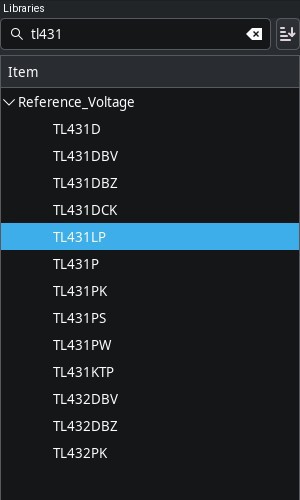
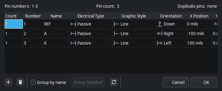
The TL431 programmable shunt regulator is a useful 3 pin chip that I use a lot. In a recent project I used it in the heart of a constant current circuit. I chose the symbol TL431DBZ which uses the SOT-23 package. Most likely I initially designed the board for PCBA and later decided to hand assemble it and use the TO-92 package. I thought it wouldn't matter since I would change the footprint to the TO-92-wide footprint. Of course I was mistaken. Here is the pin table for the TL431DBZ.
![]()
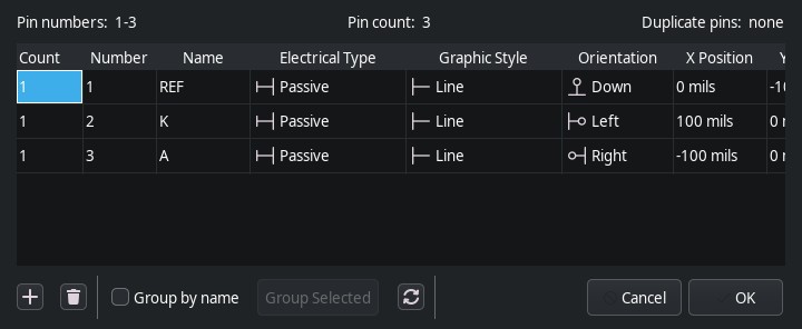
And here is the pin table for the symbol I should have chosen, the TL431LP:
![]()
Notice the pin number assignments differ. The result was that the pads in the TO-92-wide footprint weren't the electrodes I was expecting.
Fortunately 3-pin TO-92 packages can be rotated to give a different permutation of the pins and this is the hack I will use for the existing boards. The KiCad project has of course been updated.
My Pages
Projects I Like & Follow
 Ian Dunn
 Alex Xia
 CanHobby.ca
 Guy Dupont
 BlackIoT SAGL
 Joren Heit
 Michael
 Just4Fun
 Michael Wessel
 Adam Wakelin
 Alan Boris
 supermarioprof
 Markus Loeffler
 Dave
Dave twodogstar
 Wouter Minjauw
 Bohan Xu
 Silica Gel
Share this profile
ShareBits

Thank you for liking and following my #Prehistory of my homemade PERSEUS computers !

Thank you for following my Sol-20 Reproduction project Ken.

Hi Ken, thanks for the like for my TD4.
As far as a CPU it is pretty useless but it makes a great demo because of the flashing LEDs.
This seems to be a Japanese trait. When I was in Japan even the vending machines had animations. The TD4 book is half electronics and half anime imagery.
I am looking a more powerful 4 bit CPU in the same style as the TD4 (but for the prototype, using an IC PROM rather than a diode PROM). Only pencil drawings on graph paper at the moment.
Regards AlanX

A CPU with 11 TTL packages is interesting because I probably have all the parts needed but pity it doesn't do much more than flash LEDs. Looking forward to seeing your design.
Hi Ken,
I had a re-look at the TD4 and I had design a Paged version (https://cdn.hackaday.io/images/1250221502460302068.png) that increased the program space to 256x8. An ALU can be mapped in RAM space (16x4) but I did not pursue that option further (I could see better options).
Also an ALU (say an 181) could be connected to the A and B registers as inputs and the output directed to the "Zero Port". That is, replace "Move A,Z+Imm" with "Move A,ALU+Imm" etc. The Page register could be used as a function register for the ALU. The ALU would need to output Zero upon reset and to return to Zero under program control. Such is the problem with 4 bits is that you need more OpCode space.
Finally you could replace the original adder with an ALU and control the function with the Page register. You would need to be careful to be able to recover the CPU from a lock state. It was at this point I decided to build a new 4 Bit CPU from scratch.
Regards AlanX
Hi Ken,
I completely forgot, I have a redesigned TD4B version of the board (based on the one shown in my project posts: https://cdn.hackaday.io/images/5564921527557781106.png) but without the RAM and tidied up. It has not been tested (one day I will assemble it) but it should work. PM me if you want one.
AlanX
Thanks @agp.cooper
I'll think start small, with a zero bit CPU, just like I started learning juggling with zero balls. TBH I haven't progressed beyond that point. 🤣
Thank you for your comment to my #PERSEUS-8 homemade 6502 computer !
Thank you for liking my #Homemade Operational Amplifier and your comment !

Hi Ken, thanks for the like!
You've got a couple of nice projects, and I like your motto. Tinkering with electronics can be meditation.
Hello Ken, thanks for liking and following my new project, the Kobold computer, https://hackaday.io/project/164897-kobold-retro-ttl-computer !
Yes, obviously like me you appreciated the cleverness of the PDP-11 instruction set where the PC being R7, load immediate becomes load indirect R7 with autoincrement.
Hi Ken, thanks for liking my #Isetta TTL computer !