 Ken Yap
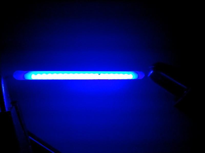
Ok, time to take a break from playing around with OOS (Old Old Stock) and explore LED filaments with the goal of making large segment displays from them.
These cost around 30¢ each from AliExpress. They come in various lengths, from 20 mm to 68 mm; in various colours; and in various voltages, starting at 3 V. They are called hard filaments as opposed to the flexible fllaments that are even more decorative. They are smaller than you might expect from the photos which are larger than life-size. They are more like toothpicks in thickness. I picked 38 mm because that size could make a digit to fit within a 100x100 mm PCB, 12 V to reduce the current requirement, and three colours: red, green and blue.
I connected it up to the power supply I described in https://hackaday.io/page/398950-assembling-a-120-w-bench-power-supply which allows me to limit the current while cranking up the voltage.
I had questions I wanted answered:
- The scanty information on the webpages don't say if there is a current limiting resistor in the filament. I doubted it.
- The nominal voltage is 12 V but what is the current curve like as you increase the voltage? I didn't want to exceed the suggested limit of 45 mA.
- How come the different colours all have nominal voltages of 12 V? Do they use different junction meterials?
Increasing the voltage until the current limit of 45 mA was reached showed a filament voltage of just over 11 V. So it was as I suspected, there there is no resistor in the filament, and there are groups of 4 blue LEDs in series then in parallel all along the length of the filament for 4 junction drops, ~ 3 V x 4. Furthermore I'm sure that other colours are produced by phosphors excited by blue LEDs rather than different junction materials, different from single LED parts. Evidence in favour is that the blue filament is neutral white colour so that's the natural emission of the LEDs. These facts would explain why somebody measured a very high current feeding them from a 12 V supply. That I wanted to avoid as it would shorten the life.
So to use them for display purposes I need to devise a constant current circuit to limit the current. They are very bright so I should apply PWM to control the brightness. The other thing I have to do is devise a way of soldering the leads to the PCB. They are quite delicate and should not be bent more times than necessary.
Discussions
Become a Hackaday.io Member
Create an account to leave a comment. Already have an account? Log In.