 Ken Yap
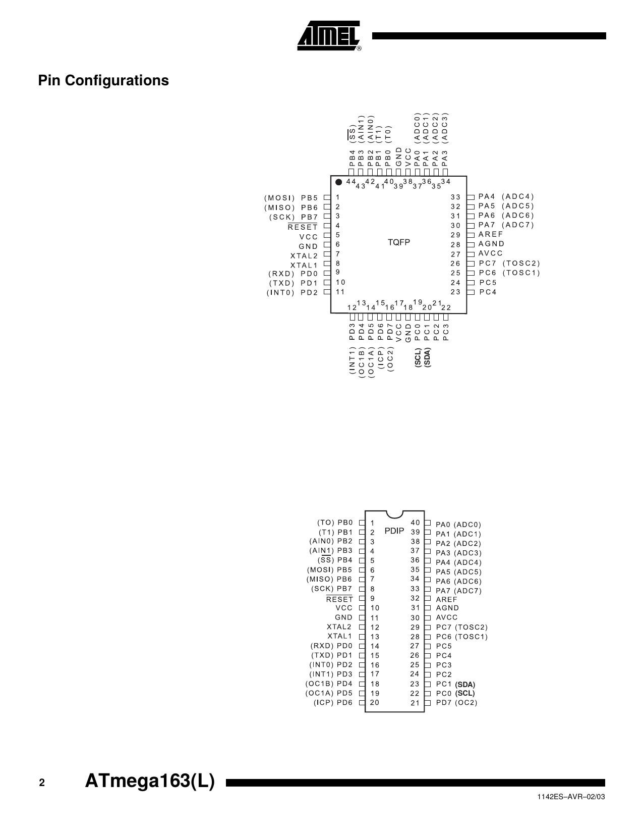
AVR at the bare silicon level using my OOS (Old Old Stock) that is, because I still have a couple of Arduinos, but programming with them will be through the Arduino HAL which hides the low-level hardware stuff.
I found another AVR MCU in my junk box, and it's an ATMEGA163L. I was curious what modifications I would have to make to my build to compile code for it. Turns out, not much. Here's the section of my Makefile which looks at the command line argument MCU=ATMEGA163 to choose different settings for the build.
MCU?=AT90S8515
CSRCS=clock.c ds3231.c i2c.c
BUILDFLAGS=-DLOWON -DRAISEDZERO # -DDS3231

ifeq "$(MCU)" "AT90S8515"
CSRCS+=at90s8515.c
BUILDFLAGS+=-DAT90S8515 -DX8_000_000 -DSIXSEGMENT
# CRTs are inside the avr-gcc distribution
CRT=crtat90s8515.o
MCUOPT=-mmcu=avr2
endif

ifeq "$(MCU)" "ATMEGA163"
CSRCS+=atmega163.c
BUILDFLAGS+=-DATMEGA163 -DX4_000_000
# CRTs are inside the avr-gcc distribution
CRT=crtatmega163.o
MCUOPT=-mmcu=avr5
endif
The MCU?=AT90S8515 establishes the default to be overriden by a command line assignment to MCU. The next two lines set the default source file list and BUILDFLAGS. As you can see the only things that change are the CRT startup file, a define that affects the source compiled, and the MCU architecture requested of the avr-gcc compiler. Fortunately the on-chip features I used are present in both MCUs. Atmel (now Microchip) did a decent job of family compatibility.
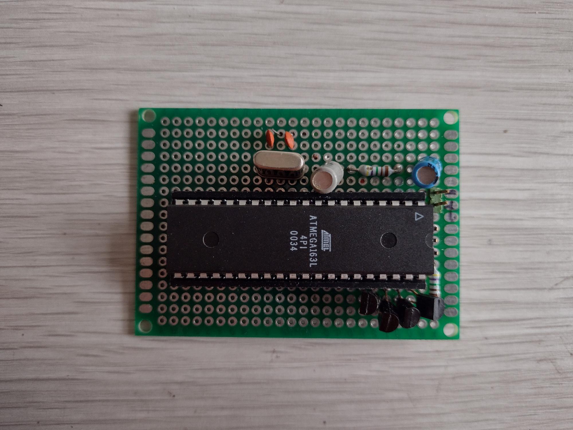
The 163 is the forerunner of the 164 which fixed some silicon bugs, hence not recommended for new designs. The L suffix means I have to change the declared crystal frequency to 4 MHz. Unfortunately the 163/164 while still available in the DIP-40 package, have a different pinout from the AT90S8515. I'm loath to have 5 boards made only to use 1, or pay money for some NOS ATMEGA164s, so I wired this up on perfboard (ugh!). I'll only need a 7805 regulator, a crystal and its load capacitors, a couple of bypass caps, and the reset RC circuit. The result is in the picture below. The regulator is underneath the board, and I have added 4 transistors as digit drivers. Preliminary testing showed the expected waveforms on the output pins so next thing to do is to connect it up to a display.
A few days later: Ok, I've cracked this one. I've connected it up to a display as shown here.

First I checked for wrong connections or bad solder joints, then I powered it up. The display was very strange, it showed the correct digits but flashed like a strobe light. Looking at the seconds colon, it was running a few times slower than designed, so the digit scan was visible. I knew it had something to do with the timer, perhaps I was scaling the clock too much. In a first round of edit, I rejigged the timers because timer 0 and 1 use the same clock source so I had to switch the 5 µs delay to use timer 2 which is independent. But the flashing persisted.
Closer reading of the datasheet showed that the MCU powers up in 1 MHz RC oscillator mode. I had to set fuse bits to use the 4 MHz crystal oscillator. A little self-education about fuse bits and how to set them using my TL866 chip programmer and I got the clock source configured to use the crystal. The slowdown factor was about 4x, hence the colon cycling at about ¼ Hz.
So I learnt something new even though it has been common knowledge for designers using the AVR for a long time. Now I can publish the sources at Github for anyone who cares and close my adventures with the AVR family at the bare silicon level.
Discussions
Become a Hackaday.io Member
Create an account to leave a comment. Already have an account? Log In.