-
Leaky transistors
4 hours ago • 0 comments
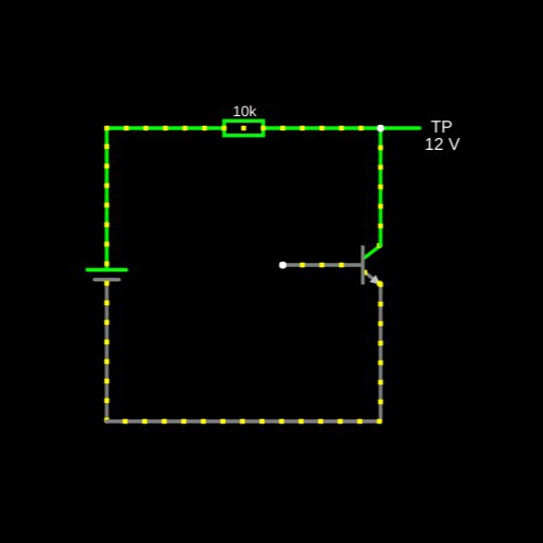
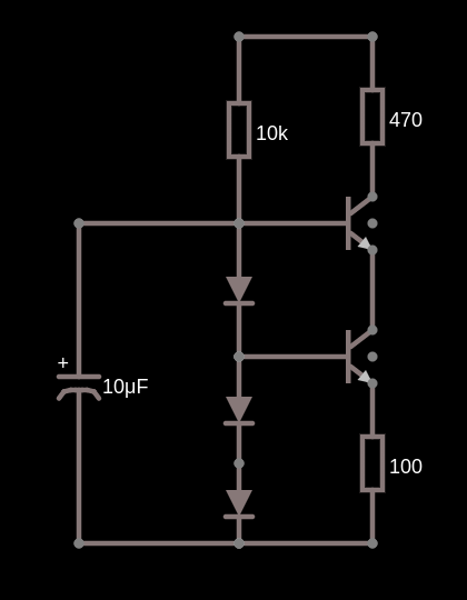
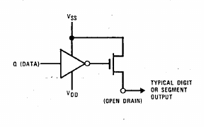
Being frustrated with encountering segments or digits that stayed partly on even when they are supposed to be off, I turned my attention to the driver transistors I was using.
I realised that these were grab bag transistors bought decades ago when I was a newbie. Being seconds (cough, rejects) they are actually poorer than pulls from circuit boards that have been verified. I had graded they by gain using a component tester. But in my newbie days I had been using them in battery driven circuits, usually not more than 6 V. Now my circuits involve higher voltages, The component tester I had used only goes up to 9 V and there is no indication of leakage or worse C-E breakdown.
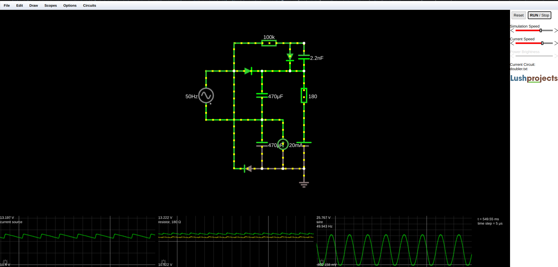
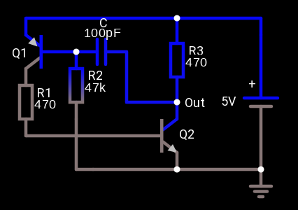
I whipped up the circuit above. I dialed up 12 V on the bench supply and connected a voltmeter across the C-E terminals. Originally I had a 100 k resistor between B and E but I decided to omit that, the better to detect leaks as any C-B leakage current would get amplified. I decided that any measurement below 12 V indicated a dodgy transistor. For example a voltage of 11.99 V corresponds to a leakage current of 1 µA.
For PNP transistors, I just reversed the power supply. Result is I culled about 15 - 20 % of the grab bag stock. Now I can use the OOS (Old Old Stock) with greater confidence.
-
Delving into Picolibc
04/05/2025 at 10:48 • 0 comments
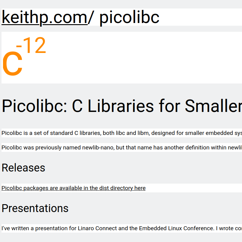
Picolibc is a set of standard C libraries, libc and libm, for smaller embedded systems with limited ROM and RAM. It's derived from newlib and AVR libc. It is actively developed and can be cloned from Github. ARM and RISC-V are the main testing targets.
As you can see from the screenshot, there is a link to a very informative presentation about the history of Picolibc. Keith Packard is familiar to me from his previous work with Freededsktop and the X desktop server. I must look into the other interesting projects in Keith's rabbit hole.
The reason I started looking into picolibc was the need to have a crt0.o for an upcoming bare metal MCU project. The libc and libm might be used later. Surprisingly there were few source candidates on the Internet for the MCU architecture I had in mind, but I found one under the picocrt subdirectory of picolibc.
A look in the newlib-cygwin source shows the difference in the size of the targets.
$ ls newlib-cygwin/newlib/libc/sys
a29khif  d10v      h8300hms  Makefile.inc  or1k   sh         sysnecv850  tic80   z8ksim
amdgcn   epiphany  h8500hms  mmixware      rdos   sysmec     sysvi386    tirtos
arm      esp       m88kbug   netware       rtems  sysnec810  sysvnecv70  w65
Compare this to the list of picolib targets for crt0.o:
$ ls picolibc/picocrt/machine
aarch64  arc  arc64  arm  m68k  mips  msp430  nios2  powerpc  riscv  sh  sparc  x86  xtensa
Many of the modern 32 and 64 bit MCUs are covered. ARM gets you the RPi, STM32, and so forth. Xtensa gets you the ESP32 family. RISC-V gets you the rising MCUs, including the newer ESP32s.
The build system is modern, it uses meson and ninja. Once configured, compiling was super-fast.
The task that took most time for me was finding and installing an appropriate cross toolchain for the MCU. When that is done, you have to write a meson configuration file to generate the MCU configuration, or use one of the existing ones. It's possible that the tool prefix won't be what the configuration expects. You can either customise the config file, or make symlinks to the tool names expected. For example I have this link in /usr/local/bin:
/usr/local/bin/arm-none-eabi-gcc -> ~/.arduino15/packages/STMicroelectronics/tools/xpack-arm-none-eabi-gcc/14.2.1-1.1/bin/arm-none-eabi-gccAfter building, several versions of crt0.o were created, for none, normal, minimal, semihosted, and hosted. I'll probably be using the normal one which sets up the MCU for a C program and then calls main().
More later when I start on the MCU project in question.
-
Cheap touch switches
04/03/2025 at 12:22 • 0 comments
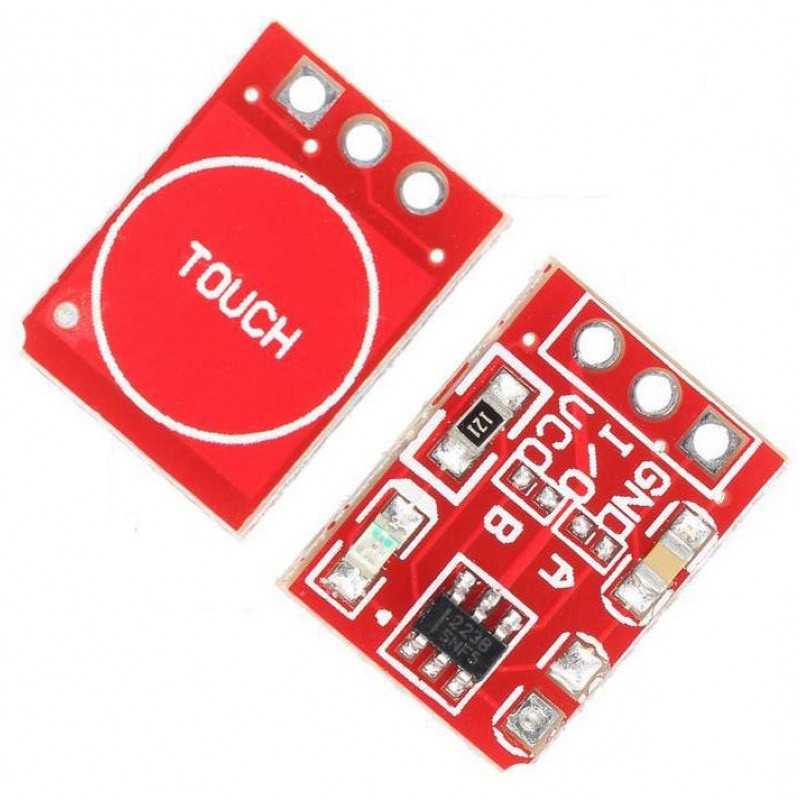
While prowling AliExpress in search of novel stuff, I came across touch sensor switches for about 10¢ each quantity 50.
They are not new. The datasheet for the TTP223 chip at the heart of this module dates from August 2009. The attraction of this combo is that it is more than just a NO SPST switch. It can output either high or low level by selecting a solder jumper. Another solder jumper changes between momentary and toggle modes. The module also does switch debouncing, so you can skip doing that in the MCU firmware. It works with both 5 V and 3.3 V logic.
I connected one up to an Arduino (actually the ESP8266 Uno form factor equivalent) and verified that it works as advertised. I was at first disappointed because I had connected the module with jumper wires on a breadboard. But the proximity of the metal in the breadboard pin sockets disrupted the operation. Only when I moved it above the breadboard did it work. There is also a status LED on the back of the module which shines through the PCB a little. Depending on your application, this might or might not be annoying. You could always desolder the LED.
There is little point in describing setup and operation when there is a good resource from Instructables.
So, an alternative to the tactile switches I have been using, for a little more cost and surface area.
-
Experiments with LED filaments
03/25/2025 at 10:17 • 0 comments
Ok, time to take a break from playing around with OOS (Old Old Stock) and explore LED filaments with the goal of making large segment displays from them.
These cost around 30¢ each from AliExpress. They come in various lengths, from 20 mm to 68 mm; in various colours; and in various voltages, starting at 3 V. They are called hard filaments as opposed to the flexible fllaments that are even more decorative. They are smaller than you might expect from the photos which are larger than life-size. They are more like toothpicks in thickness. I picked 38 mm because that size could make a digit to fit within a 100x100 mm PCB, 12 V to reduce the current requirement, and three colours: red, green and blue.
I connected it up to the power supply I described in https://hackaday.io/page/398950-assembling-a-120-w-bench-power-supply which allows me to limit the current while cranking up the voltage.
I had questions I wanted answered:
- The scanty information on the webpages don't say if there is a current limiting resistor in the filament. I doubted it.
- The nominal voltage is 12 V but what is the current curve like as you increase the voltage? I didn't want to exceed the suggested limit of 45 mA.
- How come the different colours all have nominal voltages of 12 V? Do they use different junction meterials?
Increasing the voltage until the current limit of 45 mA was reached showed a filament voltage of just over 11 V. So it was as I suspected, there there is no resistor in the filament, and there are groups of 4 blue LEDs in series then in parallel all along the length of the filament for 4 junction drops, ~ 3 V x 4. Furthermore I'm sure that other colours are produced by phosphors excited by blue LEDs rather than different junction materials, different from single LED parts. Evidence in favour is that the blue filament is neutral white colour so that's the natural emission of the LEDs. These facts would explain why somebody measured a very high current feeding them from a 12 V supply. That I wanted to avoid as it would shorten the life.
So to use them for display purposes I need to devise a constant current circuit to limit the current. They are very bright so I should apply PWM to control the brightness. The other thing I have to do is devise a way of soldering the leads to the PCB. They are quite delicate and should not be bent more times than necessary.
-
Nearing the end of my AVR adventures
03/23/2025 at 08:34 • 0 comments
AVR at the bare silicon level using my OOS (Old Old Stock) that is, because I still have a couple of Arduinos, but programming with them will be through the Arduino HAL which hides the low-level hardware stuff.
I found another AVR MCU in my junk box, and it's an ATMEGA163L. I was curious what modifications I would have to make to my build to compile code for it. Turns out, not much. Here's the section of my Makefile which looks at the command line argument MCU=ATMEGA163 to choose different settings for the build.
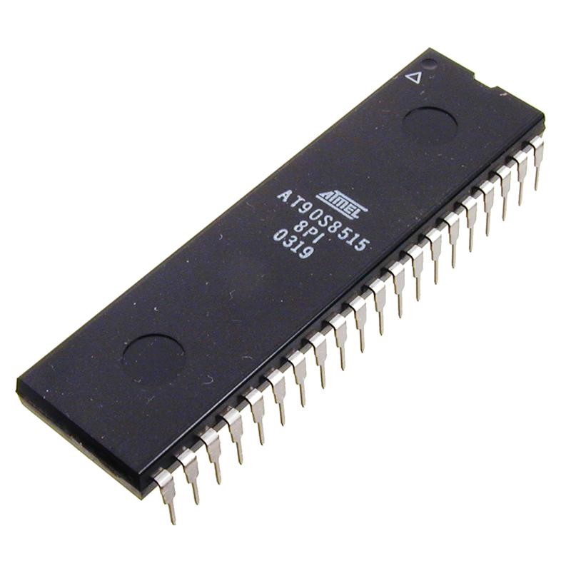
MCU?=AT90S8515
CSRCS=clock.c ds3231.c i2c.c
BUILDFLAGS=-DLOWON -DSIXSEGMENT -DRAISEDZERO # -DDS3231

ifeq "$(MCU)" "AT90S8515"
CSRCS+=at90s8515.c
BUILDFLAGS+=-DAT90S8515 -DX8_000_000
# CRTs are inside the avr-gcc distribution
CRT=crtat90s8515.o
MCUOPT=-mmcu=avr2
endif

ifeq "$(MCU)" "ATMEGA163"
CSRCS+=atmega163.c
BUILDFLAGS+=-DATMEGA163 -DX4_000_000
# CRTs are inside the avr-gcc distribution
CRT=crtatmega163.o
MCUOPT=-mmcu=avr5
endif
The MCU?=AT90S8515 establishes the default to be overriden by a command line assignment to MCU. The next two lines set the default source file list and BUILDFLAGS. As you can see the only things that change are the CRT startup file, a define that affects the source compiled, and the MCU architecture requested of the avr-gcc compiler. Fortunately the on-chip features I used are present in both MCUs. Atmel (now Microchip) did a decent job of family compatibility.
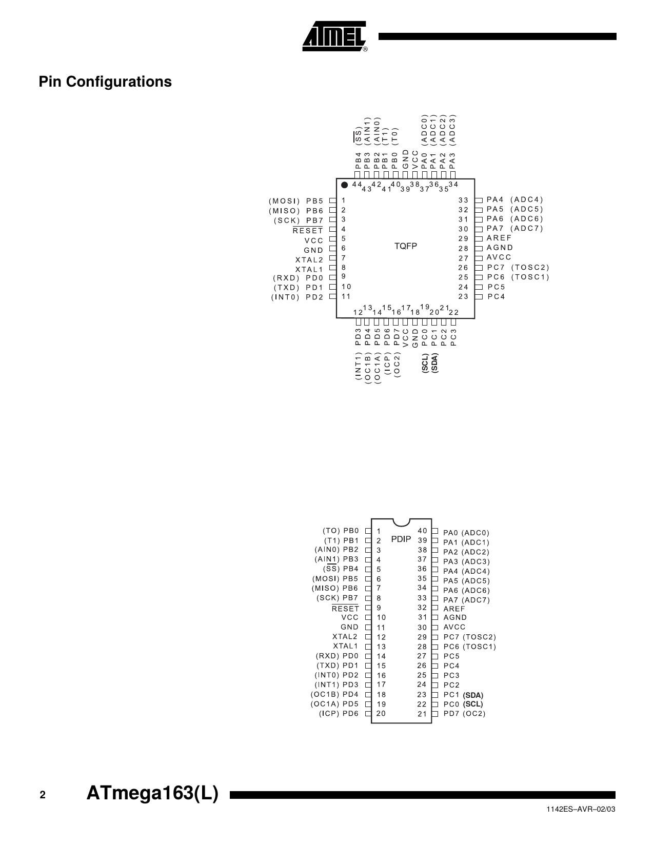
The 163 is the forerunner of the 164 which fixed some silicon bugs, hence not recommended for new designs. The L suffix means I have to change the declared crystal frequency to 4 MHz later. Unfortunately the 163/164 while still available in the DIP-40 package, have a different pinout from the AT90S8515. I'm loath to have 5 boards made only to use 1, or pay money for some NOS ATMEGA164s, so I might wire this up on perfboard (ugh!). I'll only need a 7805 regulator, a crystal and its load capacitors, a couple of bypass caps, and the reset RC circuit. I may live to regret using perfboard ☹️. We shall see.
-
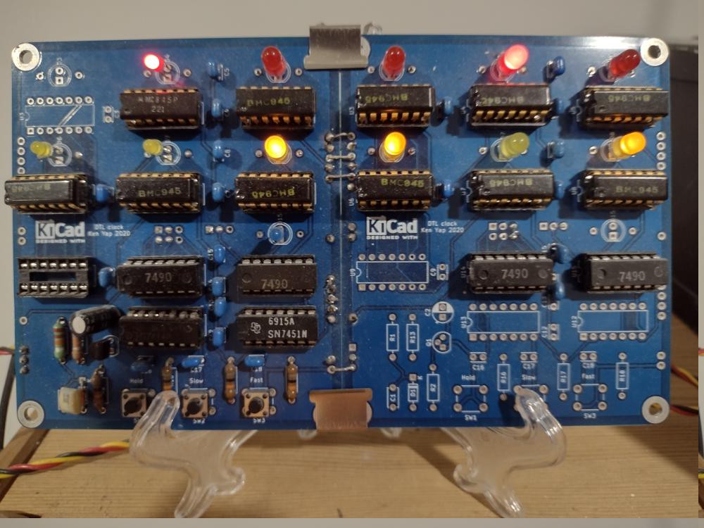
A use for JLCPCB cardboard boxes
03/19/2025 at 07:08 • 0 comments
Every 5 or 10 PCBs I order from JLCPCB I get a 15 x 15 cm cardboard box. I have accumulated many now. They are quite sturdy and a shame to put into paper recycling after one use.
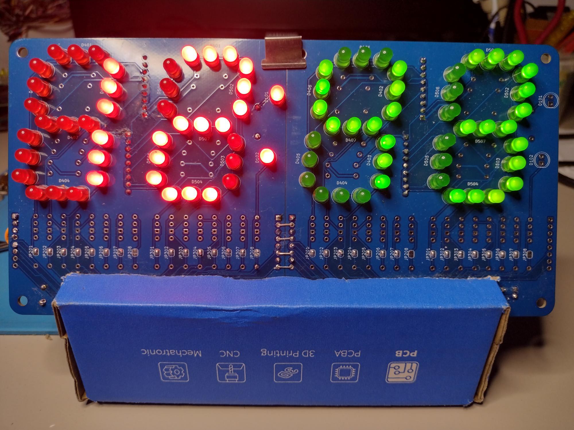
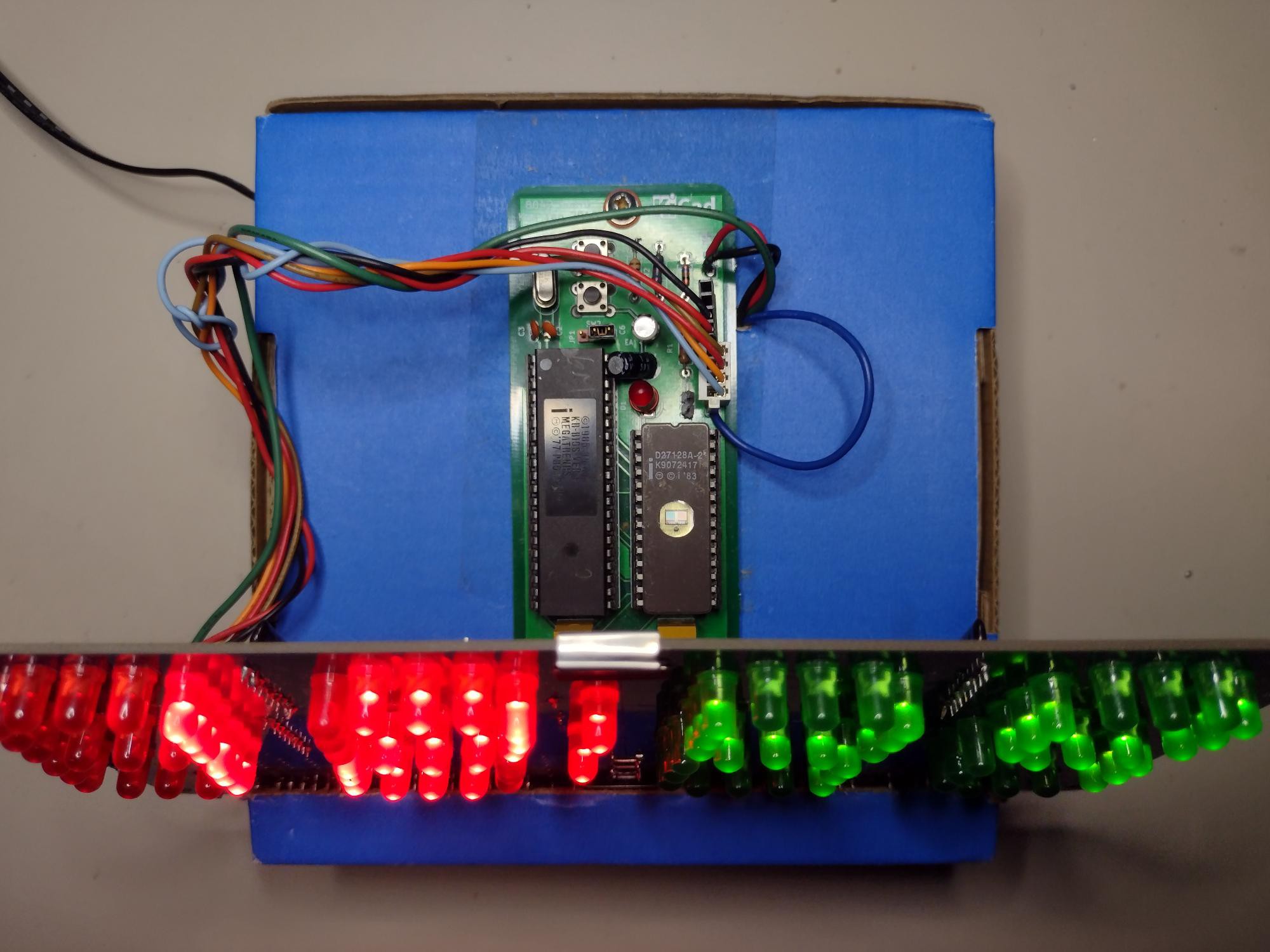
I think I now have a use for them. I cut a slightly slanting slot about 15° from the vertical from the top a few cm down the sides. Then I mounted quite recently designed boards from #Ancient 12 hour display there. The box is actually turned upside down and back to front, hence the discreet upside down logos on the front.
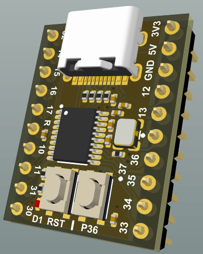
Here is the top view with the MCU module, although any MCU module will do. It's mounted outside because of the setting buttons. The power supply board is inside. It's supplied from a wall wart so low voltages.

I'll need to judiciously apply some hot glue to prevent joints and wires from going astray. Also to secure the clips at the middle top and bottom.
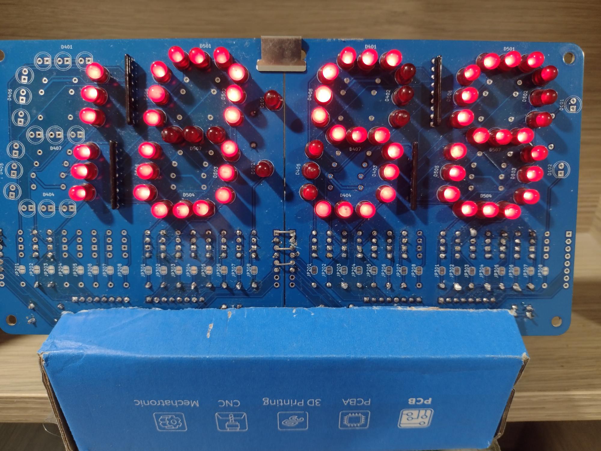
Another box. This is the clock from #Ancient 12 hour display

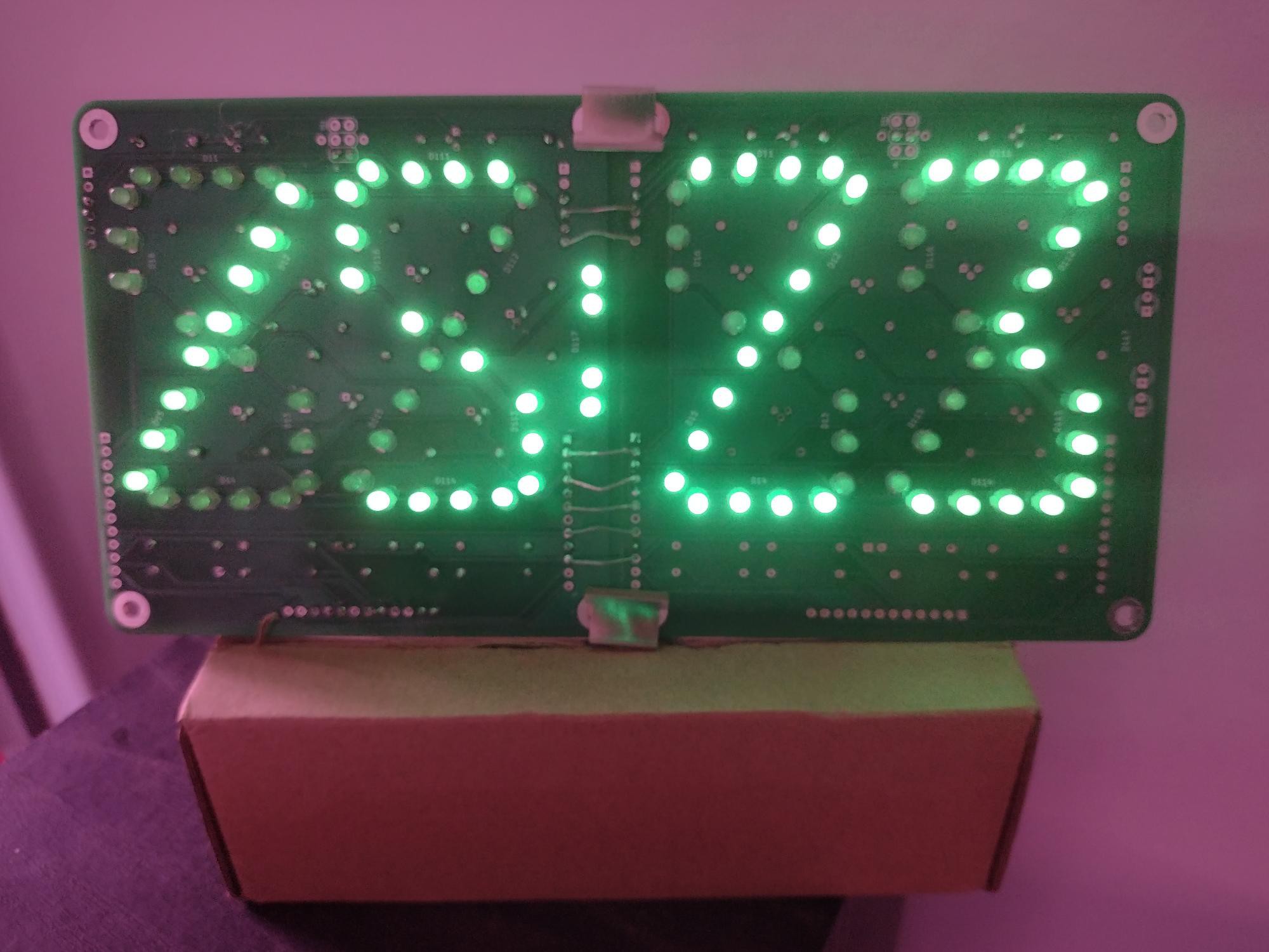
Yet another box. Though strictly speaking this is not from JLCPCB but from another PCB fabricator.

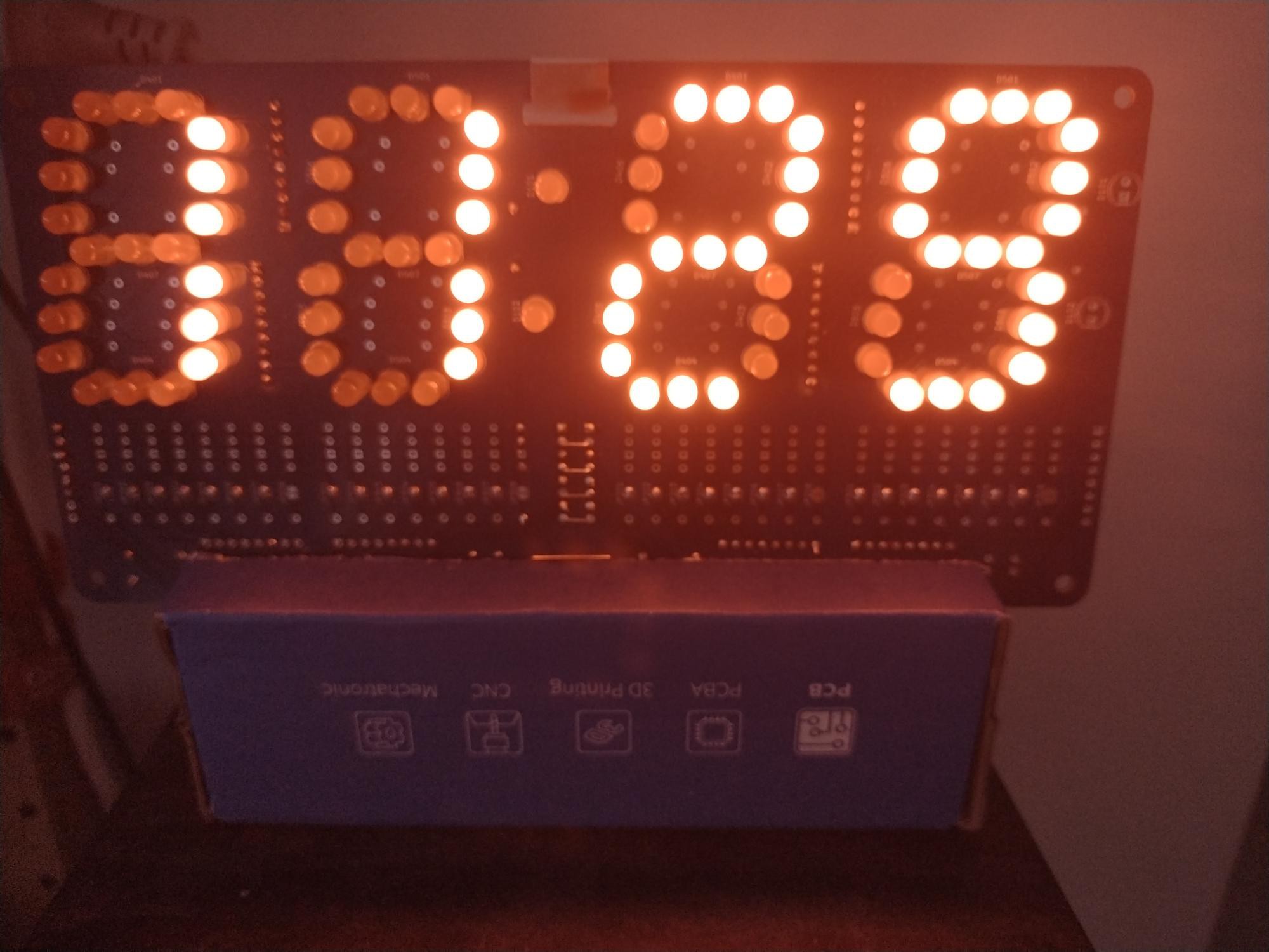
It's extremely difficult to show in a picture, but the colour of light from orange LEDs resembles that of nixies for those wanting that warm glow.

This project was not sponsored by JLCPCB. But I still thank them for the boxes. 🤣
-
The two button mode-set UI
03/14/2025 at 22:01 • 1 comment
The two button mode-set user interface is a design to allow changing many settings with only two buttons. It is used in many devices, even my ancient Casio F91-W watch from 45 years ago used it. Here is a simple example used in a 4 digit clock:
Indication Button 1 Button 2 Notes Normal display Time displayed Go to set hour Leaving normal display may require holding down the button for a while so that it's hard to activate accidentally Set hour Hour displayed Go to set minute Advance hour Set minute Minute displayed Go to set brightness Advance minute Set brightness All 8s displayed Go to normal display Change brightness In some implementations pressing both button 1 and 2 together does this As you can see, button 1 loops through the various modes, and button 2 is an increment button, which also loops on wrap around. Sometimes a third button is provided to decrement the counter, but I feel this detracts from simplicity. With autorepeat it doesn't take long to wrap around anyway.
Notes
- The advance will wrap around appropriately.
- Holding down button 2 will after 0.4 seconds, autorepeat at 4 times per second.
- The hidden seconds counter is set to zero whenever the minutes are advanced. To synchronise the time to a reference clock, set the minutes to the current minute. When the minute ticks over on the reference clock, click once on button 2.
- If the mode is not at normal display, it will revert to normal display after 64 seconds of button inactivity.
By contrast, the clock chips from National Semiconductor used a multi-button scheme. On the MM5316, I count: Fast set, Slow set, Seconds display, Alarm display, Sleep display, Alarm off, and Snooze. Fast set and slow set require estimating how close one is to the target to change buttons instead of setting the relevant counter directly. A bedside clock has room for more buttons, but I feel that there are too many buttons.
Here is a more elaborate example where the clock stores the date also. Let's put aside how or when the date is displayed. It could be alternately with the time as some old clock chips did, or a separate display:
Indication Button 1 Button 2 Notes Normal display Time displayed Go to set hour Set hour Hour displayed Go to set minute Advance hour Set minute Minute displayed Go to date Advance minute Date Month and day displayed Go to set month Set month Month displayed Go to set day Advance month Set day Day displayed Go to set brightness Advance day Set brightness All 8s displayed Go to normal display Change brightness Here is another elaborate example for an alarm clock radio with sleep timer which is turned on by an alarm match, or by manually setting to non-zero. Notice that button 2 has a function in normal display mode:
Indication Button 1 Button 2 Notes Normal display Time displayed Go to set hour Turns off alarm by zeroing sleep timer Set hour Hour displayed Go to set minute Advance hour Set minute Minute displayed Go to alarm time Advance minute Alarm time and status Alarm time Go to set alarm hour Toggle alarm Colon indicates if alarm active Set alarm hour Alarm hour displayed with steady colon Go to set alarm minute Advance alarm hour Set alarm minute Alarm minute displayed with steady colon Go to set sleep minute Advance alarm minute Set sleep minute Sleep minute displayed without colon Go to normal display Decrease sleep minute If at zero, will wrap around to 59 and turn on alarm (sleep output) The alarm is actually the radio, whose power is switched by the sleep output, doing double duty as an alarm and a sleep radio. Notice that we arrange it so that the display also indicates which mode it is in, to avoid having more indicators. This is not so important when the display technology can provide indicators, like LCDs, and LED raster displays.
The implementation is quite straightforward. It consists of a switch statement for both buttons, and a switch statement for button 2:
static...Read more -
Another skirmish with the avr-gcc toolchain
03/09/2025 at 06:02 • 0 comments
Wow, it's been almost 5 years and one pandemic since I tried to do something with this chip, first by installing, or rather piggybacking on, the gcc-avr toolchain. This MCU is pin compatible with the 8051 except for the polarity of the reset pin. I tried to get it working in the dev board in #Adventures with a STC89C52 development board but no joy.
Today I decided to try to get it working (or determine that it's bust) once and for all. I flashed a clock program onto it and watched the voltages on the port pins. All high. But the oscillator pins seemed to be ok. Time to look at my firmware.
Disassembling the .elf file with avr-objdump showed the start of the executable area:
Disassembly of section .text:

00000000 <__ctors_end>:
   0:   11 e0           ldi     r17, 0x01       ; 1
   2:   a0 e6           ldi     r26, 0x60       ; 96
   4:   b0 e0           ldi     r27, 0x00       ; 0
   6:   ea ef           ldi     r30, 0xFA       ; 250
   8:   f6 e0           ldi     r31, 0x06       ; 6
   a:   03 c0           rjmp    .+6             ; 0x12 <__zero_reg__+0x11>
   c:   c8 95           lpm
   e:   31 96           adiw    r30, 0x01       ; 1
  10:   0d 92           st      X+, r0
  12:   ac 32           cpi     r26, 0x2C       ; 44
  14:   b1 07           cpc     r27, r17
  16:   d1 f7           brne    .-12            ; 0xc <__zero_reg__+0xb>

00000018 <__do_clear_bss>:
  18:   21 e0           ldi     r18, 0x01       ; 1
  1a:   ac e2           ldi     r26, 0x2C       ; 44
  1c:   b1 e0           ldi     r27, 0x01       ; 1
  1e:   01 c0           rjmp    .+2             ; 0x22 <.do_clear_bss_start>

00000020 <.do_clear_bss_loop>:
  20:   1d 92           st      X+, r1

00000022 <.do_clear_bss_start>:
  22:   a9 34           cpi     r26, 0x49       ; 73
  24:   b2 07           cpc     r27, r18
  26:   e1 f7           brne    .-8             ; 0x20 <.do_clear_bss_loop>

00000028 <__vector_4>:
  28:   1f 92           push    r1
  2a:   0f 92           push    r0
  2c:   0f b6           in      r0, 0x3f        ; 63
  2e:   0f 92           push    r0
  30:   11 24           eor     r1, r1
  32:   8f 93           push    r24
  34:   80 91 37 01     lds     r24, 0x0137     ; 0x800137
  38:   81 50           subi    r24, 0x01       ; 1
  3a:   80 93 37 01     sts     0x0137, r24     ; 0x800137
  3e:   8f 91           pop     r24
  40:   0f 90           pop     r0
  42:   0f be           out     0x3f, r0        ; 63
  44:   0f 90           pop     r0
  46:   1f 90           pop     r1
  48:   18 95           reti
Ah, that's no good. Although the code starts at 0, the next few locations should be interrupt vectors. In particular there should be an entry for vector_4, the timer vector. The code clears the BSS, but doesn't set up the PSW and the SP; one would expect some out 0x3[def] instructions. It doesn't call main, but falls through to vector_4, the first routine in the main C program.
We need more than this. Arduino users of the AVR chips have a startup environment that calls setup(), then loop() repeatedly. When doing bare metal (bare silicon?) stuff, like I am there should be startup code. Unfortunately a search on bare metal AVR got lots of pages explaining how to do direct I/O to ports, bypassing pinMode() and digitalWrite(), that's their idea of bare metal. The closest I found was this post on StackOverflow.
Ok so I need the equivalent of what has been known since Unix days as crt0.s, the assembly code for the startup code for C programs. A bit of searching in the avr-gcc directories found crtat90s8515.o. No corresponding .s, but that's ok, I can disassemble it with avr-objdump. It's probably in the source distribution.
Adding crtat90s8515.o to the list of linker input files gets this disassembled code:
Disassembly of section .text:

00000000 <__vectors>:
   0:   0c c0           rjmp    .+24            ; 0x1a <__ctors_end>
   2:   27 c0           rjmp    .+78            ; 0x52 <__bad_interrupt>
   4:   26 c0           rjmp    .+76            ; 0x52 <__bad_interrupt>
   6:   25 c0           rjmp    .+74            ; 0x52 <__bad_interrupt>
   8:   25 c0           rjmp    .+74            ; 0x54 <__vector_4>
   a:   23 c0           rjmp    .+70            ; 0x52 <__bad_interrupt>
   c:   22 c0           rjmp    .+68            ; 0x52 <__bad_interrupt>
   e:   21 c0           rjmp    .+66            ; 0x52 <__bad_interrupt>
  10:   20 c0           rjmp    .+64            ; 0x52 <__bad_interrupt>
  12:   1f c0           rjmp    .+62            ; 0x52 <__bad_interrupt>
  14:   1e c0           rjmp    .+60            ; 0x52 <__bad_interrupt>
  16:   1d c0           rjmp    .+58            ; 0x52 <__bad_interrupt>
  18:   1c c0           rjmp    .+56            ; 0x52 <__bad_interrupt>

0000001a <__ctors_end>:
  1a:   11 24           eor     r1, r1
  1c:   1f be           out     0x3f, r1        ; 63
  1e:   cf e5           ldi     r28, 0x5F       ; 95
  20:   d2 e0           ldi     r29, 0x02       ; 2
  22:   de bf           out     0x3e, r29       ; 62
  24:   cd bf           out     0x3d, r28       ; 61

00000026 <__do_copy_data>:
  26:   11 e0           ldi     r17, 0x01       ; 1
  28:   a0 e6           ldi     r26, 0x60       ; 96
 2a: b0 e0...
Read more -
LED bargraph clock?
02/26/2025 at 07:34 • 4 comments
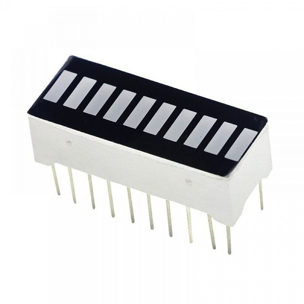
I found that I have a couple of LED bargraph displays in my junk box. They are the old-fangled single colour type, not even the multi-coloured type used for battery charge indicators, level indicators and the like. They were intended to be driven by the LM3914 IC. That chip can be configured for dot mode or bar mode.
At the moment I don't have anything I need to display the level of. But since the display contains 10 discrete LEDs, I wondered if I could make a 10-bit display out of it. Let's see, for a binary clock, 0-59 minutes need 6 bits, and 0-23 hours need 5 bits. Oops. Maybe a 12 hour clock, and look out the window to see if it's AM or PM. 😉
It would be trivial to wire up to a MCU and get working, but nah, I'll pass on this one. The display would be too small, straining my eyes. It's bad enough having to mentally decode the binary. I know most of my projects are useless, but this is even more useless than usual. 🤪 Just setting down the idea for my amusement.
-
Tweaking a protothreads button handler
02/11/2025 at 05:49 • 0 commentsI have written on protothreads for switch handling in the past, as a log in a 8051 project of mine, but a recent modification that I wanted to do put protothreads in my mind again so I decided to rewrite it as a page.
Interface handling usually involves keeping track of the state. The changes in state are at human pace so waiting is not feasible as the MCU has other tasks to do. An example is switch debouncing and autorepeat.
You could do it with a full fledged thread facility. Or the programming language may offer coroutines, like Lua. In other languages usually the programmer resorts to writing a state machine, where variables remember where the subtask is up to. Sometimes the state machine uses an explicit state variable, sometimes the state is encoded in the values of variables.
But state machine code can be hard to comprehend. So I thought there should be a solution with very lightweight threads. A search found Protothreads by Adam Dunkels which has been available since 2005. This is designed for low resource MCUs, only requiring one integer location to store the thread state. It is implemented in standard C, not requiring any assembler assist, so is portable to any MCU with a suitable C compiler. In fact the C code consists of preprocessor macros.
Here's an example of the code I reuse unchanged in many of my projects. The requirements are:
- When a button is pressed the thread waits until the debounce period has passed. If the button is released before this, i.e. it was just a temporary spike, the thread restarts.
- On expiry of the debounce period, the action is taken. The thread then waits until the autorepeat threshold is reached. If the button is released before this, the thread restarts.
- On expiry of the autorepeat threshold, the action is taken. The thread then repeatedly waits for the repeat period to elapse, taking the action every time this happens. If the button is released at any time, the thread restarts.
Note that swstate and swtent (tentative state) are actually bit vectors representing an array of switches, so this code handles more than one switch. The code that corresponds to each switch is called from switchaction(). To make things concrete, this design uses a debounce period of 100 ms, an autorepeat threshold of 400 ms more, and a repeat period of 250 ms (4 times a second).
static inline void reinitstate()
{
        swtent = swstate;
        swmin = DEPMIN;
        swrepeat = RPTTHRESH;
}

static
PT_THREAD(switchhandler(struct pt *pt, uchar oneshot))
{
        PT_BEGIN(pt);
        PT_WAIT_UNTIL(pt, swstate != swtent);
        swmin = (swstate == SWMASK) ? DEPMIN : RELMIN;
        swtent = swstate;
        PT_WAIT_UNTIL(pt, --swmin <= 0 || swstate != swtent);
        if (swstate != swtent) {                // changed, restart
                reinitstate();
                PT_RESTART(pt);
        }
        switchaction();
        if (oneshot) {
                reinitstate();
                PT_RESTART(pt);
        }
        PT_WAIT_UNTIL(pt, --swrepeat <= 0 || swstate != swtent);
        if (swstate != swtent) {                // changed, restart
                reinitstate();
                PT_RESTART(pt);
        }
        switchaction();
        for (;;) {
                swrepeat = RPTPERIOD;
                PT_WAIT_UNTIL(pt, --swrepeat <= 0 || swstate == SWMASK);
                if (swstate == SWMASK) {        // released, restart
                        reinitstate();
                        PT_RESTART(pt);
                }
                switchaction();
        }
        PT_END(pt);
}
You can see that it is programmed as a sequential routine. The structure of the handler mirrors the specification above. You have to imagine that the thread has a life of its own and waits at the PT_WAIT_UNTIL macro until the condition is satisfied. In reality, the MCU exits the routine and uses a local continuation to know where to restart when the thread is called again. It's really thinly disguised state machine code, but written like sequential code.
Unlike a real thread library, there is no scheduling. You have to arrange to periodically call the thread handler.
Now the modification that I wanted was to have a shorter debounce time for depress than release. The change turned out to be trivial:
diff --git a/clock.h b/clock.h
index 9701dfb..db74d57 100644
--- a/clock.h
+++...
Read more -
Stitching boards with paper clips
01/11/2025 at 09:44 • 0 comments
People who follow my display board projects know that I usually design them to be cascaded for more digits. They are connected in series using either Dupont pin sockets and pin headers, or just soldered jumpers as in the photo above. Neither is satisfactory as there is still flexure. I have considered using small aluminium straps and screws to hold the boards together stiffly using the corner holes. But I would have to look for aluminium strip of the right width and hacksaw small lengths off.
Today I tried another idea, using reusable paper clips that were designed to hold multiple sheets of a document together. They are attached to a corner of the document stack with a special tool. It's a solution between standard paper clips and fold back paper clips.

It works and I would also need to put some hot glue on the clips to prevent them from sliding off. However in future I will also need to design enough clearance so that the clip doesn't short PCB connections as the one on top in the picture almost does.
-
A buglet initialising the CH552
01/05/2025 at 00:08 • 0 comments
When I finally put the two boards described in Flashing the CH552 dev board from the command line to use I noticed that button actions were faster. Counter advance worked twice as fast. The no-activity timeout for exiting set mode was 32 seconds instead of 64. At boot-up the MCU runs at 24 MHz, but this can be set to 12 MHz for compatibility with the classic 8051. The tick timer which governs the speed of button actions depends on the clock speed.
I thought I had taken care of this in the initialisation code, but to cut to the chase, here's the diff showing what I did wrong:
$ git diff 227da07..67b402a
diff --git a/227da07 b/67b402a
index 227da07..67b402a 100644
--- a/227da07
+++ b/67b402a
@@ -200,8 +200,7 @@ void main(void)
        // change the clock divisor to generate 12 MHz
        SAFE_MOD = 0x55;
        SAFE_MOD = 0xAA;
-       CLOCK_CFG &= ~CLOCK_DIVISOR;
-       CLOCK_CFG |= CLOCK_DIVISOR;
+       CLOCK_CFG = (bOSC_EN_INT | CLOCK_DIVISOR);
        SAFE_MOD = 0x00;                // any value will do
 #ifdef DEBUG
 #else
The clock configuration register is protected against accidental modification by a protocol. You have to write the values 0x55 and 0xAA to the SAFE_MOD register, make your change, then exit by writing anything to SAFE_MOD. The intention of the original code was to read the bits in the CLOCK_CFG register, except for the CLOCK_DIVISOR (bottom 3) bits, then write it back with those bits modified. You can see that the first line ought to be:
CLOCK_CFG &= (0xF8 | ~CLOCK_DIVISOR);to preserve the top 5 bits.
But I also fell foul of another restriction and that is modification mode only lasts for a limited number of clock cycles. More instructions and the changes don't take. That was probably what was happening, it timed out before CLOCK_CFG was changed. So I just went for a simple one line replacement and that fixed the double speed problem.
BTW, I prefer to run the MCU at a lower clock rate rather than recalibrate the timer for a faster clock. It's more reliable at lower clock rates, and the MCU is idle most of the time anyway.
-
Recording Internet radio with a Raspberry Pi 2B
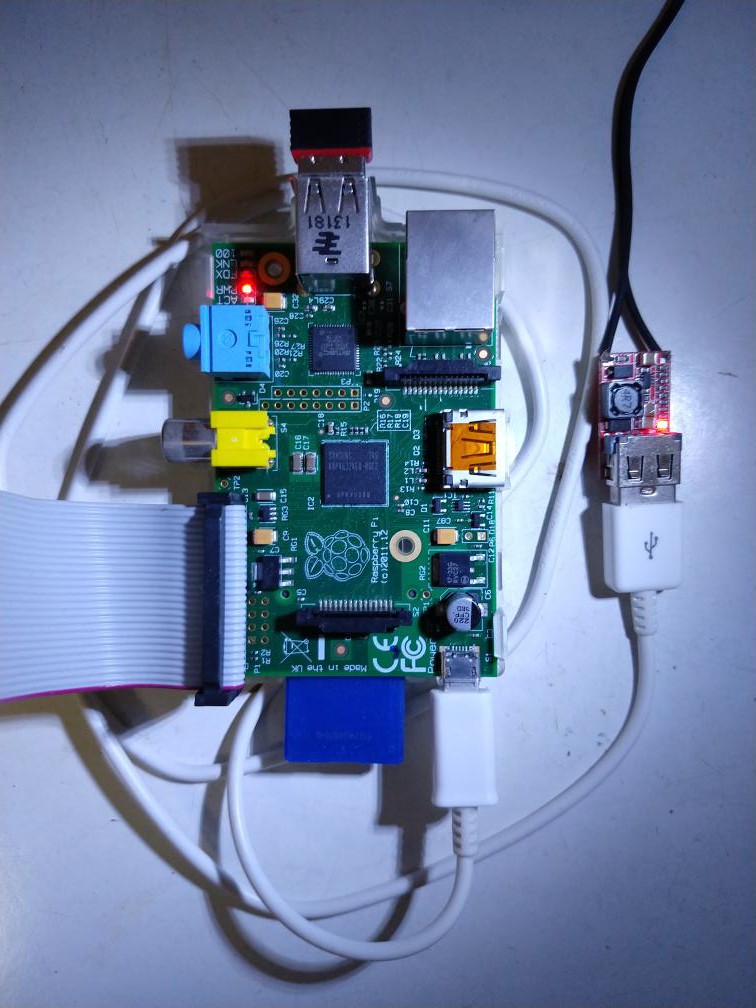
01/04/2025 at 07:42 • 0 commentsInternet radio is great, you can listen to stations all over the world. You may wish to save some programs. I have been doing this for a while from my Linux workhorse. I recently looked into doing this from an ancient Raspberry Pi 2B. It took a couple of battles with the DietPi distro and the mplayer packages, but it's done. Here are the articles I wrote in my technical blog:
-
A tale of DS1287s
11/27/2024 at 12:11 • 0 comments
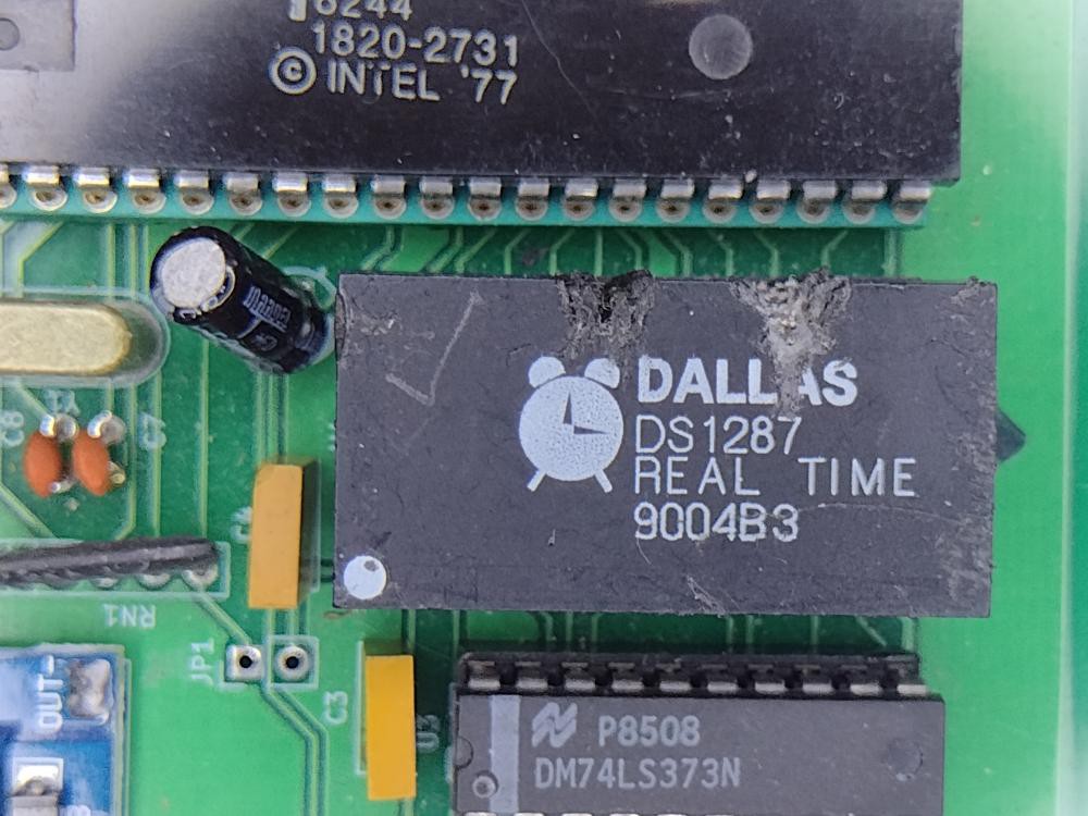
Among the junk in my box are a handful of RTC modules scavenged from old PCs. They are the DS1287 and DS12887 from Dallas Semiconductor which are basically the Motorola MC146818 with a 32.768 kHz crystal and coin cell attached and encapsulated in a tall 24 pin DIP package.
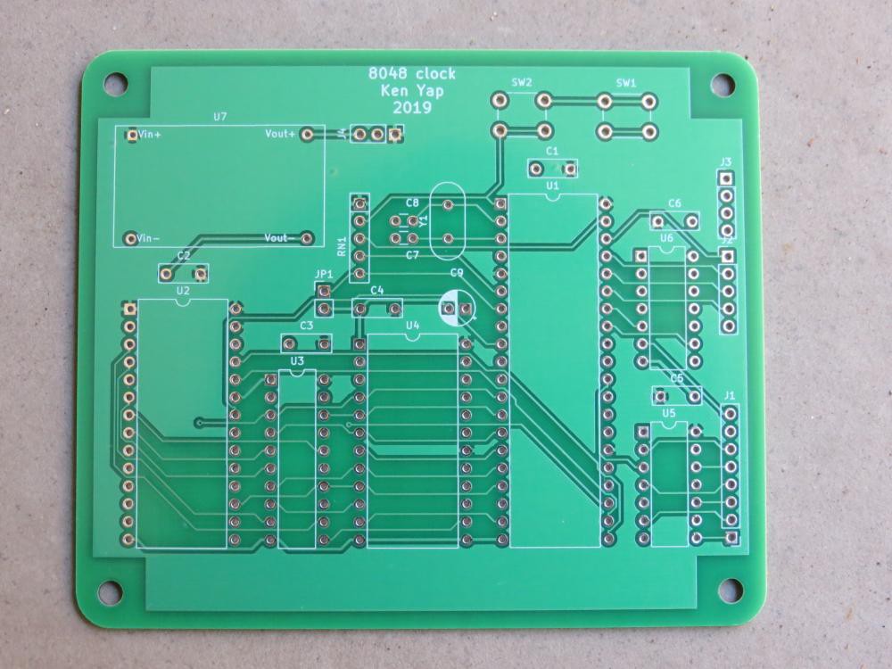
Of course the coin cell drained long ago, so I applied this rework hack (with a hacksaw too, you can see the notches in the photo above) to disconnect the cell. I had incorporated a socket for this RTC in my 8048 board and written firmware for it. You see a section of the board in the photo above. The idea was that if I powered the RTC module with an external battery it could maintain time without power. This was not successful. Only some of the RTC modules could be made to work, and not very reliably, even when powered by the same 5V supply as the 8048 microcontroller.
Finally with curiosity killing me I decided to get to the bottom of matter. I wrote an Arduino sketch to initialise the RTC (basically the same sketch I used to test the freestanding MC146818s I had) and then read the time registers. I also enabled the SQW (square wave) output of the chip and attached a scope to that output.
What I discovered was that only a few of the modules I had could keep updating the time registers and also provide a 32 Hz square wave output. A few couldn't update the registers but could supply the SQW.
So I tossed out 2 modules that couldn't even generate a SQW, obviously the crystal oscillator or MC146818 inside were bust. For the remaining ones I modified the board and firmware a little to use the SQW as a pseudo-mains timebase, and set the clock going. The 2 DS12887s and 1 of the 3 DS1287s were a bit erratic, and sporadically stopped oscillating. That left only 2 usable DS1287s. But they kept pretty good time only a few seconds out per week, considering they are an old generation of RTCs, whereas the current generation has temperature and ageing compensation. This may be because they are running indoors where the temperature only varies a couple of °C around 24°C.
So I now know that I have 2 usable modules for my boards. The rest I can send to e-waste heaven.
-
Time to ditch the 2764s
11/08/2024 at 06:25 • 0 comments
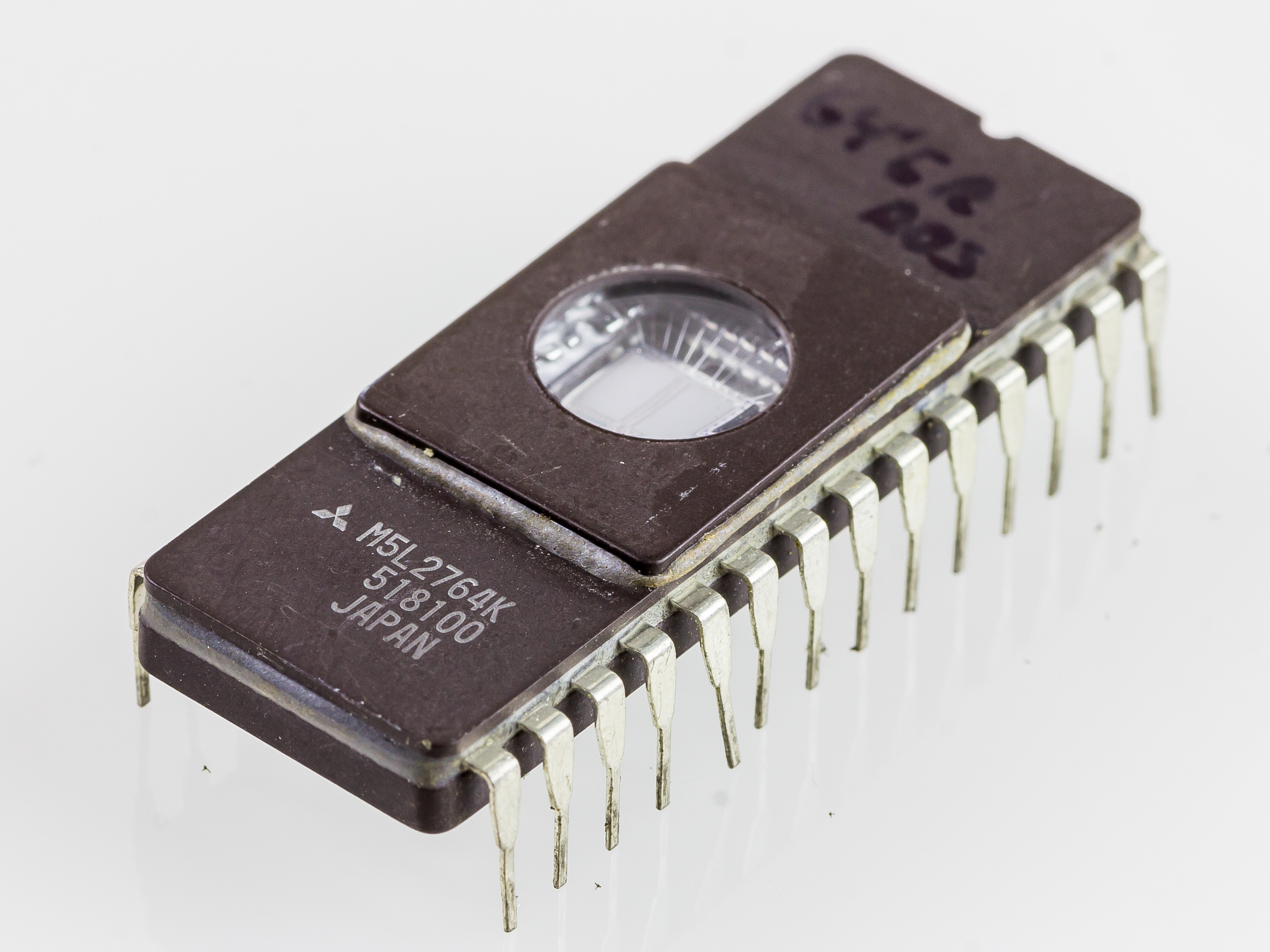
© Raimond Spekking / CC BY-SA 4.0 (via Wikimedia Commons), Mitsubishi M5L2764K-5377 , CC BY-SA 4.0
After creating a minor tweak to the firmware for #8042 clock (the PCB version, the breadboard version was disassembled years ago) I needed to burn some 2764 EPROMs with my trusty TL866A. Unfortunately some of the EPROMs couldn't be programmed, but others could. The common factor seemed to be the need for 21V Vpp. Usually the C (for CMOS) chips could be programmed.
I had been able to program these in the past so either my TL866A had developed a fault or the open source minipro software for Linux had a bug. I couldn't find any reports about this in the repo, so that would point to the former. Or hardly anybody programs 21V Vpp EPROMs any more so never hit a bug.
I had already written about ancient 2[57]{16,32} EPROMs that require 25V Vpp, and had concluded that I would not be able to use them. So for these 21V Vpp 2764s, I think the most expedient way forward for a lazy cat is not spend time working out whether my programmer or the minipro software is at fault, or even trying the Windows minipro software in a VM, but just bin these chips. (Or if anybody wants them for the cost of postage, PM me.)
Fortunately my designs already cater for using 27C128 or even 27C256 EPROMs in the same 28-pin socket, and I still have a lot of those, probably more than I'll ever be able to use up, as I'm more ancient than the chips. And anyway the non-CMOS versions of the 2764 are more power-hungry.
-
Assembling a 120 W bench power supply
10/20/2024 at 19:38 • 4 comments
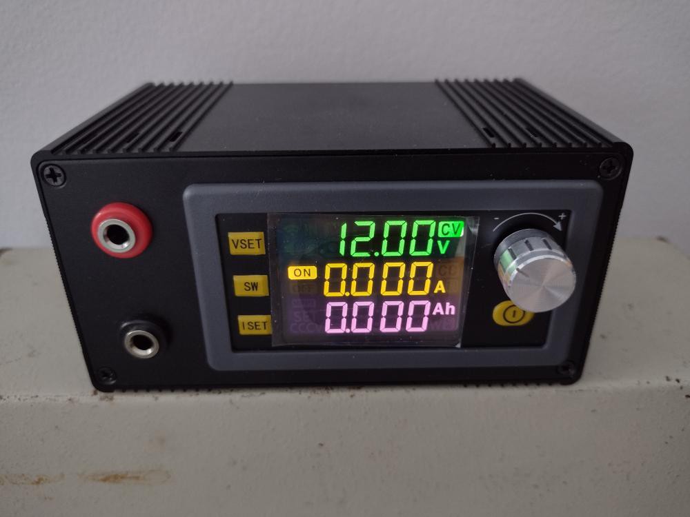
I ordered a XY-SK120 buck-boost converter with digital controller with LCD screen from Aliexpress. With it I can dial up any desired voltage and use current limiting to forestall damage when first powering up projects. It has many other features. From the specs it's quite an impressive piece of electronics for its small size. Input can be 6-36 VDC and output 0-36 VDC at up to 6 A and it handles up to 120W.
I chose the cased version. It's more than just the bare converter board with banana sockets in an enclosure. At the back is a cooling fan and a power input panel that takes various sources, including terminal block, barrel socket, some kind of Molex socket, and even USB-3 PD input. A cursory inspection shows that diodes isolate the inputs from each other. These extras account for the higher price.
The fly in the ointment is poor documentation. It would be nice to know how to operate the UI without trial and error. Not even a slip of paper in the box. But a bit of hunting found an instruction manual online. From the modification date, less than 3 months ago, the firmware is still being improved, and in the future it might be possible to update it using the serial interface.
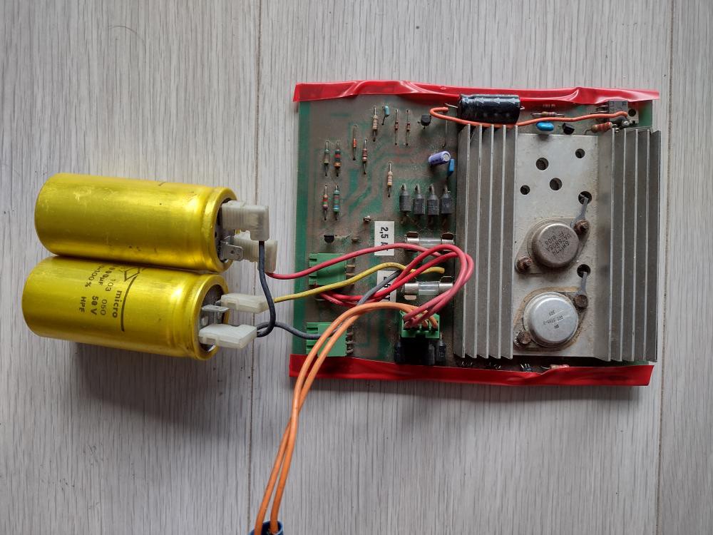
Normally one would use a SMPS or an old laptop power brick for the input. I decided to put to use an old school power supply board possibly from an LA30 Decwriter that the board for #Flashing LEDs from old printer electronics came from. In the board pictured below, only one set of bridge rectifiers and one large capacitor are in use. There are actually two independent power supplies on the board. The low voltage one supplies digital logic via a 5 V regulator, one of the large TO-3 cases. I won't be using that half. The high voltage one supplies the electromechanics. The capacitor is a whopping 10000 µF rated for 50 V so lots of margin. Nominal voltage level was probably around 30 V. A 24 VAC appliance transformer that I was given feeds the board.

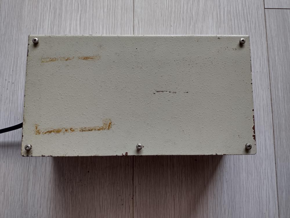
For the enclosure I used an old Ryobi timer saved from e-waste. It seems to have been an appendage to unknown industrial equipment. The inside was gutted to fit the PS PCB.

That such a small controller can provide 6 A is a testament to how much the power density of electronics has increased over the years. (But some reviews mention that the cooling fan may be inadequate at high power levels.) The current is more than the old bulky linear power supply can supply. The fuse on the rectifier board is rated at 2.5 A. The transformer is rated at 1.5 A. (Although at lower output voltage, more current can be supplied, as the converter is switching mode.) Anyway this is enough for my needs for the near future.
Oops, I forgot to order 4 mm banana plug cables. Next round then. Can't buy everything in the shops all at once. 😉
Well that takes another tuit off my round tuit list.
-
Simple opamp tester
09/26/2024 at 11:07 • 0 comments
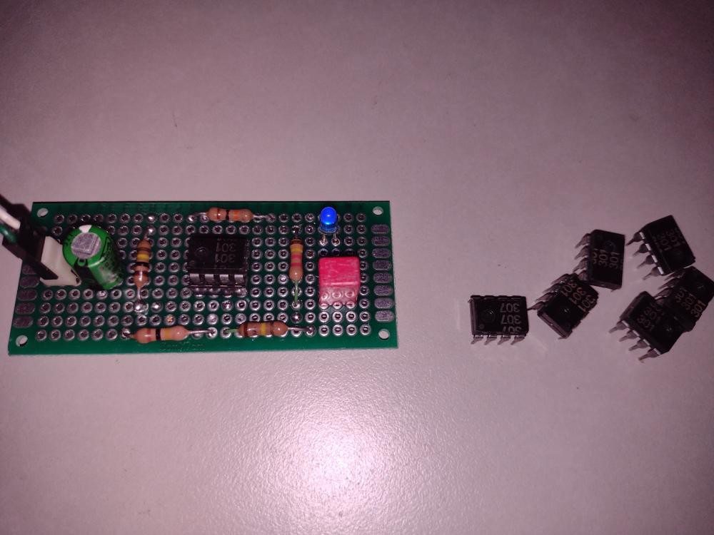
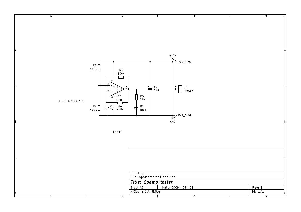
I have many 8-pin opamp ICs such as the venerable 741 in my junk box, some pulls, some from grab bag purchases. I wondered how many of them are working. So I put together a simple circuit to check basic opamp function. I assembled it on perfboard as it's a simple circuit and I only need one.

It's a familiar relaxation oscillator. Normally we need balanced voltage rails for an opamp, but the resistor network R1, R2, and R3 establish upper and lower bounds of roughly ⅓ and ⅔ the supply voltage. The values chosen make the LED to blink at about 3 Hz. The pin numbers are for the 741 and others with the same pinout. It's just a go-nogo check and doesn't test advanced characteristics. The tester found a handful of duds which I can now throw out. So if nothing else, I know that I have lots of blinky ICs in my collection. 😉
-
Trying out JLC's 3D printing service
08/02/2024 at 08:56 • 1 comment
Since JLCPCB lowered its shipping charge to $1.50 for small parcels to me, I wondered if the same applied to JLC's other services. I decided to try out their 3D printing service.
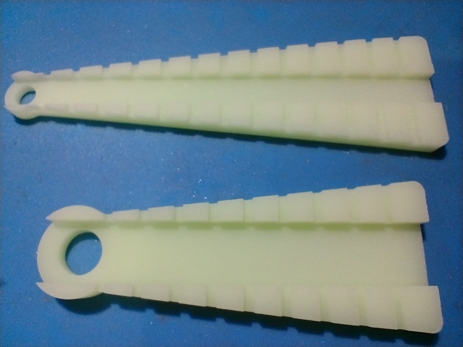
I have wanted a THT resistor lead former for a while. It helps make sure the leads are the right spacing for insertion into PCB holes. But even manufactured ones on Aliexpress cost several dollars each. Daylight robbery for a piece of plastic. I guessed that there would be open designs available and sure enough I found dnewman's design on Thingiverse. I ordered both narrow and wide Imperial size models.
Submission through the web form was straightforward but even just for SLA I was bewildered by a plethora of choice of resin material. A friend explained that they were simply different resins for different use cases. In fact tooltips on the options explain what each is good for. Since the part in question is not load bearing, doesn't have to withstand heat, and doesn't have to be a particular colour, I went for the cheapest beige resin. But even other resin types would not have broken the bank. The order came up to $2.70 including shipping.
There was a bit of a hitch when their engineer warned me about a thin wall < 0.8 mm in the design. It's near the narrow end of the skinny former. I think it means that this feature is in danger of breaking off. I don't have the skill to edit the source files of the design and this isn't a critical part so I told the engineer to let it through.
Progress through production wasn't as fast as for PCBs. I think they don't work on weekends. But there are less steps and it was done in a couple of days then shipped.
This is a cheaper way to get 3D printing done than at my local library where there is a printer, provided I'm willing to wait 10-14 days.
-
MC14450, a tiny chip from half a century ago
07/13/2024 at 10:46 • 0 comments
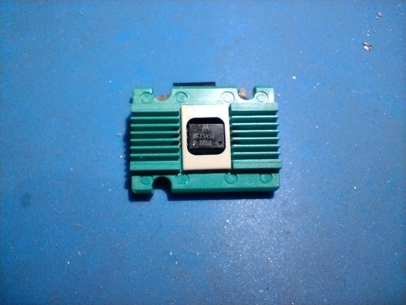
Rummaging through my
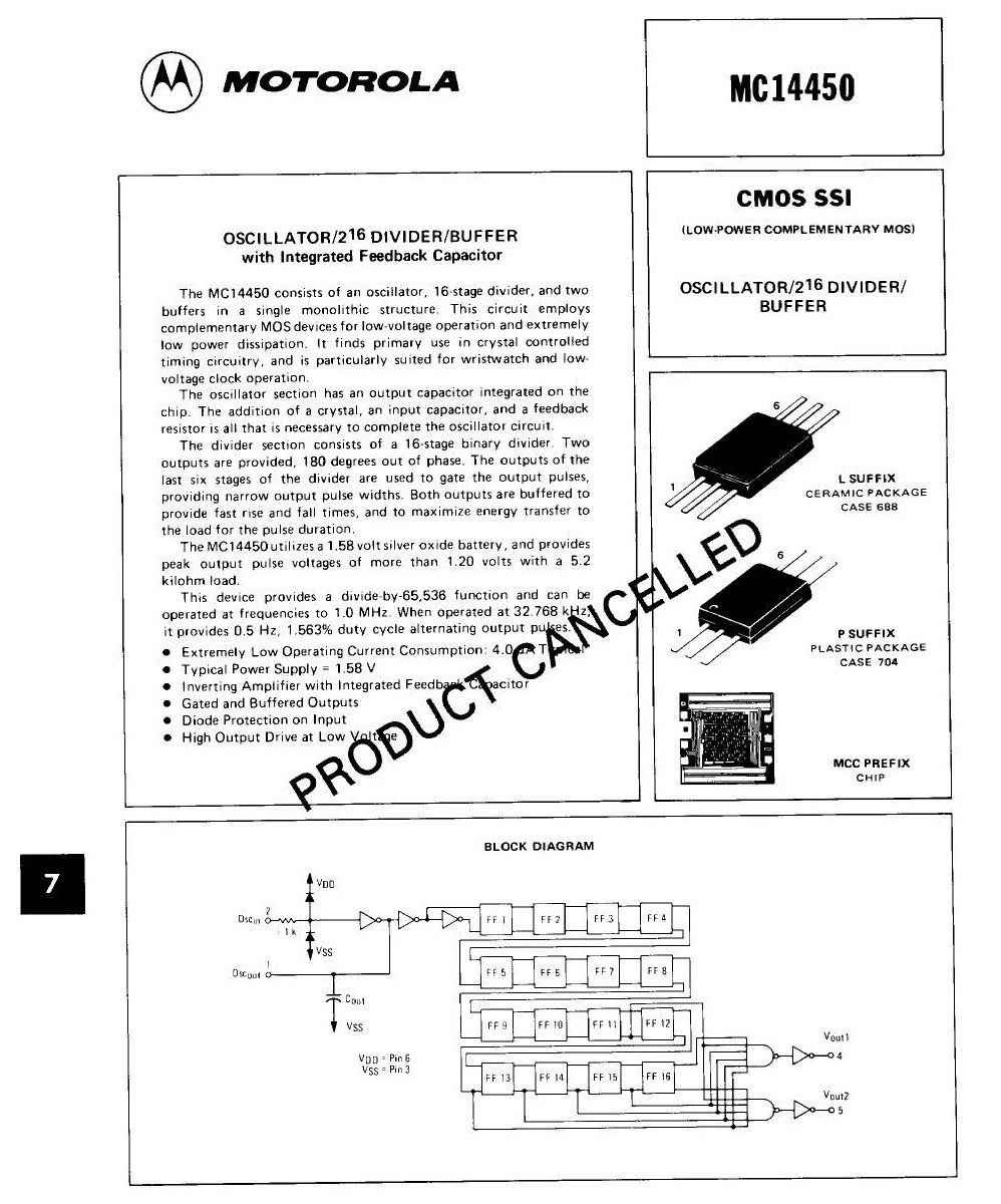
junkspare parts box, I found this tiny 6-pin chip in a carrier. Curious, I looked it up and here's the first page of the datasheet.
It is an oscillator and 2^16 divider, from 32768 Hz to ½ Hz, intended to be used in quartz timebase watches with mechanical hands which explains the tiny package and leads. The date code indicates it was produced the 50th week of 1976. An interesting aspect is it runs on 1.5V from a silver oxide cell and at no more than 3.0V.
Oh well, not much use for this almost 50 year old chip except to write a blog page about it. 😉
-
Getting blinky working on the WCH CH32V003F4 development board
07/03/2024 at 10:53 • 2 comments
Motivation
I decided to dip my toes into the current generation of cheap RISC-V MCUs under 20¢ each. The QingKe CH32V003 looked like a good candidate for a basic workhorse MCU. I have some MCUs from the ARM Cortex family like the STM32 and RPI2040 but I have a preference for an open ISA as I think this will drive prices down. I had tried out the GD32V Longan Nano but that was too expensive. The W806 looked promising but that used the Csky architecture which is manufacturer specific, and not much has been heard from them since.
Note that WeActStudio has got into the RISC-V game with the CH5[789]x which can in fact use the same toolchain as the WCH products. The ESP32-C3 is also RISC-V based and of course comes with WiFi and Bluetooth support.
I'm actually late to the game; there are lots of projects on HaD and on the Internet already using the CH32V. I just want to document my initial experiences and maybe help others avoid pitfalls. I'm on Linux but many details are similar on other host OSes.
Ordering
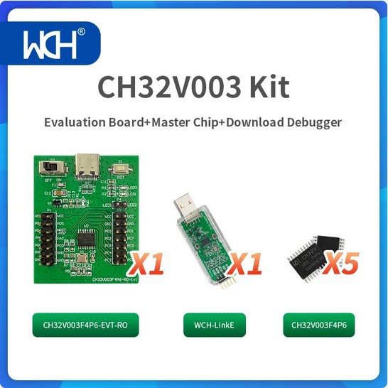
I ordered the kit pictured above for about $10 from the WCH official store on AliExpress which guaranteed me that I would be getting the correct combo. You need the WCH-LinkE to start off, despite any webpages out there talking about programming using the USB-C port. That can only be done if you have installed a bootloader that listens to the USB-C port. Also do not buy the older WCH-Link without the E, it cannot program the 00x series.
Setup
Both Arduino and PlatformIO have support for CH32V. Arduino uses the official gcc 8.2 toolchain and an open source OpenOCD for downloading. PlatformIO uses the xpack distribution of the same software. Later I will explore using command line tools instead of an IDE for development, but it's useful to see what commands an IDE is issuing behind the scenes.
After installing either or both IDEs, there are a couple of udev rule files you need to copy to /etc/udev/rules.d so that you have access to the USB device as an ordinary user (do not do development as root!). You can find them under the openocd directory in either IDE. I had to change the group from plugdev to dialout for my distro. Yeah, it's historical.
Now plug in the WCH-LinkE and you will see a new USB device appear. In my case the device was /dev/ttyACM0.
Instructions say you need to connect GND, 3V3 and SWDIO on the dongle side to GND, VCC, and PD1 on the dev board side. This required a 3 wire pin socket cable which was not included. I found a 4 wire cable from PC days, and fortunately the wires are in the same order on both ends, and 4th pin socket was off the end of the connector pad and didn't connect to anything.
Testing
I fired up the Arduino IDE and selected the CH32V00x target and /dev/ttyACM0 port. I could then get the board info and this showed me the MCU ID in addition to the USB IDs.
I loaded the blink sketch from Examples, compiled and downloaded it. But nothing blinked. I found out from a tutorial that the 2 onboard LEDs are not connected to any port pin. I guess this gives flexibility for development and debugging later. So I had to find another pin socket jumper wire. Which port pin should I connect it to though, in other words what does LED_BUILTIN map to? I looked in the include files in the toolchain and discovered that it's not defined as any port pin. So I edited the sketch to use PD0. When I connected the jumper between pins PD0 and LED1, I got a blinking blue LED. Success!
Ok, that's where I'll leave it as that was my goal for today.
-
Flashing the CH552 dev board from the command line
05/17/2024 at 13:25 • 3 commentsThis is a follow up to https://hackaday.io/page/13802-a-quick-foray-into-the-ch552-mcu

I finally got around to having a use for these cheap and tiny MCU boards.
Instead of using the Arduino CH55x framework by Deqing Sun in my initial exploration, I'm developing using command line tools. Editing and compiling using SDCC is no problem, I've done this for other 8051 projects such as #Adventures with a STC89C52 development board The issue is how to flash the embedded code to the board. The tool I chose is vnproch55x which is maintained by Deqing Sun also. So I just made a link to the binary provided by the Arduino CH55x framework.
However I ended up looking at the code on GitHub also to work out how to invoke it. From observing the output of the Sketch > Upload action, it's called with two additional command line parameters. The full invocation looks like this:
vnproch55x -r 16 -t CH552 blink.hexThe -r parameter sets the number of seconds to retry, the -t parameter chooses the target MCU type, and finally note that utility accepts hex files also, all enhancements to the original vnproch551 by NgoHungCuong. So if you don't have the Arduino CH55x framework installed, Deqing Sun's utility is the one to clone and compile to get an executable utility.
Also confusing the situation was that any sketch uploaded by the Arduino CH55x framework contains a bootloader which makes it appear as /dev/ttyACM0 which is a CDC with USB VID 1209:C550. This confused me because I was expecting the USB VID to be 4348:55E0. When such a CDC bootloader is in place you need to set the serial speed to 1200 baud and drop DTR to make it ready for receiving a sketch. The Arduino IDE does this but to do it from the CLI you can use a short Python script reset.py from the repo Arduino_Loader in GitHub. I made one small change to upgrade it to Python3 since that's the current Python on my Linux system.
However once you have loaded a bare metal sketch, i.e. one that doesn't use a CDC bootloader, it will appear at USB VID 4348:55E0. But I could not get the attention of the board to receive a new sketch. Remembering how similar boards work, I found the sequence.
- First start vnproch55x to read the hex file and start attempting to connect to the board. You now see why I used a generous retry period of 16 seconds.
- Connect the USB cable to the port while holding down the BOOT button (the other one is the RESET) button.
- Release the BOOT button. It will accept a USB connection and receive the code and execute it.
Incidentally the udev rule supplied for the CH55x sets the device mode to 0666. It's better to set it to mode 0660 and owned by the group used for downloads which you should make yourself a member of, in my Linux system it's dialout (I know, not much to do with embedded development, it's historical).
Great! Now I can finish the development of the embedded program and put the board to use.
-
A fugly amplifier
12/26/2023 at 08:09 • 0 comments
My sturdy NAD amplifier developed a fault where the left channel got fainter and fainter. I have the service manual and I think I know where the fault is, but I haven't got a round tuit fixing it. Meanwhile I listen to music all the time so I would miss not having an amplifier. #Playing music remotely with bluetooth was partly a response to the deprivation.
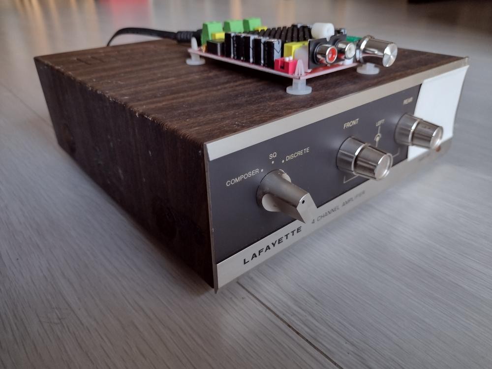
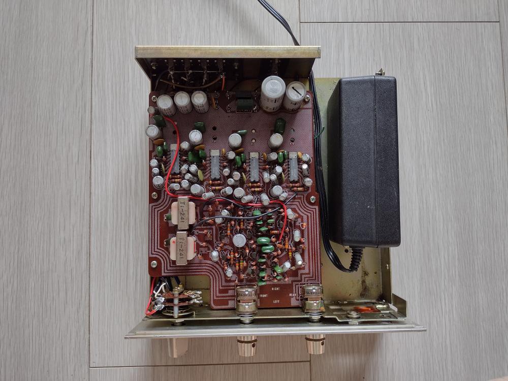
Knowing now that class D amplifiers are small, cheap and powerful, I thought I would buy another, more powerful, amplifier board and retrofit it to an old amplifier case. The amplifier you see came from some garage sale or other, I don't remember. I do remember that I bought it because it offered quadraphonic decoding. For a while in the late 70s, one could buy quadraphonic LP records that squeezed 4 channels onto the 2 channel groove of the vinyl. I had one or two such LPs and only ever heard them in stereo. But by the 2000s, multichannel digital recordings obsoleted the quadraphonic hacks. You can see the 4 power amplifier ICs in this top view of the amplifier.

I thought to put a SMPS inside the case and rewire the selector switch to choose between input sources. The amplifier board is totally disconnected and the volume pots do nothing. I only kept it because the volume pots are soldered on and removing them would leave even more holes in the front panel. (I may later take the pots off the PCB and remove the PCB, leaving the pots bolted on the case just for appearances' sake.)
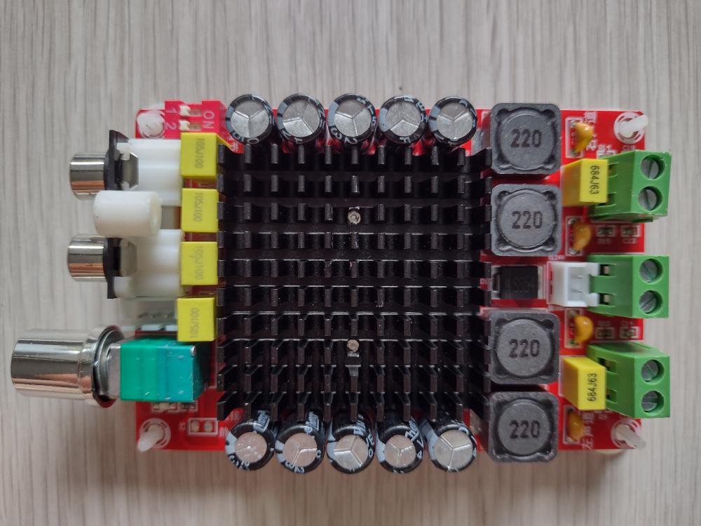
Here's the class D amplifier I bought for about $20 delivered. It takes up to 36V supply, and the SMPS which I think used to feed a laptop or something, can supply 32V. It's based on the TDA7498 chip.

So after a bit of of hacksawing and rewiring, I ended up with the fugly amplifier in the first photo. Fugly because the board is mounted on top of the case. To mount it inside I would have to think of some way to move the volume pot off the board.
Meanwhile I bought a modern AV receiver (not just a stereo amplifier, but multichannel, includes tuners, and even bluetooth input) on sale in the end of year offers so that does duty these days. I'll put this fugly hack to the back of my to do queue and get on with other projects.
-
Halving the execution time of an Arduino sketch
12/13/2023 at 08:04 • 0 commentsI have a large pile of 4164 and 41256 1-bit wide DRAM chips from the PC era. Many of them were extracted from sockets or boards. I was curious to know how many are faulty. A web search quickly turned up many designs for Arduino based DRAM testers. Most of them required only a few extra components in addition to an Uno or a Nano. Wiring is also simple so I wired up a tester on breadboard.
(There are complex versions that test a larger range of chips (e.g. additional voltage supplies), and have fancy features like an onboard display, but this was a one-off task. For the same reason I have no interest in any of the published PCB designs for Arduino shields.)
The first design I wired up was this:

This worked well. I didn't even wire up the LEDs because the serial console displays the status. Each chip takes about 80s to test. For succeeding chips I just have to press the reset button on the Nano as the program is already flashed into the MCU. It found a handful of faulty chips. Interesting that a batch of Mostek chips failed the test. Either their specs don't work with this tester, or a process fault ruined the chips over time.
But this circuit didn't handle 41256 chips. So I turned to this design:
The wiring is different. Here they have tried to minimise wire crossings from each side of the Arduino to the chip socket, at the expense of a less logical pin assignment. But it doesn't matter since a table handles the mapping in the sketch.

This also worked well. But with 4 times as many bits the testing time ballooned out to 288s. This meant many minutes waiting. There is only so much surfing I can do on the computer while waiting for tests to complete.
Hacking the sketch
I know that the Arduino library digitalWrite() and digitalRead() routines do a lot behind the scenes and this is reflected in the execution time. The Arduino documentation shows how to do direct I/O on the ports, but discourages it because for most sketches it doesn't matter and the sketch loses readability and portability. But the same page acknowledges there are situations where direct access is warranted. This testing sketch is just such a situation; it does a lot of bit I/O.
So I looked into how to rewrite the sketch to use direct I/O. A goal is to not change the structure of the code but use conditional defines to replace the digitalWrite() and digitalRead() routines.
For digitalRead() on the data out pin there is only one instance that needs to be replaced with inline code to read the pin, so that is easy.
Since writing HIGH or LOW are different code sequences in direct I/O, we define separate macros for the two situations, called dWH and dWL. When the optimisation is disabled, these map to digitalWrite(port, HIGH-or-LOW) and the program runs as before. When optimisation is enabled, these are defined as routines dWH() and dWL(). They use a switch statement to direct to the appropriate code for that pin. To discover the appropriate direct I/O statement one needs to consult the pin table of the Nano. The pins are also labelled in the sketch comments. So the overhead of direct I/O on a pin is a call, switch, and return.
Not all the digitalWrite() calls need to be substituted. Those dealing with the LEDs are not time critical and can be left as-is.
#define FAST_RW

#ifndef FAST_RW

#define dR_DO() digitalRead(DO)
#define dWH(p)  digitalWrite((p),HIGH)
#define dWL(p)  digitalWrite((p),LOW)

#else

#define dR_DO() (PINB & 1)

void dWH(int p) {
    switch (p) {
    case XA1:
        PORTD |= (1 << 2); break;
    case XA7:
        PORTD |= (1 << 3); break;
    case XA5:
        PORTD |= (1 << 4); break;
    case XA4:
        PORTD |= (1 << 5); break;
    case XA3:
        PORTD |= (1 << 6); break;
    case XA6:
        PORTD |= (1 << 7); break;
    case CAS:
        PORTB |= (1 << 1); break;
    case XA8:
        PORTC |= (1 << 0); break;
    case DI:
        PORTC |= (1 << 1); break;
    case WE:
        PORTC |= (1 << 2); break;
    case RAS:
        PORTC |= (1 << 3); break;
    case XA0:
        PORTC |= (1 << 4); break;
    case XA2:
        PORTC |= (1 << 5); break...
Read more -
Installing gcc for the 8088 on a RPM based Linux
04/08/2023 at 09:50 • 0 commentsThat's right, there has been a GNU C compiler (gcc-ia16) that generates code for the 16 bit x86 CPUs for quite a few years now, but it's due to the fork by TK Chia that much progress to a usable tool has been made in recent years. It's already in use by various projects, including the ELKS project.
Why would one use gcc-ia16 in preference to other existing free compilers such as Turbo-C (running under DOS, but you could run it in a VM) and Open Watcom, also enjoying a revival in interest? Well with gcc you get the prospect of compliance with a more up to date C standard, plus the possibility of someday compiling C++.
Why am I even tangling with this? I haven't had any 16-bit PCs for I forget how many years. Not even 32-bit only PCs, they are all 64-bit capable. I do have some 8088 chips and might get a round tuit making a SBC board for them. The real reason is I'm bored as I temporarily don't have access to my hardware toys. So I decided to see if I could install gcc-ia16 on my OpenSUSE Linux system.
Now that's definitely possible, because one can compile gcc-ia16 from source. But I'm lazy and decided to see if could adapt the Ubuntu packages, which are in DEB format. I remembered there is a utility called alien, which can convert between various package formats.
First of all alien is not in the official OpenSUSE repos, so I had to go to software.opensuse.org to find a contributed package. That went ok.
Next, I downloaded the DEB packages from the Ubuntu PPA for gcc-ia16. There are heaps of packages there, including versions for 3 Ubuntu releases. Cut to the chase, these are the ones that are needed: gcc-ia16-elf, binutils-ia16-elf, libi86-ia16-elf, and libnewlib-ia16-elf.
So I ran alien on one like this
sudo alien -v -k -r gcc-ia16-elf_6.3.0-20230219.07-ppa230219074~jammy_amd64.debAlien needs to be run as root or it will not be able to assign the correct ownership to the files in the resulting package. The -v shows progress messages, -k preserves the version number, and -r means the output should be a RPM package. Basically alien unpacks the DEB and reassembles it as a RPM. But it also checks the runtime dependencies, such as libraries. Despite being a complex tool, a command line driven compiler usually doesn't need much more than standard C libraries.
First problem, alien couldn't handle the Zstd compression of elements of the DEB. Zstd is a new-fangled compression scheme used in Ubuntu DEBs which replaces the old-fangled Gzip scheme.
I need a newer alien but when I tried to install that, it turns out my Perl isn't recent enough. Grr.
Ok, try another tack. Unpack the DEB, which is actually just a Linux ar archive, and convert the .zst files to .gz files and repack. That worked.
Oops, now it complains that the glibc version that I have on my system, 2.31, isn't recent enough for this application which wanted 2.32. Ok, instead of using the Jammy (Ubuntu 22.04) package, I'll drop back to the Focal (Ubuntu 20.04) package.
sudo alien -v -k -r gcc-ia16-elf_6.3.0-20230219.07-ppa230219074~focal_amd64.debAnd that converted ok.
One of the packages wanted libisl22 when I only had libisl15. This turned out to be the Integer Set Library originally from INRIA. Compilers have to manipulate sets at points during their operation. It turned out that the package comprises a dynamically loaded library and a symbolic link. And nothing required libisl15 so it would be quite safe to install libisl22 side by side and not worry about another application loading the wrong version.
After I converted all the packages just because I'm a bit obsessive, I changed the ownership of the resulting RPMs from root to myself, and made their mtimes the same as the corresponding DEB packages.
Now, would the RPM packages install correctly? I tried:
sudo zypper in gcc-ia16-elf-6.3.0_20230219.07-ppa230219074~focal.x86_64.rpmNotice I used zypper and not rpm, because zypper will detect any dependencies and satisfy them.
One other...
Read more -
A quick foray into the CH552 MCU
11/28/2022 at 02:20 • 0 comments
The CH552 is a very cheap (~$1) enhanced 8051 core MCU by Nanjing Qinheng Microelectronics, It's been on the market for a while and there are breakout board projects based on it, for example #CH552 Dragon , #CHUSBIE552 - CH552 Development board , #CH55xG Tiny on Hackaday alone. An Internet search will find many more. So this is old territory. Seeing cheap WeActStudio CH552 boards on AliExpress for less than $2 prompted me to get a couple to play with, despite being a bit adverse to the 8051 CPU architecture. (A decent C compiler can hide some of the ugliness.) This has the CH552 in a 20 pin package and an impressively small number of glue components. The board is only about the size of old 24 pin 0.6 inch width DIP chips. Even the 5V to 3.3V regulator is on the MCU chip. It's similar to other 20 pin MCU boards like the STM8 budget series.
The previous link is to a Github repo and you may wish to make a local clone to get access to the board details. The datasheets from the manufacturer, in both Chinese and English, are also provided.
One of the attractions of the CH55x series is on-chip support for USB which could come in useful for working with USB devices. In fact the USB connector is USB3, not the older USB2 micro USB connector. Today I just want to get it to blink.
For this I will be using Deqing Sun's CH55xduino, which is an Arduino environment for the CH55x devices. The best place to get it is from the official Arduino repositories, search for ch55x under Boards. This provides a familiar starting point for many people. SDCC, the compiler, isn't a C++ compiler, so the object oriented aspects of some Arduino libraries have to be rewritten in plain C, and user code adapted to suit. CH55xduino has made commendable progress on this front. Later on, I'll probably invoke SDCC directly from Makefiles.
For Linux, CH55sduino suggests installing a udev rule so that you can download code as a normal user. I modified it a bit, the original made the USB port RW to all. Instead I chowned it to the dialout group, which is the suggested group for accounts that need to communicate with serial devices on my Linux distro.
# CH55x bootloader
# copy to /etc/udev/rules.d/
SUBSYSTEM=="usb", ATTRS{idVendor}=="4348", ATTRS{idProduct}=="55e0",GROUP="dialout"
To get the blink sketch, I went to Examples and chose the CH55x version. One thing has to be edited, the definition for LED_BUILTIN has to be changed to 30, because the WeActStudio board has the LED on this line, by looking at the schematic from their git repo.
So all I had to do was select Upload, and after a while the blue LED duly blinked.
Now that I know it works, it'll go into my collection of MCU breakout boards which I will put to use when I get a round tuit. There seems to be a worldwide shortage of round tuits, but we all have to cope in our own way.
-
A short experiment with a DTL ring oscillator
11/20/2022 at 10:28 • 1 comment
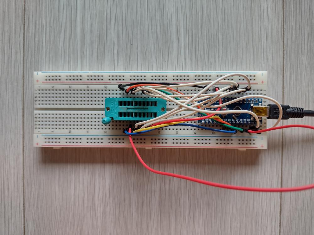
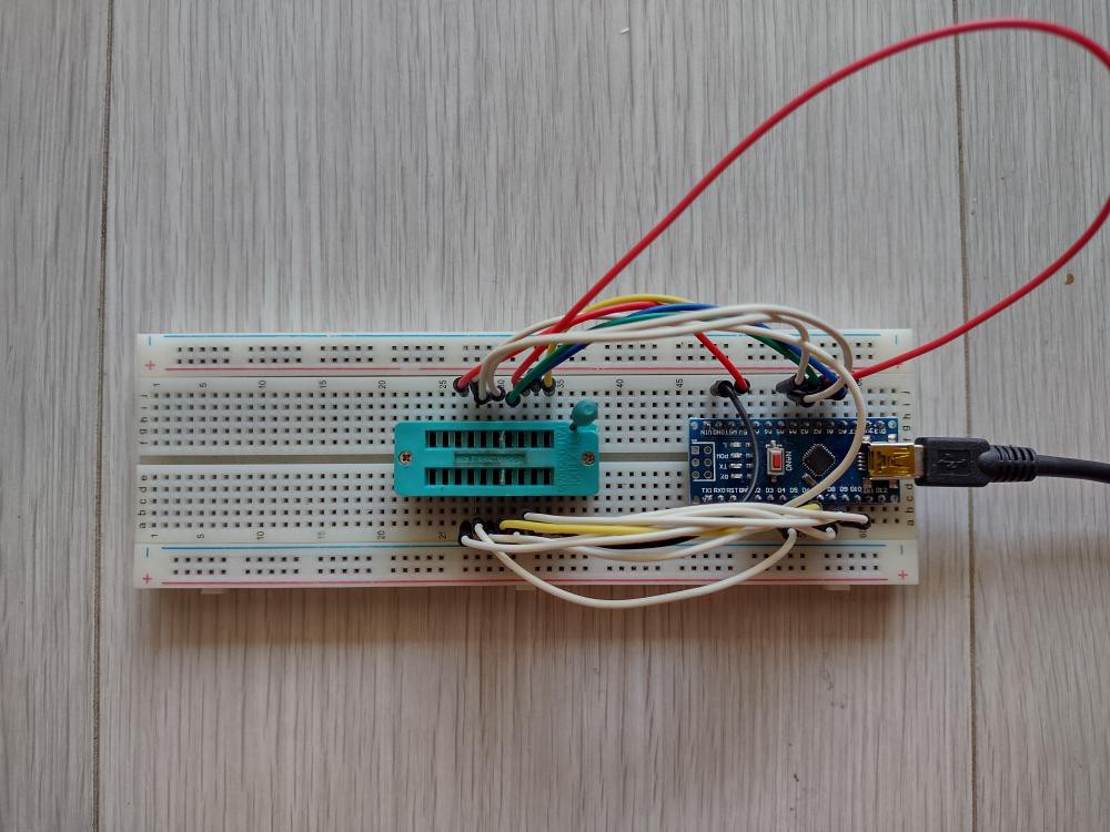
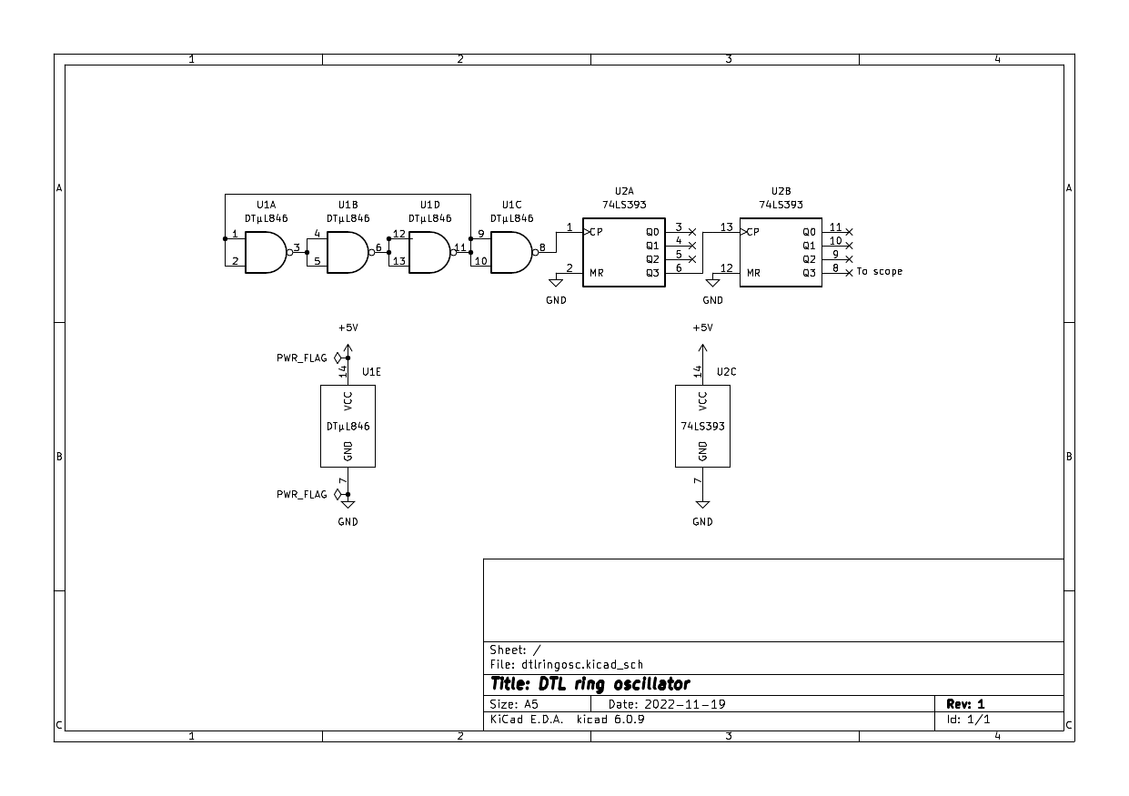
Following #Ring Oscillators: Fairchild DTL 949 I decided to see if I could make some use of a handful of DTµL 846 quad 2-input NAND chips I have, since it's very easy to wire up a ring oscillator. 3 gates form the oscillator and the fourth buffers the output. I do not have a scope of sufficient bandwidth to measure to 10 MHz so I sent the output to a 74LS393 as a divide by 256 counter. So to get the original frequency, multiply by 256.
The DTL chip was mounted on a repurposed precision IC socket, slightly damaged by a soldering iron. This avoids any stray capacitance from breadboards, but allows different chips to be plugged in. Here are the results of the few good chips I have (the others in my pile had one faulty gate):
- 37 kHz -> 9.5 MHz
- 36 kHz -> 9.2 MHz
- 38 kHz -> 9.7 MHz
The frequency stability is not great, it fluctuates in the short term. In the medium term I noticed it sped up a bit after "warming up". But it's pretty certain that it will not exceed 10 MHz.
So what to do with these oscillators? Where can I use them that doesn't require the accuracy and stability of crystals, which I'm not short of? Perhaps where I don't want the added components for a crystal oscillator. But even ancient MCUs have built-in gates for crystals, requiring only a couple of load capacitors. Modern MCUs even have a builtin RC oscillator mode which is good enough when timing isn't critical. Maybe some kind of coarse timing circuit? But the divisor would be large, so might as well use a MCU again. I'll put that question in the back of my head while I move on to other projects.
Out of interest I tried a 74LS00 chip (which has the same pinout) in the harness and I got 133 kHz -> 34 MHz.
-
The Soul of an Ancient Calculator
08/30/2022 at 06:45 • 0 comments
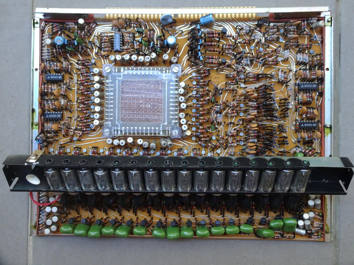
Around 1990 I picked up an old Sharp calculator from a flea market because it was only a couple of bucks and had 16 nixies. I believe it was this Sharp calculator model from 1969. I say I believe because at some point when I moved I threw away the case and keyboard, no perceived utility. But that the CS-361 had magnetic core memory fits with the main board I still have.
Well it's a pity I don't have the complete machine because it could have been of interest to a museum. I'm fascinated that it used core memory. I thought it was for microcode storage, but the web page says it was for registers. The microcode probably consists of diode logic. You can also see it has germanium transistors in metal cans and plastic silicon transistors.
No, I'm not going to try to reverse engineer the logic. Just thought I'd publish a picture of the main circuit board before I put the nixies to other uses.
-
A firmware monostable (and other circuit blocks)
05/05/2022 at 08:39 • 2 commentsRecently I was looking to use a 74LS123 dual retriggerable monostable as pulse stretchers. I have used them before in a DTL clock. I only needed a subset of the pins, the /A input for the input pulse and the /Q output for the output pulse. Two additional components, a resistor and a capacitor are needed for each pulse stretcher. Here is the datasheet page with the truth table, only the last 3 rows of the 123 truth table are of interest.

Then it occurred to me that I could use a MCU to do the same job without the R and C. Here's an Arduino simulation:
//
// Emulate half of a 74LS123 in firmware
//

#define NA 2
#define B 3
#define Q 4
#define NQ 5
#define DELAY 1000    // milliseconds

void clear() {
  digitalWrite(Q, LOW);
  digitalWrite(NQ, HIGH);
  digitalWrite(LED_BUILTIN, LOW);
}

void set() {
  digitalWrite(Q, HIGH);
  digitalWrite(NQ, LOW);
  digitalWrite(LED_BUILTIN, HIGH);
}

void setup() {
  // put your setup code here, to run once:
  Serial.begin(115200);
  pinMode(NA, INPUT_PULLUP);
  pinMode(B, INPUT_PULLUP);
  pinMode(Q, OUTPUT);
  pinMode(NQ, OUTPUT);
  pinMode(LED_BUILTIN, OUTPUT);
  clear();
}

void loop() {
  // put your main code here, to run repeatedly:
  byte a, b, trigger;
  do {
    a = digitalRead(NA);
    b = digitalRead(B);
    trigger = (!a == b);
  } while (!trigger);
  //  Serial.println("Triggered");
  set();
  unsigned long later = millis() + DELAY;
  while (millis() < later) {
    a = digitalRead(NA);
    b = digitalRead(B);
    trigger = (!a == b);
    if (trigger) {
      //      Serial.println("Retriggered");
      later = millis() + DELAY;
    }
  }
  //  Serial.println("Off");
  clear();
}
Great, I hear you say, you've just written a firmware equivalent for a circuit, so what?
But what if the MCU is an ultra-cheap one like the 3¢ ones discussed over 3 years ago? That's so cheap that you could admit the audacity of thousands of transistors on a chip substituting for maybe 50 transistors on the monostable chip. You could (re)program the MCU for the duration you want. You might not be able to get very short pulses of the order of microseconds, but on the other hand you could have extremely long durations, days even. And it would be far more accurate than an RC network.
Now such MCUs are certainly cheap enough to be 7-segment decoders and the like, but for 3¢ we can contemplate substituting for even simpler circuit blocks such as switch debouncers. Normally you would fold such functionality into the main MCU's firmware, if the product has one. But you could simplify the firmware by splitting out the fuctionality into another chip.
One thing to note is that in practice you want to read in all the inputs in one instruction, so that you don't get race conditions between /A and B changing. This can be done by reading in a port in one go. You can also ensure that all outputs change at the same time by making sure that the Q and /Q lines are on the same port, although output skew is less of an issue for most applications.
In my application I only need /A and /Q so only two I/O lines are needed. So an 8-pin MCU with 6 I/O lines could support 3 such firmware monostables.
-
Bizarre HaD buglet
04/16/2022 at 08:11 • 0 comments
Notice that the details instead of saying "wrote 2 days ago" is in the Chinese translation. This doesn't happen all the time, only sporadicaly, and to other people's pages too. Nothing else is turned into Chinese, only dates. Next time it happens I'll inspect the HTML element to see if it arrived that way from HaD.
-
Is it possible to drive Titan Micro display controllers with an I2C bus?
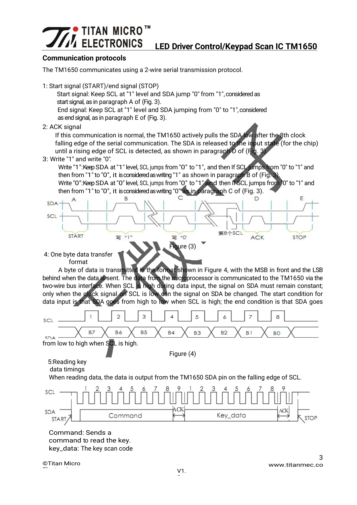
04/14/2022 at 18:00 • 0 commentsMany people have noticed that resemblance to I2C protocol of the protocol used by the Titan Micro series of LED display controller chips, of which the TM1637 is most often seen, on display modules that cost only a dollar or less, not much more than the parts that go into it. These modules are useful for simplifying projects and reducing the number of drive lines needed of the MCU. I myself have written a comparison of the two protocols, I2C and let's call the other TMP.
I saw a suggestion on EEVBlog that TM chips could be driven by a standard I2C bus. Was this a tested idea or speculation, I wondered. I decided to test the idea.
While the low level details of the start and stop conditions are the same, two other aspects need to be handled:
- The bit order in the stream is most significant bit first for I2C and least significant bit first for TMP. This requires that all commands and data to the chip be byte-reversed before use. This isn't as onerous as it sounds. Constants for commands can be reversed in program code. For the display data which is generated from a font table, the table entries can be reversed at coding time. Or one could regard the segment to bit mappings to be reversed. In the program below I have elected to do it with a function to keep things simple.
- TMP doesn't have a slave address, the first byte after the start is a command. So the command would go where the I2C slave address would go. The complication is that in I2C the LSb of the address is the direction bit, 0 for master to slave and 1 for slave to master. We are interested in the former. That means that the LSb has to be 0. Taking into account the byte reversal, this means that only TMP commands below 0x80 can be sent. The silicon is entitled to look at the direction bit and not transmit to the slave if it's not 0.
The previous explains why the following Arduino sketch for scrolling digits doesn't work as expected. The LED display doesn't turn on, and only running a working bit-banging sketch before running this one will the LEDs light up.
The set address command of TMP also doesn't work as it's 0xCn where n is 0..5. At power up n defaults to 0, so all 6 bytes of the data have to be sent otherwise not all the digits can be seen.
// Uno
#define SDA     A4
#define SCL     A5

#include <Wire.h>

static uint8_t startnum = 1;
static uint8_t display[6];

static const uint8_t font[] = { 0x3f, 0x06, 0x5b, 0x4f, 0x66, 0x6d, 0x7d, 0x07, 0x7f, 0x6f };

static const uint8_t revmap[] = { 0x0, 0x8, 0x4, 0xc, 0x2, 0xa, 0x6, 0xe, 0x1, 0x9, 0x5, 0xd, 0x3, 0xb, 0x7, 0xf };

uint8_t byterev(uint8_t b)
{
  uint8_t lo = b & 0xf;
  uint8_t hi = b >> 4;
  return revmap[lo] << 4 | revmap[hi];
}

void setdisplay()
{
  Wire.beginTransmission(byterev(0x8f >> 1));  // set brightness (doesn't work)
  Wire.endTransmission();
}

void writedigits()
{
  Wire.beginTransmission(byterev(0x40 >> 1));   // data command (works)
  Wire.endTransmission();
  Wire.beginTransmission(byterev(0xc0 >> 1));   // set address (doesn't work)
  Wire.write(display, sizeof(display));
  Wire.endTransmission();
}

void setup()
{
  pinMode(LED_BUILTIN, OUTPUT);
  pinMode(SDA, OUTPUT);
  pinMode(SCL, OUTPUT);
  Wire.begin();
  Wire.setClock(100000);
  setdisplay();
}

void loop()
{
  uint8_t first = startnum;
  for (uint8_t i = 0; i < sizeof(display); i++) {
    display[i] = byterev(font[first]);
    first++;
    if (first >= 10)
      first = 0;
  }
  writedigits();
  delay(500);
  startnum++;
  if (startnum >= 10)
    startnum = 0;
  digitalWrite(LED_BUILTIN, (startnum & 0x1) ? HIGH : LOW);  // flash at 0.5 Hz to debug
}
The video at the top shows the scrolling one should expect to see, albeit on a ESP8266 platform instead of Arduino.
But the send data command does work as it's 0x40. So one solution would be to use bit-banging to initialise the chip, then switch to using the silicon support for I2C for display updates. It would mean slightly more code, but not much for the display update. Here's a slightly modified version of the previous sketch...
Read more -
Costing assembly service for my PCB
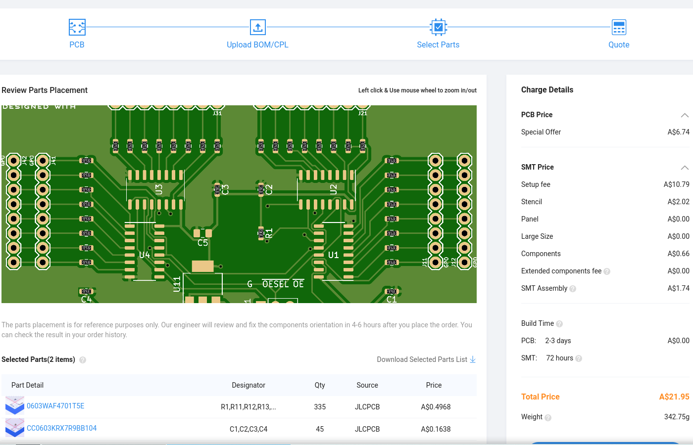
03/07/2022 at 07:49 • 8 comments
Today I decided to dip my toes into getting a PCB design of mine assembled to avoid a lot of hand soldering. JLCPCB gives out monthly coupons to offset the setup charge so that reduces the total price.
Here's what I found out, in no particular order:
It's quite straightforward to generate the two files required: the Bill Of Materials (BOM) and the Component Placement List (CPL) files, also called POS files, from KiCad. Both are CSV format files. There are many ways to do that. Here's what I did.
The BOM can be generated by the XSLT converter recommended by JLCPCB. This has to be first installed in your scripts directory then registered as a generator for eeschema. But you should also add an extra field to each symbol called LCSC. This is where you put the part number, more further down.
The CPL files (top and bottom) are generated from pcbnew (yes, BOM from eeschema and CPLs from pcbnew, reason is because not all symbol fields are passed on from eeschema, maybe in some future version). After that the header line needs to be changed to JLCPCB's headers, This sed script will do it:
#!/bin/sh
exec sed -i '1s/Ref,Val,Package,PosX,PosY,Rot,Side/Designator,Val,Package,Mid X,
Mid Y,Rotation,Layer/' "$@"
But before you generate the BOM, you need to add the LCSC (a JLCPCB sister company) part numbers. Go to the parts search and find the part numbers you need. For example C23162 is a 0603 profile 4.7k resistor.
JLCPCB has basic parts and extended parts. Basic parts are already in the PCB factory, extended parts have to be ordered from LCSC so an extra fee is levied. Vanilla parts like resistors and capacitors are definitely basic parts. Probably jelly bean transistors, diodes, and common ICs too but see next point.
There is a minimum charge of quantity 20 for each part with headroom of 5 for wastage. They won't credit you for any leftovers. Hence the recommendation to reduce the number of different parts. For example if your circuit has lots of 4.7k resistors already and a particular resistor calls for 3.9k, can you change that to 4.7k?
You upload the Gerber files as usual for PCB fabrication. At the bottom you then select SMT assembly. NB: If you only order 5, you can have 2 assembled and you have to do the rest yourself. So you have to order a minimum of 10 boards if you wish to avoid doing 3 by hand. Only one side of the PCB will be assembled. So put all the SMT components you don't want to do yourself on one side, usually the top. Thus only one CPL file is needed.
You then upload the BOM and the CPL files and a quote will be generated, a sample is in the screenshot. But before you do that you may wish to cull the components in the BOM and CPL files that are not to be assembled. But the web page will filter out those components without a part number anyway.
You can see that the setup fee and stencil cost the most. The components and SMT assembly are really cheap, even for the hundreds that I used in my sample order.
The preview window also shows if your CPL file is correct. The black chips are the components which will be placed by machine and soldered. At some point in your adventures you may encounter this issue:

The transistors are rotated 180° from the correct orientation, and although the IC can barely be seen (due to stock shortage at the time I did this quote), it's 90° wrong too. It all comes down to a mismatch between what is regarded as the normal orientation between KiCad and their database. To fix this you have to edit the orientation column in the CPL file and try again.
Unfortunately you have restart from the Gerber file upload.(May not be necessary.) If you haven't corrected the orientations before the job is started, their engineers will fix the issues and send you a preview for confirmation, so it is strongly encouraged that you provide a mark, such as the filled circle you see near pin 1 of U1 to help them get it right.The coupon is $8 so that brings the cost down to $14....
Read more -
I should pay more attention when assembling
12/24/2021 at 09:33 • 0 comments
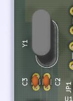
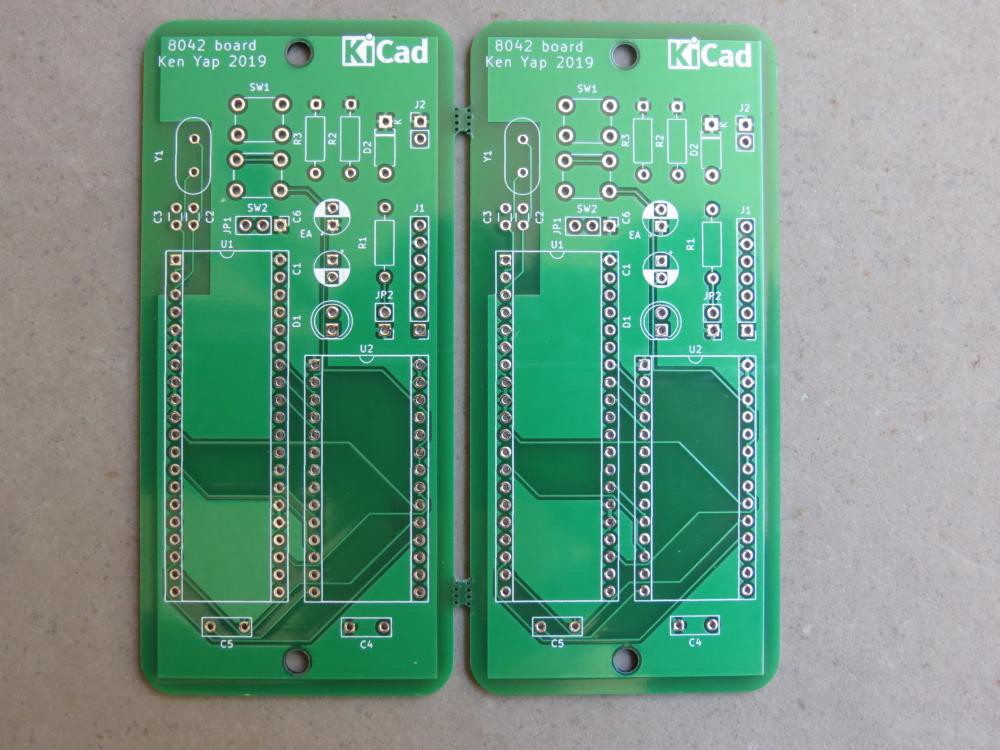
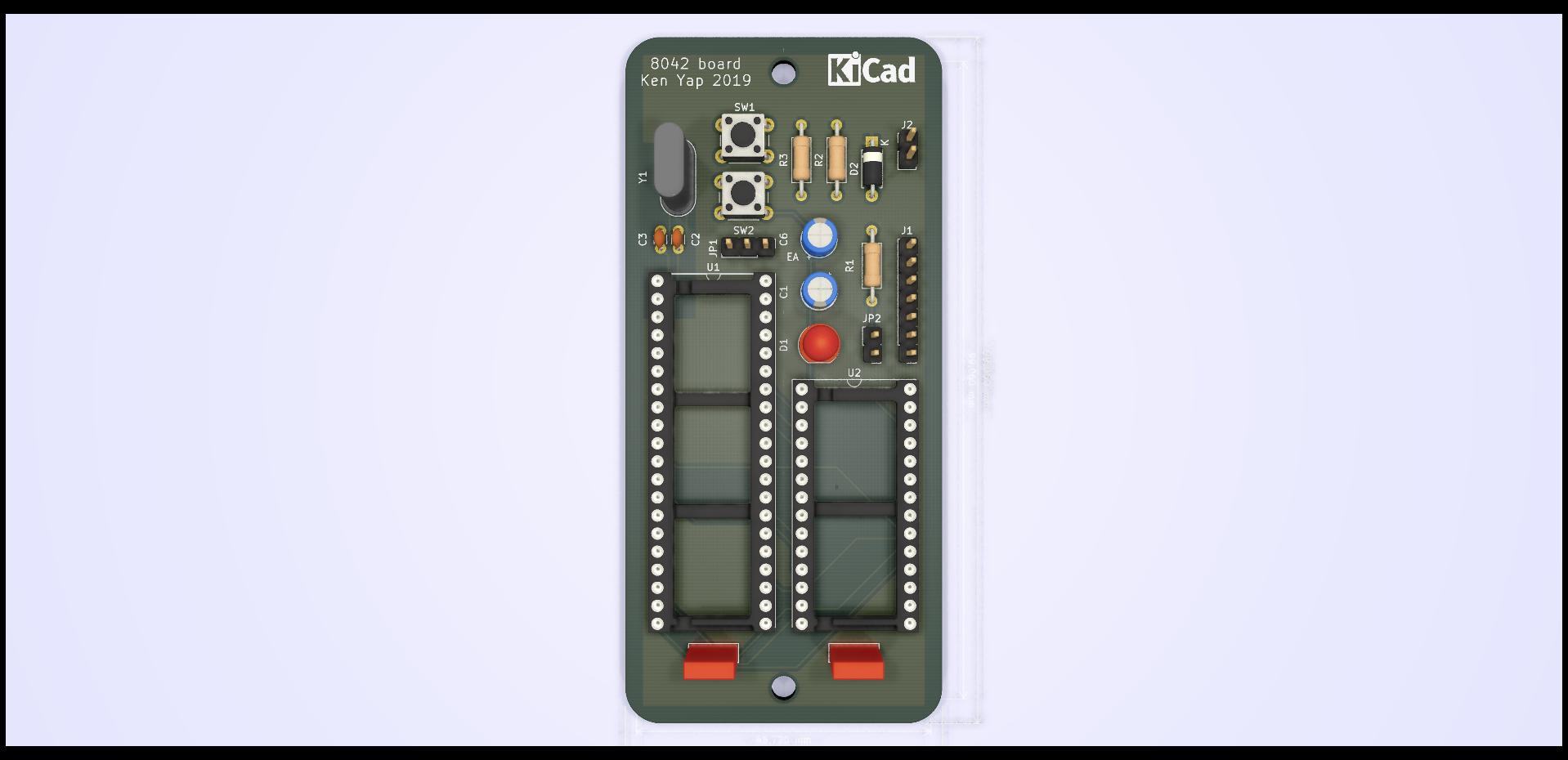
I was putting together a few more 8042 boards since the original order netted me 5 PCBs and they were panelised 2 per PCB. One didn't work with the same EPROM as the others. Today I compared it with a working board and noticed that the crystal capacitors were supposed to be like the 3D rendering above, but I had soldered them in rotated 90°. In fact the silkscreen has lines indicating the orientation, and the labels are also a hint. That was dumb of me. A few minutes later it was fixed and worked straight off.
Solved a puzzle, a nice holiday season present for myself! Happy holidays everyone and stay safe!
-
Adventures getting an ESP8266-01 relay module running
12/07/2021 at 12:22 • 0 comments
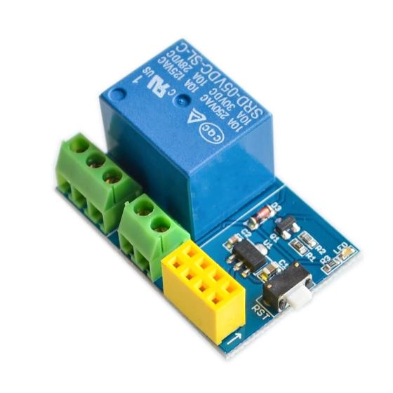
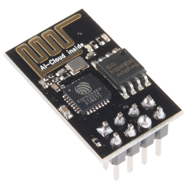
I bought a relay module and the matching ESP8266-01 WiFi module for a couple of bucks (bargain!), in order to experiment with remote control. In particular I'm thinking of fitting one into an amplifier for remote turn-on. The module is quite small, that photo is larger than life size. It's about the size of a matchbox and perhaps twice as high. The ESP8266-01 fits onto the 8 pin yellow socket in the picture. These are my notes on getting it to work. I will augment this page as I encounter and solve issues.

Sparkfun Electronics, ESP-01, CC BY 2.0
A search for ESP8266-01 will get you quite a few instruction pages. Usually they suggest you start by connecting a serial terminal on an Arduino to it. You could also use a FDTI adaptor. I came across these issues:
Diagrams show that you have to take the EN pin high (3.3V) to allow it to work. But the RST pin must also be taken high or the module may not respond. Later on you should make provision to ground GPIO-0 to flash programs if that's what you want to do.
Beware of "smart left and right quotes" on web pages if you copy and paste commands, in particular the command to register with an AP, giving the SSID and password. You must use the ASCII double quote.
In one Fritzing diagram, hosted by the Arduino site no less, a 5V to 3.3V regulator is shown on the breadboard you'll need to expand some connections like 3V3 and GND. I'm not sure why; the Arduino board, at least the Uno, already has a 5V to 3.3V regulator.
I came across one article discussing ways to expand GPIO. One way is to use an I2C extender. Besides GPIO-0 and 1, Rx and Tx could be used for a total of 4. But such measures are probably unnecessary nowadays; buy a later ESP8266 or ESP32 module with far more I/O pins for not much more money.
Last edited 2021-12-08
-
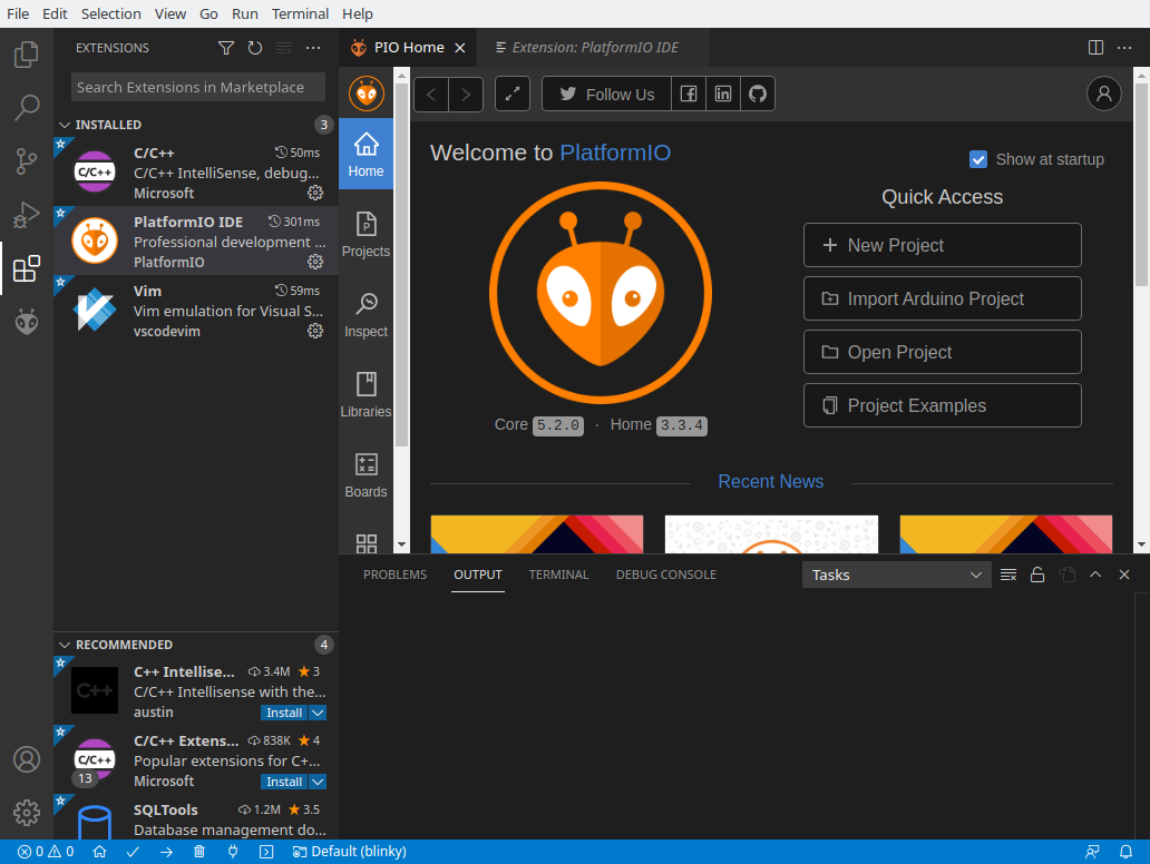
Adventures debugging STM8 with PlatformIO
10/13/2021 at 10:02 • 0 comments
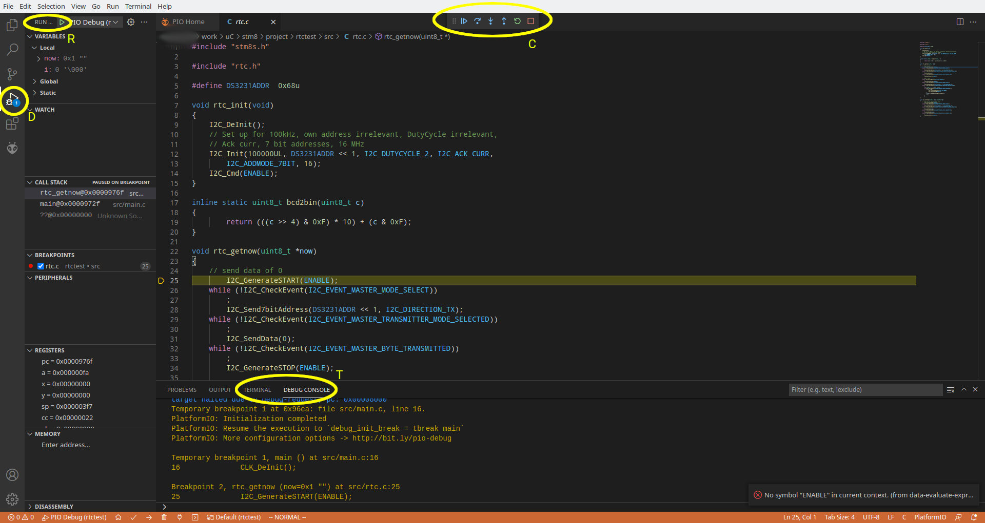
I previously showed how to set up PlatformIO. Now I demonstrate putting PlatformIO to debugging firmware for the STM8. Debugging is where the IDE comes on its own as you can see multiple pieces of information on the screen, unlike a text debug session.
Assuming you have all the build and debug tools installed for STM8 in PlatformIO, and you have the board connected to your host computer with a STlink dongle, then when you open the file explorer to the code you want to debug, and click on icon D, you should get a display like this. As you can see the relevant controls aren't exactly grouped well, they are scattered all over the screen, but you will get used to that. The left column shows the state of the program, including any breakpoints.
To set a breakpoint, right click on the space before the line number and it will allow you set or delete breakpoints. As you can see there's one on line 25.
Start the program with the arrow at R. It will first stop at the beginning of main(), then you can continue using the continue arrow control at C. Here you see we have paused at line 25. You can step into lines or over lines using the controls. These correspond to the gdb commands S and N and can be entered as text at the prompt under the debug console T. However if the program has gone into a loop without hitting any breakpoints, you will have to use the interrupt button at C. This cannot be done from the prompt. You can also restart the session.
Other gdb commands like print [variable] also work, but it's more convenient to watch the variable display in the left column.
One drawback to using debugging from the IDE is that the generated firmware will be larger and may not fit in flash memory if you are near the limits.
-
Addresses need to be doubled in SPL for STM8
10/10/2021 at 22:47 • 0 comments
While interfacing a DS3231 RTC to a STM8 development board using the Standard Peripherals Library and PlatformIO (BTW, you don't need to build SPL, it's provided by a PlatformIO package), I fell into a simple trap. I assumed that the address wanted by the I2C functions of the SPL was the one stated by the manufacturer. In the wire protocol this is the top 7 bits of the address byte (0x68 in the case of the DS3221) and the bottom bit indicates the direction of data transfer. However the SPL functions want the address shifted one bit left (or doubled if you prefer). This is obvious when looking at this SPL function.
void I2C_Send7bitAddress(uint8_t Address, I2C_Direction_TypeDef Direction)
{
  /* Check function parameters */
  assert_param(IS_I2C_ADDRESS_OK(Address));
  assert_param(IS_I2C_DIRECTION_OK(Direction));

  /* Clear bit0 (direction) just in case */
  Address &= (uint8_t)0xFE;

  /* Send the Address + Direction */
  I2C->DR = (uint8_t)(Address | (uint8_t)Direction);
}
I assume the SPL writer did this to avoid a runtime left shift of the address parameter, and wanted the SPL user to do this themselves, as the address is usually a constant in the code and the doubling folded by optimisation. Programmers who use the I2C registers directly without SPL will normally take care of this point when setting the address.
Code examples of using I2C with STM8 SPL are a bit thin on the ground, but this is one that helped me.
The embarrassing other problem that prevented my RTC reading routine from working was hardware. I had an unsoldered joint on the B5 (SDA) pin. Now I can see in the PlatformIO debug session (which uses openocd and stm8-gdb) that the correct time and date bytes are returned to the caller.
-
Fooled by idiosyncratic resistor network
09/29/2021 at 12:34 • 0 comments
One of my projects uses a 4 unit resistor network for switch pullups. I picked one out of my pile of spare parts, some stripped from old boards. However the buttons behaved strangely, one worked, but another caused strange symptoms. I checked the circuit board for breaks in the trace to the faulty button, but seeing as it did something, that couldn't be the reason.
Finally it occurred to me to measure the resistor network. It turned out that contrary to nearly all resistor networks sold today where the common junction is at one end and indicated with a dot, or band, this one had the common junction in the middle. There was a filled circle in the middle of the text, thus: 10 ● kΩ. I thought it was just strange punctuation, but the circle was the position of the common pin. Once I replaced it with a regular unit, the circuit worked as I wanted. Lesson to me: check components when populating the board or face rework.
I couldn't even find a picture of such a resistor network; it must be rare. I know that manufacturers sometimes used resistor networks with unusual topology for boards, like A-D converters.
-
Adventures with the Sipeed Longan Nano development board
09/24/2021 at 11:59 • 0 comments
The Sipeed Longan Nano development board by Seeed Studio is based on the Gigadevice GD32V which implements the RISC-V architecture. It has an impressive list of features, which you can read for yourself. Low power consumption is claimed as one, a third of the Cortex-M3. Actually if you go to that Seeed Studio link you will find that a newer v1.1 is about to be released. The older v1.0 is listed as out of stock. However it is still sold by many vendors on AliExpress. I bought one for about $12 delivered with a tiny LCD screen on top. I figured I can experiment with the v1.0 now and display stuff on the LCD and buy v1.1 when it is released. Never can have too many toys. 😉
Several things can be noted from the photo. The USB connector is USB-C. So if you have been using micro-USB cables, it's time to upgrade. Fortunately I had a spare cable. There are two buttons. One is RESET and the other is BOOT. What's the difference? RESET is what you expect. BOOT is to be held down before RESET when you want to flash firmware (your program binaries) onto the board. We met the same scheme this in #Adventures with ESP8266-12E, NodeMCU, and Lua One more thing cannot be seen in the photo. On mine, there are 4 pins for attaching a serial interface. If you don't have a FDTI type converter from USB to serial, then you'll have to get one.
I do have a USB to serial converter but I was loath to use a USB port of my computer to power the board, and use another USB port to connect to the serial interface. But it turns out that the USB port on the board can indeed be used to download firmware using the DFU protocol. The Linux utility for this is dfu-util. But it turns out that I may eventually need to use a second connection as DFU doesn't support debugging.
For development, PlatformIO (see my page on PlatformIO setup) is the required IDE, and this board is supported. That page is a bit out of date as upload_protocol = dfu is not mentioned as the setting you need to add to your platformio.ini of your projects. The other thing you should do is add a udev rule so that your Linux account can access the USB port. Before you flash the firmware you should hold down BOOT, then pulse RESET so that the USB device materialises. You can check if the device exists with dmesg -T -w as root, or with dfu-util -l which gives a lot more info. This needs to be done for each download as the USB device disconnects after completion. I think I may need to get a couple of small styluses to avoid squeezing my huge fingers on the tiny board. Here is a gist which mentions many key steps.
I copied one of the three example projects available for this board, all versions of blink. I chose nano-blink and succeeded building the firmware with only a few compiler warnings. However when it tried to flash the firmware, dfu-util reported an Error 74 which is a known issue. I found the more recent version in my Linux distro's repositories. However I could not delete the PlatformIO installed dfu-util package as it insisted on installing it as a platform dependency. So I subverted it by renaming the old binary and making a symlink to /usr/bin/dfu-util. After that blink worked. Wow, exciting. Not!
Well that should get you started. I'll have to see what more exciting programs I can run on it, in particular ones that use the display. Incidentally in my rabbit hole explorations I found that there is a toolchain for Rust, so you could program in this safer language that retains the efficiency of C/C++.
-
Adventures setting up PlatformIO on Linux
09/16/2021 at 01:28 • 0 comments
I've started exploring PlatformIO and thought I'd set down my experiences so that others can get some quick answers to questions that they may have which may help navigate the copious documentation they will encounter on the Internet. First some important links:
PlatformIO: Open source professional collaborative platform for embedded development
PlatformIO project page on Hackaday, lots of links
Visual Studio Code: Coding IDE that provides an IDE for PlatformIO via an extension
What is it?
In short an IDE for enbedded development that is cross-platform and caters for multiple processors. It can fill the space that Arduino occupies and exceed it.
How to get it
First install Visual Studio Code (Vscode from now on) for your platform. Vscode is separate from PlatformIO but the latter leverages the former by an extension. On my Linux distro it was as easy as adding the Vscode repository to the software manager and then installing it as a package. You will get monthly updates. You can use it also as a code editor for your non-embedded projects BTW. It has tons of extensions, so many in fact that it can be hard to select, for various languages and environments.
Next fire up Vscode, find and install the PlatformIO extension. Starting a project in this will bring in the PlatformIO core. Installation is done in your own directories so no system privileges are required.
I actually took another path, I installed PlatformIO core from the command line using these instructions. It was probably unnecessary but it gave me insight to what was happening behind the scenes. Core is the CLI part of PlatformIO, and is written in Python, which allows it be easily cross-platform.
Depending on the parameters of the project you have created, other packages will be brought in. For instance I selected a STM8 platform on the blue breakout board, using the ST Standard Peripherals Library (SPL). This then pulled in various development packages based around SDCC, as well as support utilities like downloaders and debuggers. Note that this is separate to any other SDCC you may have installed on your computer, and will be stored in your private PlatformIO directories (~/.platformio on Linux).
How to run it
Fire up Vscode and look for PlatformIO in your installed extensions. Go to its home and start a project. You will see that it will create a project directory with a standard structure made popular by Ruby On Rails, Rust, Gradle, and other frameworks with subdirectories for source, includes, libraries, and build target directories which hold the generated objects.
You can also try to install an example project, blink for example. You will get a project directory in the standard structure populated from the PlatformIO repositories.
Wander around those directories and read the README files left there.
How to build projects
You can use the IDE for all actions, but I found it instructive to cd into the project and run commands using the PlatformIO CLI commands at the beginning. (You may need to add those commands to your shell's repertory by editing PATH or by making symlinks.) The main one is platformio, or the shorter pio. You can do things like:
pio run
pio run --target clean
and others you can discover by pio -h.
You can actually do quite a bit of work from the CLI but for advanced operations like debugging, the IDE is the way to go.
You'll notice a file at the top directory of the project: platformio.ini This describes the build options. For example mine contained:
[env:stm8sblue]
platform = ststm8
board = stm8sblue
framework = spl
You can have multiple stanzas, you will end up with multiple products in .pio/build as a result. Many standard combinations are already in PlatformIO so you shouldn't have to create a new configuration if your platform is well established or PlatformIO is already supported by its manufacturer.
Where are the projects stored?
By default the projects directory is ~/Documents/PlatformIO/Projects...
Read more -
Worn out EPROMs
09/14/2021 at 01:39 • 0 comments
© Raimond Spekking / CC BY-SA 4.0 (via Wikimedia Commons), Mitsubishi M5L2764K-5377 , CC BY-SA 4.0
(Not a picture of brand that suffered the problem, but could happen to any brand.)
Today I was working with some ancient 2764 8kB EPROMs. The symptom I was seeing was that the firmware only partially worked in the circuit. A bit later on, even fewer functions worked. Right away I suspected the EPROM of bit rot. Another EPROM of a different brand worked fine. There are various explanations for this but it all comes down to age and sensitivity of the on-chip amplifiers dropping. May also have to do with the programming algorithm. It might work better if I zap it more than once next time I program that chip. And to wait a while before verifying the EPROM against the file.
I might try to write a self-checksumming routine for firmware. Software like SRecord can automatically generate a checksum to be inserted in spare bytes. Question is what to do when the self-check fails. Blink a LED perhaps.
Addendum: Testing shows that appears to be more likely to happen with EPROMs that require 21V programming. I've read a post on EEVblog that the the programmer I have, the TL866A, isn't really capable of attaining that voltage even though it's advertised so. Newer TL866 models removed the 21V option. So the EPROM may be incompletely programmed and may "fade" with time. Fortunately I have 12.5V programming voltage EPROMs that I can use, and can retire the older chips.
-
A random walk through 300 40+ year-old circuits
07/11/2021 at 09:22 • 0 commentsI picked up the book 300 Circuits by Elektor Publishers from my shelf today. The title page showed that I had acquired it 22 Nov 1982 and it was the second edition. As the first edition was published in 1979, this makes the circuits more than 40 years old. I think the designs give good insight into how much electronics has advanced over the decades. So I've decided to pick 10 circuits from it at random to comment on. The last one is a favourite of mine.
Most of the time I won't show the circuits, I will just describe them. Very little is lost this way.
First let's generate 9 random numbers between 1 and 300 inclusive. The 10th is selected by me.
$ for i in {1..9}; do echo -n "$((RANDOM%300+1)) "; done; echo
199 146 73 220 233 259 4 50 83
Sharp readers will note that because $RANDOM ranges from 0 to 32767, the first 68 circuits have a larger chance of being selected, but not by much. So let's go to the selection.
199 Cascode current source
This circuit uses a transistor whose base is fed from a voltage reference of two Si diodes in series. The constant current is then 0.6/R where R is the emitter resistor. An improved version uses a second transistor in series with the first one's collector to improve the constancy w.r.t. supply voltage. I'll show the second circuit to make things clear.

This is still a useful technique although more likely to appear as part of a larger design. Or you can get a constant current IC off the shelf.
146 Division by 7
This showed how to get a TTL 7490 (anybody remember this?) to divide by 7. The trick is because 7 contains three 1's and the reset to 0 gate has only 2 inputs, you don't reset to 0, but reset to 9 on 6. Thus the sequence is 0 1 2 3 4 5 9 0 ...
73 Dark room aid
This meter circuit used a LDR to measure the brightness of the image projected by the enlarger to indicate the exposure needed. Does anybody still remember dark rooms, enlargers, photo paper, chemicals, the lot? I used to have a commercially sold meter embodying this idea. You swung a diffusing filter over the enlarger lens to average the image brightness and then by turning meter's dial until a neon lamp (no cheap LEDs then) lit, you could read off the seconds of exposure needed. I'm also certain it had to be calibrated for each batch of photo paper.
220 Blown fuse indicator
This is quite a simple idea. A neon lamp, with rectifier diode, smoothing capacitor and limiting resistor, are put across a fuse. When the fuse goes open circuit, the voltage across it is sufficient to make the lamp light.
These days unlicensed people aren't allowed to mess with mains wiring, so one can't actually put this idea into the field.
233 Triangle generator
This uses an op-amp to generate a triangular waveform. The sort of thing you learn in a course on using op-amps.
259 Triac control
This is a standard diac/triac circuit for controlling a load connected to the mains, such as a lamp. They worked with incandescent lamps, not with (compact) fluorescent lamps, and I don't know about LED lighting. In any case the rage these days is to control the LED lighting, including colour, through a network connection. That shows how much more efficient and cheaper LEDs have become over the years.
4 LED dimmer
This circuit provides a variable voltage to vary the brightness of LED displays. Nowadays you would do it by PWM in the microcontroller driving the LEDs.
50 Audioscope
This circuit allowed an audio signal to be displayed on a TV screen. These days you could probably find a computer program reading a sound card, or a phone app, to analyse every aspect of an audio signal.
83 Car headlight alarm
This is intended to remind a motorist who forgets to switch off the headlight when leaving the car. After a time delay provided by a monostable, an alarm sounds. There is a 7-segment display but that just displays L. Nowadays cars do this automatically after you have locked the door giving you a few seconds of illumination...
Read more -
A review of ALLPCB service
07/06/2021 at 09:44 • 2 commentsIn another forum I came across intriguing news: ALLPCB was offering free PCB fabrication and shipping, one order of 5 PCBs per month for each participant. Edit 2021-12-20: The offer is now only for enterprise customers. I guess it was too good to last, giving away freebies to all and sundry. The size limit is also larger than the usual economy deals: 100x150mm instead of 100x100mm.
Now free PCBs I can understand, many of the current deals offer 5 PCBs for the paltry sum of $2, shipping extra. Would ALLPCB actually make and ship PCBs to me for free? Boy, competition sure is fierce between Chinese PCB fabricators and hobbyists gain. Maybe economy shipping would be charged which takes between 2 to 4 weeks to get here. Still, free is free, and I am in no hurry, so why not give it a try?
I didn't have any designs of my own to submit, being in the middle of renovating my dwelling. Then I remembered a project that I am following: #68k-MBC: a 3 ICs 68008 homebrew computer by @Just4Fun It didn't take long to check the gerbers and verify that they had squeezed everything onto a 99.06x99.06mm board so the design qualified. I uploaded the Gerber files, and made sure that I accepted the options required for free fabrication. This meant standard green soldermask and white silkscreen, no great hardship, but intriguingly, HASL lead-free rather than the usual HASL with lead solder. I think this indicates that the free PCBs are made from the margins of larger paid industrial jobs. It's FR4 area that would go to waste so why not use it to attract more business?
Before I knew it I had clicked on Submit and the job went through. No payment for shipping was requested. I was pleasantly surprised. It took 2 days to make, then it was sent out. I half expected it to go by an economy method like China Post air parcel, but it went via DHL parcel. That's not cheap! Perhaps ALLPCB has volume contracts with DHL.
A week later, the parcel landed on my doorstep, and the boards were in my hands. Here's the front of it:

Notice the ALLPCB assigned board number under the 74HCT00. And here's the back:

I looked at the board with a magnifying glass and to my amateur eye, everything looks fine. Edges are crisp. I haven't built a board yet. I actually don't have many of the components. I was hoping to build this project some day to use the 68k processors in my
junkspares box. 😺 So I'm going to have to go shopping for components. That makes 1002 things on my to do list now. 🤣 Actually make that 1003: to design something to take advantage of the offer again before the end of the month. 😉 -
Installing STM32cube IDE on Linux
05/21/2021 at 05:35 • 0 commentsTo forestall any questions about how to get the IDE to compile code, Cube is just an IDE, which generates code specific to various STM32 MCU models and dev boards. You have to get a toolchain separately. The ones from the ARM gcc toolchain project are free, but configuring and using it is a subject for a different page, for when I get around to trying my STM32 dev board.
Updated 2023-08-30 for 1.13 IDE release.
I decided to give this a try. Packages are available for Linux. I decided to use the Linux installer. Quite large at > 1.1 GB. There was a bit of hassle because ST requires an email address to send a download link to. You can leave the "I accept marketing box" unticked. Otherwise you can opt out later.
First you have to unpack the zip file, which leaves you with a .sh installer. When I tried to run the installer with:
sh st-stm32cubeide_1.13.1_17479_20230728_0839_amd64.rpm_bundle.shit said that it cannot run yum. The packagers didn't consider my distro, which uses zypper. Now I see that I can install a compatibility yum package. However I will describe what I actually did. Looking through the .sh file I saw that I could supply the --tar option with arguments. So I tried:
sh st-stm32cubeide_1.13.1_17479_20230728_0839_amd64.rpm_bundle.sh --tar tvfThat generated this output:
drwx------ acitlsqa/acitlsqa 0 2023-07-28 19:46 ./
-rwxrwxr-x acitlsqa/acitlsqa 1366 2023-07-28 19:45 ./setup.sh
-rw-rw-r-- acitlsqa/acitlsqa 8675 2023-07-28 19:45 ./prompt_linux_license.sh
-rw-rw-r-- acitlsqa/acitlsqa 39332 2023-07-28 19:45 ./segger_license_prompt.sh
-rw-rw-r-- acitlsqa/acitlsqa 1100758604 2023-07-28 19:46 ./st-stm32cubeide-1.13.1-17479_20230728_083
9.amd64.rpm
-rw-rw-r-- acitlsqa/acitlsqa      70940 2023-07-28 19:46 ./st-stlink-server-2.1.1-1-linux-amd64.rpm
-rw-rw-r-- acitlsqa/acitlsqa      15270 2023-07-28 19:46 ./st-stlink-udev-rules-1.0.3-2-linux-noarch
.rpm
-rw-rw-r-- acitlsqa/acitlsqa      48452 2023-07-28 19:46 ./segger-jlink-udev-rules-7.88h-linux-noarc
h.rpm
-rwxrwxr-x acitlsqa/acitlsqa        342 2023-07-28 19:46 ./cleanup.sh
-rw-rw-r-- acitlsqa/acitlsqa        280 2023-07-28 19:46 ./pkg_rootdir_content.txt
So I repeated with xvf:
sh st-stm32cubeide_1.13.1_17479_20230728_0839_amd64.rpm_bundle.sh --tar xvfand that extracted the files in the current directory. Running ./setup.sh gave the yum not found message again, so I decided to install the RPM files manually.
First I deleted any existing version of the st-stlink-server, st-stlink-udev-rules, segger-jlink-udev-rules and st-stm32cubeide packages.
The st-stlink-server package complained that the libusbx dependency was missing. Looking inside the RPM with rpm -qlp showed that it contained only one binary, /usr/bin/stlink-server. A search didn't find any packages for OpenSUSE. So I took a chance and did:
rpm -i --nodeps st-stlink-server-2.1.1-1-linux-amd64.rpmldd /usr/bin/stlink-servershowed no missing dependency, and running it worked as far as I could see. Must be an old requirement that is satisfied by the normal libusb libraries now. Anyway I hope to use other software for downloading to the dev board.
$ stlink-server
Info : default port : 7184
Info : Remote address: 127.0.0.1
The two udev rules packages installed with no issues. The st-stm32cubeide had a dependency on libcurses.so.5. I installed my distro's version of libncurses5 but it still complained. Suspecting that my distro's package didn't include a provides for libcurses.so.5, I decided to ignore it and do:
rpm -i --nodeps st-stm32cubeide-1.13.1-17479_20230728_0839.amd64.rpmand that worked. Running the application binary stm32cubeide brought up the IDE GUI and I had to tell it where my project were stored. It offered to update my config files from the previous version and I accepted. I did:
ln -s /opt/st/stm32cubeide_1.13.1/stm32cubeide /usr/local/binNow I can run stm32cubeide from the CLI without the full path.
-
Translating Chinese datasheets in PDF
03/03/2021 at 07:16 • 0 commentsToday someone pointed me to the DeepL online translator, which produces more convincing results than the usual big players.
One "drawback" is that it doesn't handle ,pdf, only .docx or .ppt. So I found a workaround. First take your PDF file and feed it through Adobe's PDF to Word converter, and who better to do it than Adobe.This step is no longer necessary as DeepL can accept .pdf and send it to Adobe for conversion first.Next take the
generated .docx (which on viewing you will see retains page formatting, e.g. tables).pdf and send it through DeepL to get a translation in the language of your choice, also in .docx format. You can then use Libreoffice to export to PDF.I tried sending the .docx through Google translate but it didn't generate a .docx or .pdf, just rendered it on the screen without the page formatting. So this workflow actually produces superior results.
Here's a sample, page 3 from the TM1650 datasheet.

-
C labels as values for state machines
03/02/2021 at 22:18 • 8 commentsMy page on bitbanging a protocol made me think of how this might be implemented in C. Coroutines are not part of the C language (yet) so I thought about the approach of implementing the protocol state machine in a interrupt handler.
Normally you would do this with a combination of static variables (statics or globals) and a switch statement. However gcc has an extension for labels as values. Here's an example of the syntax:
#include <stdio.h>

int main(int argc, char **argv)
{
        void *ptr;

        ptr = &&here;
        goto *ptr;
here:
        printf("Labels here is at %p\n", ptr);
        return 0;
}
I would have to think a bit about what advantage, if any, this offers over a switch statement. One might be the ability to jump back into the middle of a loop to resume, which you cannot do with a switch statement, provided the loop variable(s) are in static storage.
Since the Arduino C compiler is avr-gcc, labels as values also work with it.
-
Bitbanging a protocol that has no hardware support
02/25/2021 at 08:34 • 0 commentsEverybody loves a video so here's one to start with before we get to the
boringfascinating details.There are many protocols out there for communicating between computers, and other computers or peripherals. A subset of these are common enough to be supported by dedicated hardware, e.g. I2C, SPI, UART. New ones are popping up all the time as designers invent ways to communicate with the minimum of hardware and lines. An example is the Neopixel protocol. An example of a uncommon protocol is TMP, the serial protocol used by the Titan Micro family of display driver that resembles I2C but is a cut-down lookalike (that incidentally didn't require Titan Micro to get a I2C address allocation). What do you do when the protocol you want to implement on your MCU doesn't have hardware support?
There are various ways to tackle the problem. One would be to select a different MCU that has the support. Another is to add a peripheral chip that implements the protocol. This is a traditional path, all those UART chips for MPUs are implementations before the functionality was absorbed into MCUs. Similarly for the USB protocols, these are beginning to be integrated into some MCUs. Another way would be to delegate the task to a slave MCU.
The Raspberry Pi Pico family (in which the RP2040 is deployed) has an interesting approach to support for uncommon protocols. This SoC contains state engines that can be allocated and programmed to deal with the protocol, relieving the main processor of this work. It's explained in the Pico SDK documentation, and blogs of how to use this feature are appearing, including this Hackaday #RP2040 : PIO - case study . Expect to see more MCUs implement such state engines.
But what the Pico doesn't suit your other requirements, or if you are too cheap to allocate more hardware to the problem? Surely the MCU has power to spare and you can drive GPIO pins in software? Thus begins your foray into bitbanging.
Drive it fast but not too fast
Unfortunately many of those protocols put one in a bind. Ideally you would like the data transfer to go as fast as possible, but the slave chip may have limits. For example TMP above goes up to 250kHz. So delays may have to be inserted in the code to maintain the minimum timing. In this case a delay of 5 µs is needed each state change. For older microprocessors, a inserted NOP or perhaps a call and return would suffice. But for fast MCUs this busy wait prevents the MCU from doing other work. The wastage gets worse as MCUs get faster. Also unless using a timer, the wait is model dependent. Use a faster member of the family and the waits have to rejigged.
A proper solution takes advantage of the fact that we usually don't need top speed. In fact running it at a lower speed makes the wiring less critical. We only have to run the protocol fast enough. In the case of the TM display chips, it suffices that the transfer time is negligible compared to the update period. A few milliseconds updating the display of a time-of-day clock won't be noticed.
Solution 1: interrupt handlers
This method puts the protocol engine in the interrupt handler. Essentially you have to maintain the state of the connection in the handler, and handle all the situations that can occur. When interfacing with the main line you have to deal with resource contention, e.g. shared variables and buffers. This method has a high overhead compared with the dedicated hardware or dedicated state engine methods because you have to execute at least tens of instructions for one state change, but is acceptable if the data volume is low. Another problem is that the interrupt handler enters at the top but you have to restart where you left off in the state machine. But interrupt handlers are the best option if you don't have dedicated hardware to handle the bits. If you think about it, device drivers in operating systems are sophisticated modules which use interrupts to update state in the driver, though usually...Read more -
A review of PCBgogo PCB service
11/26/2020 at 04:54 • 0 commentsI'm always game to give a PCB fabricator a go, especially if there is an offer on. I noticed PCBgogo from their link on the PCBShopper selection site and decided to give them a gogo, er I mean a go, for my 89C52 clock board project.
The ordering page is pretty standard and as my board doesn't require advanced PCB features I took all the defaults. However I noticed that soldermask colours other than green were the same price so I decided to have this one done in blue, for variety. It would take a few extra days, but this would be insignificant as I'm used to waiting for a few weeks as I usually choose a cheap but slow shipping method.
As it turned out, the board was manufactured within the promised time, but because goods shipping is disrupted in this age of the coronavirus, my board spent about 7 weeks waiting in Guangdong airport. In the past I would usually get my boards within 3-4 weeks. This is not the fault of the factory, it's just the way it is these days.

So how was the board? Just like all the other fabricators I have used, absolutely no issues. If you are like me, slowly gaining experience designing more and more complex boards, you will find that the technology is very capable. Here is the front side. I liked how evenly the soldermask was applied and cured. Note that not all component positions are populated as this board has options.

Here is the back side before clipping the component leads. It was quite easy to solder to HASL.

So give PCB design a go for your prototypes. Open source EDAs like KiCad, which is constantly improving, can produce very complex boards if you are willing to ride the learning curve. It's amazing that you can order an intricate technological artefact such as a PCB for such a low price. The major drawback is the shipping time, unless courier cost is no issue for you. That's why I have a pipeline of projects to work on. And of course if you make a design mistake, it will take another round to correct, so I triple check my design before submitting.
-
Python utility to set PDF file modification time
11/23/2020 at 04:51 • 0 commentsOften when I fetch a datasheet or manual, the modification time will be now if the web server doesn't send the modification time metadata, or even if it does, the modification time of the file on the server, which is often later than the generation time of the PDF file. I like to see how old a document is from the file modification time. This information is in the PDF metadata, and hopefully hasn't been altered.
So I wrote a Python utility to do what I wanted, released at https://gitlab.com/retiredfeline/setpdftime It might be of use to you.
-
A review of NextPCB PCB service
10/19/2020 at 01:01 • 1 commentMy attention was drawn to the NextPCB factory by a new customer offer where you only pay shipping on the first set of 5 or 10 boards in return for allowing them to put their logo on it. I decided to use them for #6 segment 2 digit LED display board and later #7 segment 2 digit LED display board to make 6 cm tall digits, and in the case of the former project, to have a custom font. Only 2 digits will fit into the bargain 100x100 mm limitation so I made the boards cascadable.
There isn't a lot to remark on their service and I mean this in a good way. Their web order page has the usual options. In this pandemic era, all shipping has been slowed. The first board took about 8 weeks to arrive and the second about 4 weeks. Part of the time they were sitting in the departure airport in China. In the first case I could see from the tracking it was moved from one airport to another, probably due to the shortage of flights. Of course if you pay more for courier service you can get faster delivery. But I'm cheap as the idea of paying more than few dollars per board for what are just my hobby projects irks me. So I'm willing to overlap projects and work on something else while waiting. The long wait time is also incentive to double check and triple check the design files before submission.
Here are a couple of close-ups of the boards I received, excuse my soldering:


Disclaimer: My boards are not complex, I'm still using THT for the most part so I didn't push the envelope. I do have some SMT pads on the front side that I didn't use and those came out ok too. Do your own qualification to find out if they can handle the precision you need.
What I liked about their work is that the solder on the pads were very easy to melt solder into. It has been a bit more difficult with boards from some fabs. There shouldn't be any difference as 60/40 solder should have the same melting point everywhere. Maybe I have a better iron tip now, who knows?
As for the logo it was simply the word NEXTPCB on the bottom right of my boards. Not annoying at all.
-
A quick note on DS3231 RTC modules
09/23/2020 at 13:27 • 0 commentsI have been using DS3231 RTC modules purchased from the Internet as time sources. The DS3231 has very good accuracy, obsoleting many older RTC chips, and will work at 3.3V or 5V—the I/O pins are 5V tolerant.
One commonly found model looks like this:

The picture is actually many times life size. I should have realised it from the 0.1 inch pitch connector but I was still surprised. That cell is a CR1025 so it's 10 mm across and 2.5 mm thick.
The other commonly found model looks like this:

This model costs a bit more than the first. The differences are:
- It doesn't come with a lithium cell, you have to provide one
- There is a serial EEPROM included
- There are a couple more pins for SQW and 32K outputs
- The A0-A2 jumpers allow you to select a different I2C address from the default for the EEPROM
There is another gotcha with the second type. They included a charging circuit comprising a 1N4148 and a 200Ω resistor. This is explained in this article.
Originally this was intended for charging a LIR2032, a rechargeable version of the CR2032. However these are much more expensive and not justified when a normal CR2032 will power the RTC for years. It seems they never updated the module design to omit this charging circuit.
If you are powering the RTC module from 3.3V you don't have to do anything as the diode will not be forward biased.
If you are powering the RTC module from 5V, it will attempt to charge the CR2032. You can disable this by unsoldering either the diode or the resistor, or cutting the trace to the cell's positive terminal.
-
Embedder's Handbook
09/08/2020 at 13:50 • 0 comments -
Lushprojects circuitjs
08/31/2020 at 05:56 • 0 commentsI came across what appears to be a port to HTML5 of Paul Falstad's circuit simulator written in Java, so that it runs in the browser without a Java plugin. It seems to run smoother than the Falstad version so this is what I'll be using going forwards. Here's a screenshot:

Here's the URL in case you missed it above: https://lushprojects.com/circuitjs/
Incidentally if you know of a converter from circuitjs files to a *spice netlist, let me know. That's what I was searching for when I stumbled upon this.
-
Putting an idle WiFi router to use as a LAN-WLAN bridge
05/29/2020 at 14:43 • 0 commentsIn the current situation I have time to do the little chores I promised myself to do.
One was to set up an unused WiFi router as an auxiliary access point. In parts of my abode, the WiFi signal from the main router isn't strong, and besides it only handles the older standard. I have a spare router which handles the latest WiFI standards which I decided to put to use.
You may ask at this point why not swap the unused router in? Two reasons, the old router has DD-WRT on it and I have a particular set up for it, and the new router has gigabit Ethernet ports so I can use it as an Ethernet switch at the same time, and not have to run another Cat-6 cable to that area. Finally I use the Internet more from the new location.
Note that this is not about setting up a WiFi relay. You can buy such devices off the shelf to boost the signal. This is using a spare WiFi router as a LAN-WLAN bridge so you need to have wired Ethernet already. It also doesn't matter what the front end of the router is, whether ADSL or cable, as we don't use it at all. So ignore any Ethernet ports that say WAN or Internet. We only use the ones that say LAN or Ethernet. Here's a typical back panel. We want the yellow interfaces.

These are the steps you need to do:- Reset the router to factory settings.
- Connect to it with a computer, usually a laptop, at the factory IP address and login.
- Disable the DHCP server of the router.
- Change the LAN address of the router to a free IP address in your subnet that isn't in the dynamic range of the main DHCP server.
- Reconnect to the router at the new address.
- Set up the WiFi using the same SSID and passwords as your main router.
- Check that WiFi clients connect to your router.
- Backup the configuration to a file on your computer.
Let's go through each of the steps.
1. Reset the router to factory settings
Usually this is done by poking a paper clip into a recessed reset button on the back or bottom of the router.
2. Connect to it with a computer, usually a laptop, at the factory IP address and login
Connect with an Ethernet patch cable and access the web interface. You need to know the factory default IP address and login/password. The manual will tell you or it may be on a sticker on the router. Often the address iis 192.168.0.1. You could either let the laptop get an address by DHCP, but since you will need to change it in step 5, you might as well learn how to configure it to a static address. Change the admin password after you have logged in.
3. Disable the DHCP server of the router
Somewhere in the settings, probably advanced, is where you turn off the DHCP server of the router. This is so that it won't clash with the main router. In my case it wasn't sufficient to disable it. I also had to shrink the range to a small one or it would say illegal address at the next step.
4. Change the LAN address of the router
You need to assign the router a fixed address that is on your LAN but not in the DHCP range of the main router. Say your main router gives out addresses from 192.168.100.100 to 192.168.200.200. In this example .99 or .201 is available. After you have changed this, your laptop cannot reach the router, so proceed to:
5. Reconnect to the router at the new address
For this you can either change the IP address of your laptop's Ethernet interface, or switch to the main router's WiFi which will be on the same subnet. For the former you would take another address on your LAN, say 192.168.100.202. The router address you give to your browser is for the last example: http://192.168.100.201
6. Set up the WiFI using the same SSID and passwords as your main router
Otherwise your devices will be confused which one to log onto. Naturally you should use the same standard, which is usually WPA2-AES. At the point you may wish to choose the wireless channel for least overlap with your neighbours, but if you are close enough to the router, it's not as important as your signal will be stronger. For this tuning task...
Read more -
A lazy person avoided installing the AVR-gcc toolchain
05/28/2020 at 10:28 • 0 comments(Updated for Arduino 2 IDE.)
As all my friends know, my mugshot is used to illustrate the word lazy in dictionaries. 😉
Anyway I found this AVR MCU in my
junkspares box and wanted to test it out. I quickly ascertained that I should install the AVR-gcc toolchain. Work! Four-letter word!Wait a moment, isn't the toolchain already included in the Arduino IDE which I already have? I didn't want to use the IDE for bare metal programming because it assumes a bootloader to transfer to a boilerplate main() that calls setup() and loop(), a programmer like an Arduino board, and a definition for your MCU's board. (But if you want to go that way, look into MiniCore.) I just wanted the tools. In Arduino 1.8 they lived under /opt/arduino-1.8.12/hardware/tools/avr on my Linux machine, and the binaries were under bin/. However in the Arduino 2 IDE, the toolchain is a package and installed under ~/.arduino15, in particular ~/.arduino15/packages/arduino/tools/avrdude/6.3.0-arduino17/bin/ Note that this may be different depending on the release version, so check it yourself. So the iinstructions differ just a bit between the versions.
For Arduino 1.8:
So, first I make a symbolic link
$ ln -s /opt/arduino-1.8.12 /opt/arduinoand use /opt/arduino for other symlinks so that when I upgrade I only have to shift the arduino link and not redo all the other symlinks.
Now there are two ways to make the executables available, add /opt/arduino/hardware/tools/avr/bin to $PATH, or make symlinks from another PATH directory to them. I used the latter.
$ cd /usr/local/bin
$ ln -s /opt/arduino/hardware/tools/avr/bin/* .
End Arduino 1.8.
For Arduino 2 IDE:
Only the binary directory differs. You may wish to make a symbolic link as above but that's optional.
$ cd /usr/local/bin
$ ln -s ~/.arduino15/packages/arduino/tools/avrdude/6.3.0-arduino17/bin/* .
End Arduino 2 IDE.
Check that it works
$ which avr-gcc
/usr/local/bin/avr-gcc
Setting that up only took a few minutes. By the way you probably need to use sudo or su to do some of those things.
Now to write a very special program, blink.c: 😉
#define __AVR_AT90S8515__       1

#include        <avr/io.h>
#include        <util/delay.h>

void delay(unsigned int ms)
{
    while (--ms)
        _delay_ms(1.0);
}

int main(void) {
    PORTB = 0;
    DDRB = 0xFF; // LED bank

    while (1) {
        PORTB = 0x55;
        delay(500);
        PORTB = 0xAA;
        delay(500);
    }
}
The Makefile that controls the build:
CC=avr-gcc
F_CPU=4000000
DEBUG=
CFLAGS=-Wall $(DEBUG) -Os -DF_CPU=$(F_CPU)
INCLUDES=
AVRSIZE=avr-size
OBJCOPY=avr-objcopy

blink.hex:      blink.bin

blink.bin:      blink.c Makefile

%.s:            %.c
        $(CC) $(CFLAGS) $(INCLUDES) -S $<

%.bin:          %.c
        $(CC) $(CFLAGS) $(INCLUDES) $< -o $(<:.c=.bin)
        $(AVRSIZE) -C $(<:.c=.bin)

%.hex:          %.bin
        $(OBJCOPY) -j .text -j .data -O ihex $< $(<:.bin=.hex)

clean:
        rm -f *.s *.bin *.hex
As it turned out I didn't need any -I options because the Arduino toolchain implicitly includes .h files from the toolchain include directory. All you have to do is define the MCU type before the #include <avr/io.h>. F_CPU is defined to be the crystal frequency for correct delays. Notice that there is no flash rule that calls avrdude. This because I will be flashing the program with my programmer.
And here is the resulting blink.s:
        .file   "blink.c"
__SP_H__ = 0x3e
__SP_L__ = 0x3d
__SREG__ = 0x3f
__tmp_reg__ = 0
__zero_reg__ = 1
        .text
.global delay
        .type   delay, @function
delay:
/* prologue: function */
/* frame size = 0 */
/* stack size = 0 */
.L__stack_usage = 0
.L2:
        sbiw r24,1
        brne .L3
/* epilogue start */
        ret
.L3:
        ldi r30,lo8(999)
        ldi r31,hi8(999)
1:      sbiw r30,1
        brne 1b
        rjmp .
        nop
        rjmp .L2
        .size   delay, .-delay
        .section        .text.startup,"ax",@progbits
.global main
        .type   main, @function
main:
/* prologue: function */
/* frame size = 0 */
/* stack size = 0 */
.L__stack_usage = 0
        out 0x18,__zero_reg__
        ldi r24,lo8(-1)
        out 0x17,r24
        ldi r29,lo8(85)
        ldi r28,lo8(-86)
.L5:
        out 0x18,r29
        ldi r24,lo8(-12)
        ldi r25,lo8(1)
 rcall delay
...
Read more -
Hacking on Ted's LED clock software
05/21/2020 at 04:42 • 4 comments@Paul Gallagher recently did a respin, or should that be a re-ring, of @Ted Yapo 's 20 year old clock project that used a PIC16F84. I thought the original and the tribute were fantastic projects and was curious about the software. As expected it's very compact PIC assembler. I wondered whether it could be re-expressed in C, mainly as an excuse for me to get familiar with the PIC16 architecture and the MPLAB X IDE, but also to perhaps implement in future with a different MCU. Hence this quick project.
The original clock.asm is 299 lines, consisting of a main routine, a couple of utility routines and an interrupt routine which is run 32 times per second to update the display and handle the buttons. After setting up the registers, the main routine just loops indefinitely and all the work is done by the interrupt routine. So it's nearly all straight line code.
The assembler was fairly easy to translate but the branches gave me a bit of headache until I defined a handy macro. I ended up with a clock.c of 114 lines, more readable of course.
I wanted to know what the penalty was in terms of code size. According to the map generated by the assembler, 163 words were used. The C version required 261 words. Comparing the assembler code I found several reasons for this. One is that a more general table lookup routine for the hand to port bit translation is used, one that apparently caters to large tables. There is also some C startup code. The compiler generates longer sequences in some cases. For example an increment of a variable, for example tick, was this in the original.
INCF tickbut the C compiler generated this:
        movlw   1
        movwf   ??_tc_int
        movf    ??_tc_int,w
        addwf   _tick,f
Not sure why it had to do those extra moves.
Finally the C compiler didn't know that main goes into a loop, so there is no need to save context on entering an interrupt and restore on exit. Of course these days 100 words is nothing in the scheme of thngs for MCUs. Except for the context save and restore, the interrupt routine should run at the same speed. At 32 Hz, it doesn't matter anyway.
A few things worth mentioning. The free xc8 compiler will only do -O2. You need to pay for higher levels. Also the free version won't generate an assembler file, even if you tick the box in the config, but you can observe the xc8-cc command that it runs to generate an object and then substitute -S for -c, or add it in the command. I did not need the register bank switching macros as xc8 knows to insert them when needed.
Microchip recommends that interrupt functions be kept small so that less or no context has to be saved. To achieve this, you have to convert this pattern:
void __interrupt() tc_int(void)
{
    lots of work
    ...
    T0IF = 0;
}
...
void main(void)
{
    startup initialisation
    ...
    while (1)
        ;
}
to:
unsigned char flag;

void __interrupt() tc_int(void)
{
    flag = 1;
    T0IF = 0;
}
...
void main(void)
{
    startup initialisation
    ...
    while (1) {
        flag = 0;
        while (!flag)
            ;
        lots of work
        ...
    }
}
Anyway here is the C code in its entirety for interest. The #pragmas for the configuration bits can be generated with a tool in the IDE. I haven't checked that the branches are correct but they should be easy to fix if I ever build one. The 16C84 is overpriced now for its capability as it is used for repairing old equipment. A more modern member of the family might be cheaper.
// Clock I driver - LED clock
// Copyright (C) 2000, Theodore C. Yapo.  All rights reserved.

// CONFIG
#pragma config FOSC = LP        // Oscillator Selection bits (LP oscillator)
#pragma config WDTE = ON        // Watchdog Timer (WDT enabled)
#pragma config PWRTE = OFF      // Power-up Timer Enable bit (Power-up Timer is disabled)
#pragma config CP = OFF         // Code Protection bit (Code protection disabled)

#include <xc.h>

#define REGBANK_0       RP0 = 0
#define REGBANK_1       RP0 = 1
#define IS_UP(x)        (x == 1)

unsigned char tick, hour, minute_1, minute_5, second_1, second_5, porta_value, portb_value, minutes_button,...
Read more -
Adventures in Rust
05/17/2020 at 11:47 • 1 commentI've converted this Page into a Project as it will be easier to write logs instead of constantly updating the only page. Also external links can be attached.
The project page is #Adventures in Rust
-
Padauk "3¢ MCU" resources
02/23/2020 at 22:44 • 0 commentsI've been reading about these "3¢ MCUs" and thought I'd publish the links I have.
The "terrible" 3 cent MCU. Padauk's products are on this list.
An in-depth look at the Padauk line and the Hackaday writeup with links to example projects. The 3¢ MCU is a SOP8 OTP part with offline programming, the MTP parts are several times more. So you would normally simulate it first. And if you make a mistake, well it's only 3¢.
An early exploratory project and the Hackaday writeup.
The Padauk product page. The OTP PMS150C is the low end of the line and the one most discussed. You can also drill down to find the Padauk IDE download (quite lightweight) for Windows (even XP) and even runs under Wine on Linux. This interfaces to Padauk's ICE and programmer, for which the open toolchain project below is trying to create substitutes.
The epic EEVblog thread discussing reverse engineering the MCU and creating a free programmer and toolchain. An interesting post there about debugging options and the custom code that the Padauk IDE inserts into every MCU for tuning that chip, important for accurate timing.
The Github Free PDK "organisation" with many projects: software tools, open programmer hardware and software, MCU instruction set documentation, code examples, SDCC code examples, and more. As of Feb 2020, I don't know of any ready made programmer for sale yet.
Small Device C Compiler from 3.9 onwards has support for the Padauk MCUs.
You won't find Padauk's products on eBay. You can buy them from LCSC (with minimum order surcharge and shipping costs so you'd have to make a large purchase to make it worthwhile), and here's a deep link to Padauk products; or some Aliexpress vendors with considerable markup.
-
A review of Ocean Smile (formerly LocoPCB) PCB service
12/04/2019 at 23:34 • 0 commentsUpdate 2020-01-15: Got email from them saying they have merged with Ocean Smile (who thinks up of these names?) with a new site. As far as I can tell the pricing structure is unchanged and my old account works so my next 4 5-board orders are still $2.
The story is finished: LocoPCB was offering 5 100x100 mm boards for $2 + shipping. Gerber files were uploaded and after one to and fro with the customer rep, it was sent to processing and then manufacture. I misunderstood the difference between those two stages, read the Order Status section below. It was shipped. I received the board just before the new year and I reviewed the quality below as well as the V-cut feature.
Ocean Smile PCB
I saw ads from
LocoPCBOcean Smile on PCBShopper many times and when I saw that they were offering 5 100x100 mm boards for $2 + shipping I decided to give them a try because they offered V-cut panelisation for free. Their office is in Shenzhen but the factory is in inland Guangzhou.The loco referred to locomotive as you can see from their logo. I wonder how people react to the name in Spanish speaking countries. I suppose it's still publicity.Board
The board is actually under 100x48 mm so I made 2 panels per board by using the Append PCB operation in pcbnew, then adjusted the outline (Edge Cut). V-cuts must be from edge to edge. Both top and bottom of the PCB are scored, leaving about 1/3 FR4 material. Should be interesting to see how hard it is to separate the halves compared to breaktabs and mousebites.
To ask for V-cuts in the form you tick the Customer Panel option, and the V-cut should be an edge to edge line in the Edge Cuts layer. This confuses the 3D viewer once added, as the outline is no longer a closed polygon, so you will not be able to view the board outline there, though the rest can be viewed. One complication is that I wanted to preserve the rounded corners so I had to leave 2 mm bays so that the router could cut that. Here's what the board looks like:

Ordering
While consulting their support pages for requirements I found that the images wouldn't display in Chrome. The reason is that the page are served by https but the images are served by http. Chrome considers this insecure. Firefox will display it with a warning in the location bar. I sent a bug report to their IT department. (2020-01-01: Their order pages have been under refurbishment since mid-December, hopefully fixing the http/https problem.)
Like other fabs you fill in the form and upload the Gerber archive. You have to pay (Paypal or Visa) before it is checked.
I had noted that unlike many other fabs they want PTH (Plated Through Hole) and NPTH (Non-PTH) in one file. This is an output option in Kicad/pcbnew. But I had failed to note that Include Extended (X2) Attributes should not be selected. And Protel file extensions of course. Must be older software that they are using. As a result, the customer rep asked me to resubmit. The redone archive worked. So to summarise:
- Protel file extensions
- Enable PTH and MPTH in a single file
- Disable Include Extended (X2) Attributes
Order tracking
Each account has a page for tracking orders, Naturally I had only one order in the table. The usual details are shown. Some of the GUI elements like View Detail and Invoice can be clicked on, some show popup windows when moused over, such as Ship To. The Tracking element becomes live when tracking information is available. But since it's obtained from the carrier, some lines are in Chinese and you will need a translator if you don't read Chinese and are really interested in where your package is.
Order status
First the status showed processing. I thought this meant it was being made, but it turns out that this is probably just the stage where they prepare the design material such as files to drive the machinery. It stayed in this stage for 3 days.
After that it went into manufacturing. This should be where they actually make the board, i.e. the chemical...
Read more -
A review of 3 electronics bazaars in China
11/18/2019 at 13:36 • 0 commentsRevisions
2021-04-22 Many sellers point this out, but it's worth repeating. You can save considerably on shipping if you choose the same method for all the items you buy from one store. For example I bought 5 items for a total of $12 and made sure to use the same shipping method throughout: EMS Epacket. Even though this cost $3.5, it was amortised over 5 items, ending up both cheaper and faster than using slower but diverse methods for each item. One drawback is you get your delivery gratification in one hit instead of several. 😉 The shipping method is a clickable link in the item description that pops up a menu of methods offered by that seller.
2020-03-26 Shipping charges have gone up for Aliexpress and eBay shops in China. Probably due to the precipitous fall in the number of passenger flights that cargo piggybacked on. Some shops may stil be selling at old prices, so compare.
2020-01-31 Aliexpress/Warranty: Personal experience successfully getting a refund.
2019-12-23 Aliexpress/Shipping: Some Aliexpress stores will allow you to combine shipping for multiple items.
2019-12-06: Added a placeholder section for Banggood.
2019-12-04: Aliexpress/Shipping: Aliexpress uses a single number for orders combining > 1 seller.
2019-12-01: LCSC/Specifications: Symbols and footprints for Kicad can be obtained from the LCSC product pages. Explain how to extract information.
Introduction
First of all let me define the topic of review. By electronics I mean things that makers use, for example active components like chips, as well as passive components like resistors, electromechanical and optical devices, as well preconstructed modules like MCU platforms. But I exclude consumer electronics like phones. I also include materials and tools for working with electronics, like heat shrink tubing, soldering stations, multimeters, and so forth. Services like PCB manufacturing and assembly are also found in these bazaars. For these sites if you search under electronics, you end up seeing phones and that sort of thing. Usually it's the industrial category you want.
Next, the caveats:
- My assessment is individual. I am a hobbyist and just want to get adequate quality materials at acceptable cost. Projects that have more stringent requirements will have to do more homework. I can write about only my experiences. Feel free to comment and add your experience.
- The situation varies a lot depending on where you live, payment methods, shipping costs, customs procedures, import duties, shipping times and so forth. I can write about only my situation, be sure to check yours. Again feel free to contribute.
- The situation varies by time too, exchange rates go up and down, special sales may benefit you.
- These are not the only 3 sources for electronics from China, there are many others. I may extend my review in future.
- China is not the only place to buy components, but probably is the largest source. Also you may prefer to patronise a local shop for one reason or another, e.g. quick delivery or consumer protection laws.
The three sites I review are eBay, Aliexpress and LCSC. The first two are seller platforms that host many shops while the third is a major component supplier to the trade and makers.
eBay
Usually this is the first place people head for as it's well known. Chinese sellers are well-represented here. They are usually based in Shenzhen, Shanghai and other coastal cities. Some have operations in Hong Kong. A few are found inland. But it really doesn't matter, for more than the obvious reasons.
Choice: You will be spoilt for choice. Competition is cutthroat and prices often differ by a few cents. Besides price I also look at how many stars the shop has acquired, and the rating. I also tend to prefer shops that specialise in the kind of stuff I'm looking for. To some extent this is self-adjusting; you are less likely to see a home lighting shop sell Arduino workalikes, but they may sell bulk bags...
Read more -
Why pcbnew
10/23/2019 at 18:01 • 2 commentsWhy you should learn to use Kicad/pcbnew even if you don't plan to make an etched board
I have found that even if you implement your circuit on perfboard instead of manufactured board, it's worthwhile taking your schematic which you drew in Kicad/eeschema and going through the PCB design process, but not generating Gerber files.
The reasons are:
- By assigning footprints to all your components, you can get a realistic assessment of how much board space you need, and how the finished board will look.
- By strategically adjusting the placement of the components you can reduce the wiring required. You can even go back and make adjustments to the schematic, e.g. change the assignments of functionally identical units of a component, such as a multi-gate IC, to reduce the wiring complexity.
- An autorouter such as freeRouting (which I described here) can indicate the complexity of the routing. If you end up with lots of vias, you might want to adjust the placement.
- If you decide to manufacture a PCB in future you are in a good starting point.
- It's good practice for pcbnew. :)
Some examples:
DTL binary clock:

5371 clock:

One aspect is that with perfboard you can bend the component pins a little, but you can't reflect this in the footprints, which assume the official courtyard. You can see an example in the 5371 clock board above where I bend the LM7805 ground pin backwards. In the footprint the pins are in-line. To do this properly this you would have to design custom footprints. I just make do with some annotations on the layout on the "front silkscreen" layer. You aren't going to take this to a PCB fab house anyway but just print out the schematic and layout to follow.
-
A review of JLCPCB's service
10/18/2019 at 00:35 • 0 commentsThis time I sampled JLCPCB's fabrication service. This is a popular one because of their always available offer of 5 boards for 2 USD. I decided to get a panelised board made. I was assured that this wasn't a problem, but was curious.
Incidentally JLCPCB is in the same group of companies as LCSC and EasyEDA so one account will get you into all the sites. I discovered I had some introductory shipping credit at JLCPCB which meant that I only paid the fabrication charge, yay! You can also get introductory credit at LCSC. BTW it's a good official source for parts but there is a minimum order amount and shipping charges. It's also a good place to get chips not sold elsewhere, e.g. made in China chips such as LED drivers.
The usual disclaimer: This is a board with 0.1" pitch THT components so not demanding. The project is one of the first I built when returning to hobby electronics, using salvaged parts, but only on breadboard, then on perfboard. I realised that with only two ICs on board, I could fit everything in 100x50 mm and have a panel of two. Well a few mm less than 50 to allow for the break tabs.
I ran the panelizer mentioned here. One thing I had to do was rename the edge cuts file from .gm1 to .gko extension for the panelizer. This may not be necessary any more, depending on updates to the software.
JLCPCB's order page is fairly standard. Here are the instructions. I took the cheapest options which were all I needed. You also upload a Gerber package there. There is a Gerber viewer but I prefer the PCBWay open source one which you can use for free. After you have entered all the parameters and uploaded a Gerber file, you will be asked to pay, by credit card or PayPal. Then it will go through a design check by their engineers and presumably they will contact you to rectify issues before sending to production.
When the job has gone into production, there is a link to a progress page on your order page where you can see it going through the various steps. As they promised this process only took 1-2 days. However the start of the job was delayed by the onset of the Golden Week national holiday in China when businesses shut down for a few days. I didn't mind because I'm used to delayed gratification for my hobbies.
A week later, I got an email saying that my order had shipped. I had taken the cheapest postage option, registered air mail (did I already mention I'm cheap? 😀) so I was prepared for a wait. It turned out to be only about 10 days from the end of production. Caveat: I'm in Australia, it will be different for other destinations.
The package was a very well sealed bubble wrap one with 5 boards. So how is the quality of the boards? The front copper side:

The back copper side:

No complaints at all, all the tracks and printing were crisp. Incidentally notice the order ID they placed on the lower left hand side of the back silkscreen. You can override this order ID if you like.
So JLCPCB is one fab I will continue to use. The 2 dollar offer is for a quantity of 5 and good for prototyping when you are not sure if you will need to redo the design.
I have updated GitHub repository with the design files. This is linked to in the project. I'll update this log with another photo when I have built a board. In the meantime, enjoy this raytraced depiction of what it will look like. I used footprints for IC sockets instead of ICs.

-
Instead of a barrel connector try...
08/07/2019 at 15:06 • 1 commentI never understood why many PCB projects continue to use barrel power connectors for 5V supply. Here is what I prefer:

This is a female micro USB connector on a tiny breakout board that you can buy for 10 to 20 cents each quantity 10. The inter-hole spacing is 0.1 inch and this board can be placed flush on top of a reserved space on the edge of your PCB and soldered in place with a couple of wires for the power and another couple for the shield connection. You don't have to use the data lines.
USB wall warts are widely available, you probably have a few in your box from old mobile phones, as are USB to micro USB cables. Sure a barrel connector can handle higher current but seeing as phone chargers and connectors often go up to 2A, that's enough for most small projects.
You can buy the female connector by itself cheaper if you are up to soldering those 0.05 inch spaced pins. Just make sure you have the connector picked out before you select the PCB footprint as there are various shapes.
-
Correctly truncating a binary counter sequence
07/18/2019 at 02:23 • 0 commentsI was working with a 7493 counter last night. This is a TTL 4-bit counter with a two independent sections, a divide by 2 and a divide by 8. It also has two reset to 0 pins which are ANDed. You can use it as a divide by N counter where N is less than 16, provided N doesn't have more than two 1 bits in the binary representation. So to divide by 6 you would reset at 110.
I wanted to divide by 12 so I decided to divide by 6, then divide by 2, so that I would have a 50% duty cycle waveform on the last output. So I connected the reset pins to bits 1 and 2.
The first section did divide by 6, but the second section stayed at 0. I tried several chips with the same symptom so not just one bad chip. What was happening?
After a while I realised that the count sequence was:
0000, 0001, 0010, 0011, 0100, 0101, 0110 -> 0000
So the divide by 2 section never reached 1.
The correct way is to divide by 2, then divide by 6, and to connect the reset to bits 2 and 3. The sequence then becomes:
0000, 0001, 0010, 0011, 0100, 0101, 0110, 0111, 1000, 1001, 1010, 1011, 1100 -> 0000
I have to give up the 50% duty cycle, but that's cosmetic. My mistake was taking the meaning of independent too far. The counters do work independently except for the reset function. Sometimes concepts can be oversimplified.
-
TI website 404 page
06/20/2019 at 14:33 • 0 comments -
A review of Elecrow's PCB service
06/18/2019 at 09:04 • 9 commentsUpdate 2019-11-03: There is a way to perhaps reduce the shipping cost. Elecrow has an official store and runs promotions on Aliexpress. The price shown next to the item is not the correct PCB fab price, you have to look in the description for the actual price. You send them the Gerber archive by email and wait for the confirmatory quote. For the case of 10 x 10cm x 10cm bords it is currently 5.9 USD. However the shipping can be very cheap if you are willing to wait. Perhaps your design is proven and you just want to build your stock. Currently it's 1.09 AUD for 28-50 days to AU by 4PX Singapore Post OM Pro, whatever that is. This seems to be their way of attracting new customers.
When I saw on PCBShopper, a PCB fab price comparison site, that Elecrow was having a EOFY sale of USD0.99 for up to ten 100x100 mm boards, shipping extra, I decided to sample their service. (This sale, until 23/06/2019, appears to be available to all, not just new signups, but can only be availed of once.)
First of all I should mention that my project is not demanding at all, it uses THT components on a 0.1 inch pitch grid. It does however have quite a few chips, and 66 nets.
This time I sent in my first design using Kicad (eeschema, pcbnew and freeRouting). I had already debugged the circuit on a breadboard and also double checked using the Design Rule Checker (DRC) and the very useful Highlight Net feature of pcbnew. The latter is the desktop equivalent of doing a continuity check on the wires in the schematic, and will guard you from rookie errors like forgetting to connect the (invisible) power pins of a component.
Elecrow's PCB order page has the usual selection of options. I took the cheapest options which were all I needed. You also specify a Gerber package (zip or rar) there. I didn't find a link to a Gerber viewer but there are many online viewers elsewhere. There is an instruction page explaining how to order, and the technical parameters. As soon as you have entered all the parameters and uploaded a Gerber file, you will be asked to pay, by credit card or PayPal. This is in contrast to my previous fab (PCBWay) where it underwent checking by a staff member before I was emailed to start the job by paying.
After I had paid, I received email thanking me for my order. After a while my account page showed the order In Production. No other feedback. I supposed this was good and meant that my job had passed the design rule checks, but can be disconcerting if you were expecting some feedback.
My job stayed In Production for a week, even though such jobs normally take only 2 days. There was no progress display. It's possible that they assigned jobs from the offer a low priority. Elecrow is not just a fab but also do assembly, and make modules. For $1, I can't complain. So I just busied myself with other stuff.
A week later, I got an email saying that my order had shipped, with an attached photo of the package just before insertion into a parcel bag.
I had taken the cheapest postage option, PLT Express, (did I already mention I'm cheap? 😀) so I was prepared for a long wait. But I was surprised a week later when I was notified that the package had cleared customs and would be delivered in a day or two. And so it was. From submission to receipt was just over 2 weeks, a nice surprise. It turns out that PLT Express is run by DHL. I wonder why if Elecrow can get the service that cheap, the other fabs don't use this service. Postage charges may be different for other countries.
The package was a sealed bubble wrap one, and contained 11 boards, 1 spare just in case. (Wonder if one would get 6 if one ordered 5?)
So how is the quality of the boards? The front copper side:

The back copper side:

I have absolutely no issues with their work, they did a good job and merit the review stars they have on the PCBShopper site. It's just that their customer facing site is not so polished.
Well it took me a while before...
Read more -
Using freeRouting with Kicad 5
04/11/2019 at 03:45 • 0 commentsI was not looking forward to the manual work of routing traces in pcbnew (Kicad 5) so I started looking for autorouters. In Kicad 5 this is currently done externally, whereas 4 had a builtin autorouter.
Now I know this is a controversial topic because the best human routers can do better than an autorouter but you can always use an autorouter in the beginning until you get better. Or you can tweak the results of the autorouting. Sort of like the arguments over C versus assembly decades ago I think. Well, we know which language is used more now.
I tried freeRouting last night on a small board with about 60 nets and it did everything automatically, using 5 vias by the end. Well I moved the ICs to where I judged would be the best locations before starting which helped.
The best advice I found on freeRouting was this page by Peter Dalmaris, a maker and educator, who teaches Kicad on Udemy. Instead of getting freeRouting sources from github (where there are many forks) and compiling, download the LayoutEditor package, available for various platforms, in native package format. So if you use Linux, it's as easy as just downloading and installing the right package for your distro. The files will be installed in /opt with one symlink in /usr/bin. The freeRouting JAR file is included (it's a Java app).FreeRouting can be downloaded from @mihosoft's webisite. Miho has made a lot of improvements. This is the preferred method, older releases in the wild don't work well or at all with modern Java versions. The colour scheme is different from what you see in older tutorials but is entirely customisable.
I made this shell script wrapper so that I can call it with or without a DSN file as the argument. If no argument is provided, it opens up the file browser. The advantage of providing a DSN file as the argument is you don't have to traverse the directories to find your project.
#!/bin/sh
if [ "$1" -a ! -r "$1" ]
then
        echo "$1" not found
        exit 1
fi
exec java -jar /opt/layout/bin/freeRouting.jar ${1:+-de} $1
(Yes, I know, this script won't handle spaces in the filename gracefully.)
A heads up, don't use Unicode characters like Ω or μ in symbol values. freeRouting can't handle it, presumably due to not being compiled for Unicode, perhaps for another charset like ISO8859.This seems to be fixed now.Another gotcha is if you create mounting holes using the mounting hole symbol, you need to assign each hole a unique reference, otherwise pcbnew's Spectra DSN format exporter complains. You should make the references invisible so they won't appear on the silkscreen. This is strictly speaking not a freeRouting issue.
Here are a few things I learnt using freeRouting:
- Symbol placement is paramount. By arranging the components in positions that make the most sense in terms of signal flow, you can minimise the trace length and number of vias needed to connect them together.
- Don't be afraid to alter the position of components to achieve the above. For example if a CPU has data pins that go to peripherals on one side, then move those peripherals close to the CPU.
- Don't be afraid to reposition components for more logical routing to make the traces shorter. For example components can be rotated to eliminate crossovers.
- If you have multi-unit ICs like logic gates, you can change the unit that is used in particular places for better routing. Go to eeschema, swap around the unit letters of particular gates, then Update the PCB and you will get a changed rats nest.
- For components like 8-bit latches and buffers, you can even change around the assignment of the bits to address or data lines for better routing. Just because the pin is labelled D0 on the symbol doesn't mean you have to use it for the lowest bit.
- If you find an execution of freeRouting is faring badly in optimisation, i.e. has lots of vias, abort it and try again. Optimisation is sensitive to the first traces attempted which appear to be random. If a bad initial choice...
-
Make 5V power supplies from surplus power adaptors
03/20/2019 at 03:44 • 0 commentsIf you are like me you will have accumulated surplus power adaptors for all kinds of things, modems, external hard disk drives, and so forth. Here's how to put them to use and avoid causing more 5V power adaptors to be made.
5V has become a common standard for chargers and digital circuits. On eBay you can buy buck voltage converters that take 6-24V input and output 5V at 2A or more for about a dollar. As a bonus they have a USB A socket on the board ready to receive a USB cable. They are small, only a little longer than the USB socket. You just need to solder the input wires onto the board (double checking polarity first) and it's ready to use. Here's one powering a Raspberry Pi 1B.

The primary current drawn depends on the input voltage and the output current. Assuming 90% conversion efficiency, the formula is:
So for a current draw of 2A and an input voltage of 12V, the input current is just under 1A.
One thing to be aware of: If you are using the input voltage for other purposes at the same time, the negative lines of the input and output are common, there is no isolation.
-
My experience using a PCB fab service (Pcbway)
02/25/2019 at 14:00 • 3 commentsUpdate 2019-11-03: There is a way to perhaps reduce the shipping cost. PCBWay has an official store and runs promotions on Aliexpress. The price shown next to the item is not the correct PCB fab price, you have to look in the description for the actual price. You send them the Gerber archive by email and wait for the confirmatory quote. For the case of 10 x 10cm x 10cm bords it is currently 5 USD. However the shipping can be very cheap if you are willing to wait. Perhaps your design is proven and you just want to build your stock. Currently it's free to AU by the shipper's default method. This seems to be their way of attracting new customers.
When I counted a dozen 8085 CPUs in my retro tech stash, I decided to do a SBC project with them. The goals would be to learn to order PCBs online, and several other things. Coincidentally about this time a Pcbway rep contacted me asking if I would like to sample their service and post public feedback.
The design I submitted is not mine, it's a completed 8085 SBC design published by Sergey Kiselev, see my project page for the links. This means I am confident that there are no mistakes in the placement and routing. It is not a complex design, only a handful of ICs due to the use of a GAL to replace a lot of discrete logic, two layers, 0.1 inch pitch ICs, and through hole components. One step at a time; I'll learn to use Kicad/pcbnew for my own designs later.
A personal note: A PCB fab service over the Internet is something only dreamt of back in the days when I started making PCBs, first with resist pens, then later with photoresist, while dealing with noxious chemicals like ferric chloride and xylene. Well the Internet didn't even exist then. The disadvantage of course is the turnaround time so you should be fairly sure of your circuit before you commit to PCB. The old tailor's or carpenter's adage measure twice cut once is very apt here.
Submitting the order through the website
Like many fabs, registering an account on the Pcbway site will get you starter credit.
At this point assume you have breadboarded and debugged your circuit, have laid out the PCB and are ready to generate the Gerber and drill files.
The website is attractive and the steps are easy to follow. Just click on the Quote and Order button and it will take you through the steps. There are help buttons for the various entry fields. Pcbway seems to offer a great variety of options for the boards. I accepted the defaults as I have no special requirements. Maybe one day I'll design boards requiring advanced features. Like other fabs, the magical size 100x100 mm (from the limit of the free version of Eagle EDA, Kicad EDA is always free and has no limit) has special pricing, so usually people start with 5 or 10 boards within this limit.
I noticed that Pcbway offers to upgrade you from HASL (Hot Air Solder Levelling) to the more expensive ENIG (Electroless Nickel Immersion Gold) at their discretion for no extra charge. This Pcbway page explains the two technologies. Searching on those acronyms will find you more explanations. You can veto giving them discretion if you wish.
For Kicad 5 the documentation of pcbnew explains how to generate Gerber and drill files and can also be found in Pcbway's tutorial. For other EDA software there are abundant tutorials on the Internet. Package the generated files (usually 9) as a zip archive and upload to the website.
At this point Pcbway will do a review of the files. Now I uploaded on a Sunday night so either they have software doing the checks, or there are reviewers working shifts which is plausible as a big fab like Pcbway must get a continuous stream of orders from all over the world, thanks to the Internet. In any case it was finished within an hour and I was notified by email that I could go back to the website to pay to start the fabrication process.
There are many choices for postage depending on how impatient you are...
Read more -
Things I want to learn, a wishlist
02/02/2019 at 00:37 • 0 commentsI hope to move things from this list to the one below.
- ARM MCUs
- RISC-V MCUs
- Ultra-low power MCUs as power source will be an important IoT criterion
- CPLDs
- FPGAs
- Use up the retro components in my stash
- Make things with the discarded technology I scavenged
- ...
- A robot that will do all the housework, and amuse the cat. I mean that would be the greatest step towards world peace. 😁
Things I have done
- Restored past projects in my junk box
- Arduino
- ESP8266, ESP32
- 8042/8048 MCUs
- 8051 MCUs
- TM1637 two wire interface
- I2C
- SPI
- Various displays: LED, OLED, LCD, TFT screen
- Rotary encoders
- DS3231 RTC
- Kicad/eeschema, pcbnew, freeRouting
- Small Device C Compiler
- Ordering PCBs from a fab
- Designing PCBs in Kicad
- GALs
- eForth
- Had SMD boards fabricated
- Soldered SOP and TSSOP packages
- Reflow soldering
- STM MCUs
- AVR MCUs
- Made a 6 segment digit display to close off a half-century old project
- PIC MCUs
- Use the nixies I have
Still no big project in mind, just building skills, nothing that I really need or fancy, so I guess I'm contented.
-
Garner oscillator
01/30/2019 at 05:14 • 3 commentsThe Garner oscillator is a simple oscillator generating digital ready output that requires only a complementary pair of transistors and a few other components. It features:
- Very sharp edges.
- High fan out.
- Very low duty cycle.
- Frequency depends on a RC pair.

It was first invented by Lou Garner in or before 1960 when germanium transistors were current. The original circuit relies on germanium transistor leakage. It works reliably with silicon transistors with R2 added. Various people have rediscovered it over the years. Michael Covington experimented with it at length in 2005. gusshh did a take on it in 2011. And in the same year there was a discussion thread on with a good description of the mechanics. I'm sure there are other pages on the Internet that I can't find simply because it has not been named as Garner Oscillator. I've decided to collect the information and present it here.
Here is a blow by blow description of a cycle.
- Initially both Q1 and Q2 are off.
- C charges via R2 and R3 until Q1 base reaches about 0.6V below the positive rail.
- Q1 turns on and the current through R1 turns on Q2.
- The current through C turns on Q1 hard which also turns on Q2 hard. Q2 collector drops to nearly the ground rail.
- C charges to roughly the supply voltage. The current through C eventually drops to a level insufficient to maintain transistor conduction and Q1 turns off, which also turns off Q2. Q2 collector rises to the positive rail.
- The voltage at Q1 base rises to roughly twice the supply voltage, and the base-emitter junction is reverse biased. C discharges through R2 until the voltage drops to 0.6V below the positive rail, and the cycle repeats at step 3.
It can be seen that the waveform at Q2 collector is at the positive rail nearly all the time, except for sharp spikes to the ground rail during steps 4 and 5.
A simulation with the Falstad online circuit simulator yields these waveforms on two scopes. The upper graph is Q2 collector voltage with spikes toward ground, and the lower graph Q1 base voltage with the exponential discharge of C.

Since the duty cycle is extremely low, the period is determined by the time constant R2*C. To a first approximation f = 1/(R2*C). A better approximation is f = 1.2/(R2*C). The values used above give a frequency of about 120kHz. The slight irregularity of the spikes is probably due to some spikes partly falling outside the sampling period of the simulator.
Points to note
- R2/R1 should be greater than the gain of Q1 and R1/R3 should be less than the gain of Q2, so that Q1 can come out of conduction when the capacitor is charged.
- It's best to make large changes to the frequency by changing C, and make small adjustments by changing R2, roughly maintaining the above ratios.
- R3 can be quite low (provided the ratios are maintained). It can even be a low impedance speaker. The waveform is highly asymmetrical but makes a suitably loud sound. If your oscillator needs are already fulfilled with (parts of) digital chips, this is probably the major application for this circuit. Another possiblity is to drive a charge pump.
- If you need a symmetrical waveform, follow the circuit with a binary divider to square up the waveform. Naturally the frequency is halved.
- Q1 base-emitter junction is reverse-biased for most of the cycle. Typical reverse breakdown voltage of Si transistors is 7V, but some transistors have lower limits. So this circuit is not suitable for higher supply voltages.
- The voltage across C alternates, although one excursion is limited to about 0.6 volts. So a non-polarised capacitor should be used.
Here is the input file for the Falstad simulator. Cut and save this text into a file and in Falstad, Open File.
$ 1 1e-8 7.619785657297057 42 5 50
t 880 480 864 480 0 -1 -0.7088525300036439 -0.7269275184984805 100
r 864 496 864 560 0 470
r 1008 528 1008 448 0 470
v 1088 592 1088 464 0 0 40 5 0 0 0.5
w 1008 448 864 448 0
c 912 480 960 480 0 1e-10 3.734489529342965
w 864 560 912 560...
Read more -
Teasing a few GPIO lines from a UART
01/28/2019 at 11:17 • 5 commentsSo you have an old microcomputer board that has a UART but no PIO. Maybe one like mine. No chance then of driving a couple of digital I/O lines unless you add a PIO chip?
Hmm, let's look at the data sheet for the Intel 8251, a typical UART of a bygone era. Here's part of the page describing the modem lines.

These lines were intended to for handshaking between the UART and the data set. In the past this meant the modem, but these days it could be a PC talking to the microcomputer through a serial interface.
If you are don't require handshake, then DTR and RTS can be used as output lines, and DSR can be used as an input line. CTS is an input line, but is not directly readable by the CPU, it only has an effect on the transmit buffer.
Let me cut to the chase. It works.

And here's a short video of it in action. The test setup on the Arduino Uno uses pins 2-9 to drive the data pins of the UART, A0 to drive the Control/~Data line, A1 to drive the ~Read line, A2 to drive the ~Write line and A3 to drive the Reset line. On a MCU board these would already be part of the circuit and you just have to program the UART appropriately.
Here is the program:
//
// Drive 8251 UART with Arduino
// Pins 2-9 are connected to D0-D7
// Pins A0-A3 are connected as #define below
//

#define CNOTD A0
#define READ  A1
#define WRITE A2
#define RESET A3
#define DTRBIT 0x02
#define RTSBIT 0x20

byte cmdinst = 0;

void init8251()
{
  pinMode(CNOTD, OUTPUT);
  pinMode(READ, OUTPUT);
  pinMode(WRITE, OUTPUT);
  pinMode(RESET, OUTPUT);
  digitalWrite(CNOTD, HIGH);
  digitalWrite(READ, HIGH);
  digitalWrite(WRITE, HIGH);
  digitalWrite(RESET, HIGH);  // RESET
  delay(1);
  digitalWrite(RESET, LOW);  // release
  delay(1);
  writecmd(0x4e); // mode: x16, 8 bit, 1 stop bit
  writecmd(0x10); // command: error reset
}

void writecmd(byte b)
{
  for (byte i = 2; i < 10; i++) {
    pinMode(i, OUTPUT);
  }
  for (byte i = 2; i < 10; i++) {
    digitalWrite(i, b & 0x1 ? HIGH : LOW);
    b >>= 1;
  }
  digitalWrite(WRITE, LOW); // pulse /W
  delayMicroseconds(1);
  digitalWrite(WRITE, HIGH);
}

byte readstatus()
{
  byte b = 0;
  for (byte i = 2; i < 10; i++) {
    pinMode(i, INPUT_PULLUP);
  }
  digitalWrite(READ, LOW); // lower /R
  delayMicroseconds(1);
  for (byte i = 2; i < 10; i++) {
    b >>= 1;
    if (digitalRead(i) == HIGH)
      b |= 0x80;
  }
  digitalWrite(READ, HIGH); // raise /R
  return (b);
}

inline void dtr0()
{
  writecmd(cmdinst |= DTRBIT);  // /DTR = 0
}

inline void dtr1()
{
  writecmd(cmdinst &= ~DTRBIT); // /DTR = 1
}

inline void rts0()
{
  writecmd(cmdinst |= RTSBIT);  // /RTS = 0
}

inline void rts1()
{
  writecmd(cmdinst &= ~RTSBIT); // /RTS = 1
}

// First test program
//
void blink()
{
  dtr0();      // /DTR antiphase to /RTS
  delay(500);
  for (;;) {
    dtr1();
    rts0();
    delay(500);
    rts1();
    dtr0();
    delay(500);
  }
}

/*
  Second test program

  Program for displaying counting from 0 - 9999 modified from
  www.funwidelectronics.blogspot.in

  This source code is modified from :
  https://blog.3d-logic.com/2015/01/21/arduino-and-the-tm1637-4-digit-seven-segment-display/

  Thanks for the code
*/

#define clk0 rts0
#define clk1 rts1
#define data0 dtr0
#define data1 dtr1

byte digits[] = { 0x3f, 0x06, 0x5b, 0x4f, 0x66, 0x6d, 0x7d, 0x07, 0x7f, 0x6f };

void start(void)
{
  clk1();
  data1();
  delayMicroseconds(5);
  data0();
  clk0();
  delayMicroseconds(5);
}

void stop(void)
{
  clk0();
  data0();
  delayMicroseconds(5);
  clk1();
  data1();
  delayMicroseconds(5);
}

bool writebyte(byte value)
{
  for (byte i = 0; i < 8; value >>= 1, i++) {
    clk0();
    delayMicroseconds(5);
    if (value & 0x1)
      data1();
    else
      data0();
    delayMicroseconds(5);
    clk1();
    delayMicroseconds(5);
  }
  // wait for ACK (not available in this implementation)
  clk0();
  delayMicroseconds(5);
  //pinMode(data, INPUT);
  clk1();
  delayMicroseconds(5);
  //bool ack = digitalRead(data) == 0;
  //pinMode(data, OUTPUT);
  return true;
}

void writenumber(...
Read more -
Ancient digital clock revived, and a project box
01/20/2019 at 12:20 • 0 commentsAmong the old projects in my junk box was a digital clock I made in the late 70s, using the National Semiconductor MM5371, a one chip clock.
Back in the day I used an iron core transformer to supply power. I decided to replace this with a wall wart supply supplying 15V AC that used to power a modem, so that I wouldn't have to worry about exposed mains wires. This required some rework of the rectifier circuit. (I can't power it from DC, I still need the mains frequency reference.)
I fixed up the inevitable breaks and dry joints. Fortunately none of the electronics had failed, only my lousy soldering of the time.
When I powered it on, all the segments lit up., some more than others Although a semi-blinking PM LED indicating power fail seemed to indicate that the clock chip was intact. This puzzled me greatly and I set the project aside for a few months.
Eventually I looked at the circuit again. The MM5371 is interesting in that it can drive multiplexed 7-segment plasma displays directly. Even though it's implemented in PMOS technology, it holds off fairly high voltages, up to 45V, see this datasheet extract.

This is sufficient margin between the firing and sustaining voltage of plasma displays to turn them off. The voltage level translation is done by capacitors, you'd have to look at the reference circuit to work it out. Trust me. 😊
Here is the internal drive transistor:

Two observations emerge from these specs:
- The digit anode outputs go towards Vss (positive) to turn on. This makes sense as the digit drive is connected to the anodes. However the segment cathode outputs go towards Vss (positive) to turn off. Again this makes sense as the cathode voltage must be drawn closer to the anode to extinguish the glow.
- The logic level of high is not quite Vss, and is a minimum of Vss - 5V. This had implications for the circuit I designed decades ago.
To drive cathodes of the LEDs I had NPN transistors driven from the digit outputs, sinking current. To drive the anodes of the LEDs I had PNP transistors being turned off by the segment outputs, sourcing current. In other words a common cathode display.
All well and good, but I had neglected the 6th line of that datasheet extract. The open drain has a fairly high on voltage, up to 5V. This is not enough to turn off the PNP transistor; less than 0.6V is required.
Why hadn't I encountered the problem decades ago? I remembered that I had two positive voltage rails, a fairly high 18V rail to supply the MM5371 and a lower 9V rail for the LEDs. In that circuit, the PNP transistor is biased negative when turned off. With a single rail in my new configuration, I didn't have this offset.
Quick fix: I inserted a zener diode in the LED supply so that the PNP transistors could properly turn off.

You'll notice some other circuitry on the small PCB. Those are alarm and PWM brightness control options using 555s which I never implemented. The driver transistors are on the display board. I sprayed painted the board black to have maximum contrast. The digits are 5 cm high. Now I have to find a casing for it, something I never go around to doing. Presentation isn't my strong suit. 😊
Other for the facts that the MM5371 is out of production (any you find these days on eBay are old stock for replacements and command high prices), and that the PMOS technology requires higher voltages of 21-29V, it's still a compact 1 chip solution. Pretty good for a chip that came out in 1977. I still have a few MM5371s. I might consider making more large display clocks, this time with super bright LEDs. Or sell the chips on eBay and retire. 😊
Update
I prefer the look of wood to plastic so I'm not keen on using 3D printing plastic project boxes. A search showed that 3D printing of wood has been developed. But this got me thinking, why not cardboard...
Read more

