-
Experiments with LED filaments
03/25/2025 at 10:17 • 0 comments![]()
Ok, time to take a break from playing around with OOS (Old Old Stock) and explore LED filaments with the goal of making large segment displays from them.
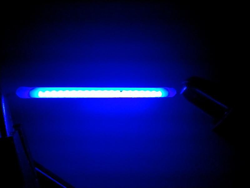
These cost around 30¢ each from AliExpress. They come in various lengths, from 20 mm to 68 mm; in various colours; and in various voltages, starting at 3 V. They are called hard filaments as opposed to the flexible fllaments that are even more decorative. They are smaller than you might expect from the photos which are larger than life-size. They are more like toothpicks in thickness. I picked 38 mm because that size could make a digit to fit within a 100x100 mm PCB, 12 V to reduce the current requirement, and three colours: red, green and blue.
I connected it up to the power supply I described in https://hackaday.io/page/398950-assembling-a-120-w-bench-power-supply which allows me to limit the current while cranking up the voltage.
I had questions I wanted answered:
- The scanty information on the webpages don't say if there is a current limiting resistor in the filament. I doubted it.
- The nominal voltage is 12 V but what is the current curve like as you increase the voltage? I didn't want to exceed the suggested limit of 45 mA.
- How come the different colours all have nominal voltages of 12 V? Do they use different junction meterials?
Increasing the voltage until the current limit of 45 mA was reached showed a filament voltage of just over 11 V. So it was as I suspected, there there is no resistor in the filament, and there are groups of 4 blue LEDs in series then in parallel all along the length of the filament for 4 junction drops, ~ 3 V x 4. Furthermore I'm sure that other colours are produced by phosphors excited by blue LEDs rather than different junction materials, different from single LED parts. Evidence in favour is that the blue filament is neutral white colour so that's the natural emission of the LEDs. These facts would explain why somebody measured a very high current feeding them from a 12 V supply. That I wanted to avoid as it would shorten the life.
So to use them for display purposes I need to devise a constant current circuit to limit the current. They are very bright so I should apply PWM to control the brightness. The other thing I have to do is devise a way of soldering the leads to the PCB. They are quite delicate and should not be bent more times than necessary.
-
Nearing the end of my AVR adventures
03/23/2025 at 08:34 • 0 comments![]()
AVR at the bare silicon level using my OOS (Old Old Stock) that is, because I still have a couple of Arduinos, but programming with them will be through the Arduino HAL which hides the low-level hardware stuff.
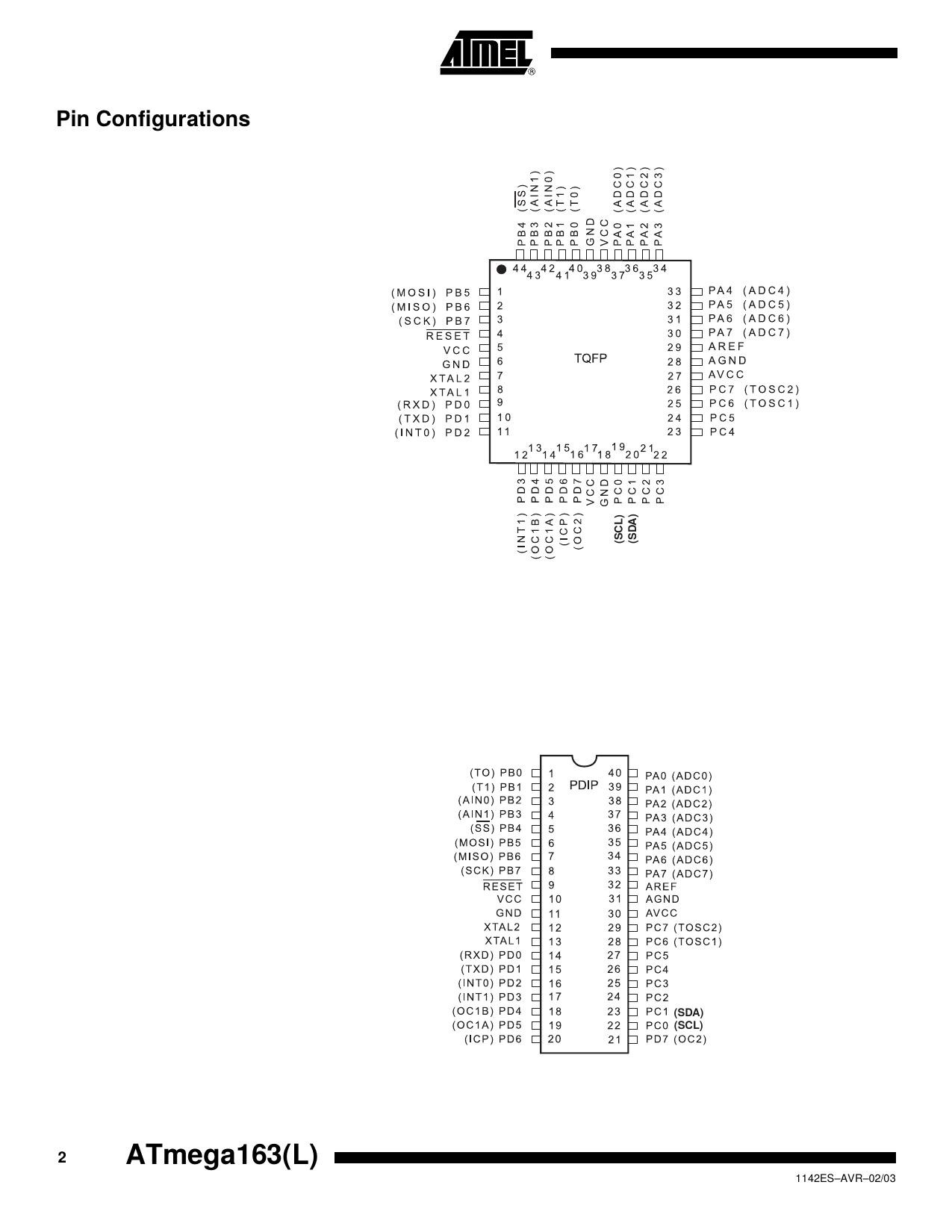
I found another AVR MCU in my junk box, and it's an ATMEGA163L. I was curious what modifications I would have to make to my build to compile code for it. Turns out, not much. Here's the section my Makefile which looks at the command line argument MCU=ATMEGA163 to choose different settings for the build.
MCU?=AT90S8515
CSRCS=clock.c ds3231.c i2c.c
BUILDFLAGS=-DX8_000_000 -DLOWON -DSIXSEGMENT -DRAISEDZERO # -DDS3231

ifeq "$(MCU)" "AT90S8515"
CSRCS+=at90s8515.c
BUILDFLAGS+=-DAT90S8515
# CRTs are inside the avr-gcc distribution
CRT=crtat90s8515.o
MCUOPT=-mmcu=avr2
endif

ifeq "$(MCU)" "ATMEGA163"
CSRCS+=atmega163.c
BUILDFLAGS+=-DATMEGA163
# CRTs are inside the avr-gcc distribution
CRT=crtatmega163.o
MCUOPT=-mmcu=avr5
endif
The MCU?=AT90S8515 establishes the default to be overriden by a command line assignment to MCU. The next two lines set the default source file list and BUILDFLAGS. As you can see the only things that change are the CRT startup file, a define that affects the source compiled, and the MCU architecture requested of the avr-gcc compiler. Fortunately the on-chip features I used are present in both MCUs. Atmel (now Microchip) did a decent job of family compatibility.
The 163 is the forerunner of the 164 which fixed some silicon bugs, hence not recommended for new designs. The L suffix means I have to change the declared crystal frequency to 4 MHz later. Unfortunately the 163/164 while still available in the DIP-40 package, have a different pinout from the AT90S8515. I'm loath to have 5 boards made only to use 1, or pay money for some NOS ATMEGA164s, so I might wire this up on perfboard (ugh!). I'll only need a 7805 regulator, a crystal and its load capacitors, a couple of bypass caps, and the reset RC circuit. I may live to regret using perfboard ☹️. We shall see.
-
A use for JLCPCB cardboard boxes
03/19/2025 at 07:08 • 0 comments![]()
Every 5 or 10 PCBs I order from JLCPCB I get a 15 x 15 cm cardboard box. I have accumulated many now. They are quite sturdy and a shame to put into paper recycling after one use.
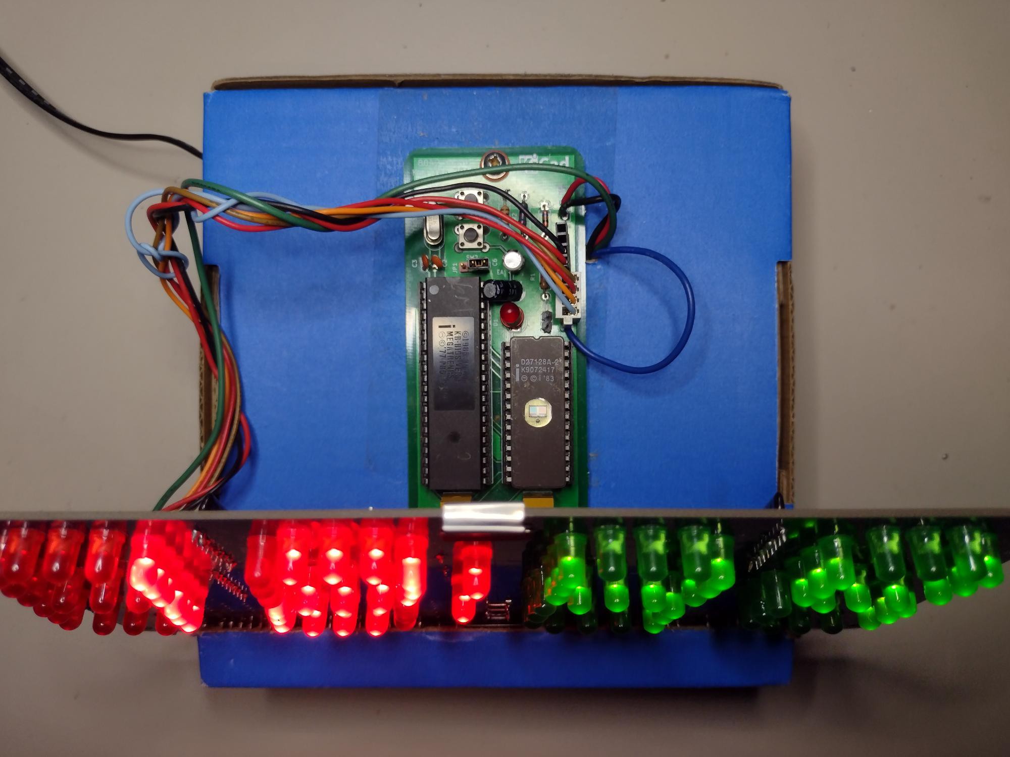
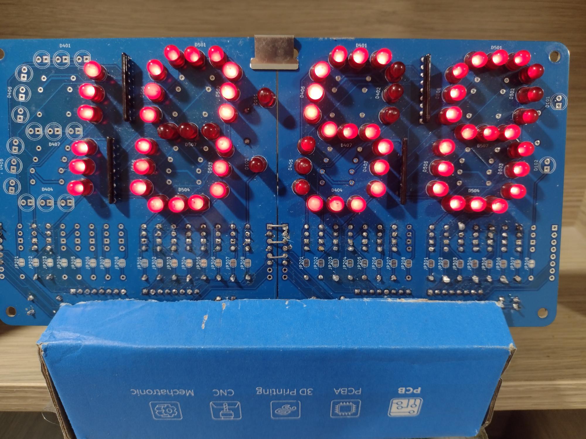
I think I now have a use for them. I cut a slightly slanting slot about 15° from the vertical from the top a few cm down the sides. Then I mounted quite recently designed boards from #Ancient 12 hour display there. The box is actually turned upside down and back to front, hence the discreet upside down logos on the front.
Here is the top view with the MCU module, although any MCU module will do. It's mounted outside because of the setting buttons. The power supply board is inside. It's supplied from a wall wart so low voltages.
![]()
I'll need to judiciously apply some hot glue to prevent joints and wires from going astray. Also to secure the clips at the middle top and bottom.
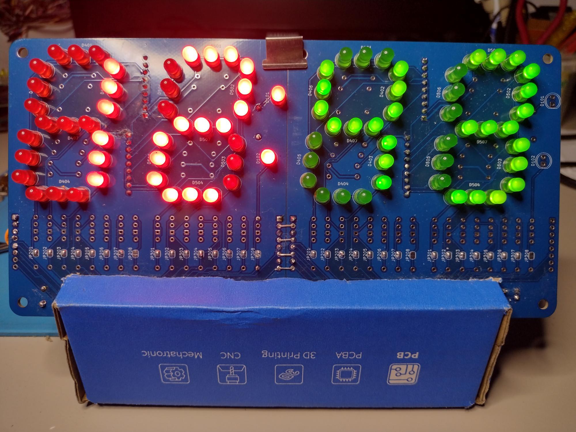
Another box. This is the clock from #Ancient 12 hour display
![]()
This project was not sponsored by JLCPCB. But I still thank them for the boxes. 🤣
My Projects
My Pages
Projects I Like & Follow
Share this profile
ShareBits
Become a Hackaday.io Member
Create an account to leave a comment. Already have an account? Log In.
Thank you for liking and following my #Prehistory of my homemade PERSEUS computers !
Thank you for following my Sol-20 Reproduction project Ken.
Hi Ken, thanks for the like for my TD4.
As far as a CPU it is pretty useless but it makes a great demo because of the flashing LEDs.
This seems to be a Japanese trait. When I was in Japan even the vending machines had animations. The TD4 book is half electronics and half anime imagery.
I am looking a more powerful 4 bit CPU in the same style as the TD4 (but for the prototype, using an IC PROM rather than a diode PROM). Only pencil drawings on graph paper at the moment.
Regards AlanX
A CPU with 11 TTL packages is interesting because I probably have all the parts needed but pity it doesn't do much more than flash LEDs. Looking forward to seeing your design.
Hi Ken,
I had a re-look at the TD4 and I had design a Paged version (https://cdn.hackaday.io/images/1250221502460302068.png) that increased the program space to 256x8. An ALU can be mapped in RAM space (16x4) but I did not pursue that option further (I could see better options).
Also an ALU (say an 181) could be connected to the A and B registers as inputs and the output directed to the "Zero Port". That is, replace "Move A,Z+Imm" with "Move A,ALU+Imm" etc. The Page register could be used as a function register for the ALU. The ALU would need to output Zero upon reset and to return to Zero under program control. Such is the problem with 4 bits is that you need more OpCode space.
Finally you could replace the original adder with an ALU and control the function with the Page register. You would need to be careful to be able to recover the CPU from a lock state. It was at this point I decided to build a new 4 Bit CPU from scratch.
Regards AlanX
Hi Ken,
I completely forgot, I have a redesigned TD4B version of the board (based on the one shown in my project posts: https://cdn.hackaday.io/images/5564921527557781106.png) but without the RAM and tidied up. It has not been tested (one day I will assemble it) but it should work. PM me if you want one.
AlanX
Thanks @agp.cooper
I'll think start small, with a zero bit CPU, just like I started learning juggling with zero balls. TBH I haven't progressed beyond that point. 🤣
Thank you for your comment to my #PERSEUS-8 homemade 6502 computer !
Thank you for liking my #Homemade Operational Amplifier and your comment !
Hi Ken, thanks for the like!
You've got a couple of nice projects, and I like your motto. Tinkering with electronics can be meditation.
Hello Ken, thanks for liking and following my new project, the Kobold computer, https://hackaday.io/project/164897-kobold-retro-ttl-computer !
Yes, obviously like me you appreciated the cleverness of the PDP-11 instruction set where the PC being R7, load immediate becomes load indirect R7 with autoincrement.
 Ken Yap
 Richard Testardi
 Anders Nielsen
 Guy Dupont
 Stefan Wagner
 Michael
 biemster
 CanHobby.ca
 Michael Wessel
 Anders Dinsen
 doctek
 Just4Fun
 BlackIoT SAGL
 Alan Boris
 Dan Julio
 yjmwxwx
 Frederico Souza Sant'ana
 Jay Riedl
 Rasmus L.


Hi Ken, thanks for liking my #Isetta TTL computer !