Commercially available DCF77 modules
- Conrad (receiver+antenna)
- HKW antenna + HKW receiver (datasheet)
- Grupo Premo antenna
- Reichelt (receiver+antenna)
- Universal Solder (receiver+antenna)
An evaluation of these DCF77 modules has been done by [Udo Klein] and can be found here.
Signal quality tests with HKW antenna & receiver
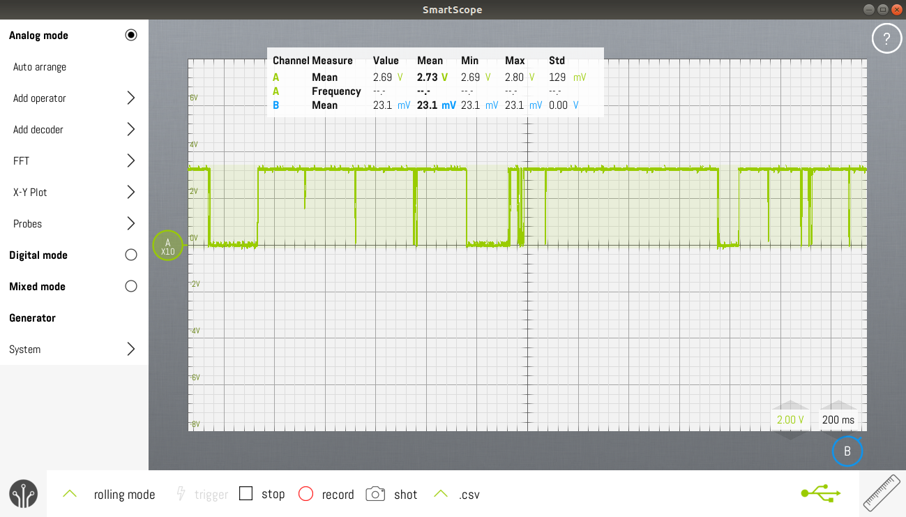
I hooked up the antenna to the receiver. The receiver was powered by a Protrinket3V, which in turn was powered by a TTL-232R-3V3-WE. The DCF output was monitored using a Smartscope.
At first, there was no useful signal. I pulled out all the mains plugs to find the culprit. I found three of them:
- USBwire lead of the TTL-232R-3V3-WE
- Asus charger for Asus X550L laptop (only when DC-jack is plugged into the laptop)
- Power adapter for Fantasia Xaro Desk light (EAN 5414358095390).
Moving the antenna closer to the window, away from these noise sources solves the problem.
I also discovered that signal quality can vary strongly during the day. During programming the signal went very bad. After a few minutes it turned all of a sudden to a good signal again. Nothing in my house was switched on or off during that instant.
The DCF77 Analyzer/Clock v2.also uses an external antenna and receiver. I also get the best results when the antenna and receiver are on one breadboard and the rest of the electronics are on another breadboard. There needs to be at least 30cm space between them. The antenna should also be kept at least 30cm away from the laptop.
Decoding time
Visual indication
The problem I quickly encountered is bad signal quality from the module. Rotating the antenna helps, but you can't ask from users to do this for you. A solution could be to add a mono stable multivibrator to the DCF output that triggers on falling edges. It could have a 500ms timeout. If you connect an LED to it, there would be a visual indication of signal quality. The user should see the LED flashing at a 1Hz rate. If the LED stays on or off then signal quality is bad.

[Udo Klein] put quite a lot of effort in providing an alternative in his Blinkenlight project. Unfortunately this project only works for AVR architectures. I forked the library and added support for the Bluepill. The other big drawback is that it takes at least 5 minutes to sink. With a bad signal, this can increase up to 30mins. The library of [Udo Klein] also requires you to synchronize your clock to the DCF77. If you don't do this, you won't be able to recover the signal from the noise when the signal goes bad.
Scientific papers about DCF77 decoding can be found here:
- Daniel Engeler Performance Analysis and Receiver Architectures of DCF77 Radio-Controlled Clocks (DRAFT) (pdf)
- Filip ZÁPLATA, Miroslav KASAL, Software Defined DCF77 Receiver, RADIOENGINEERING, VOL. 22, NO. 4, DECEMBER 2013 (pdf)
- Martin Wierich "Ein digitaler DCF77-Empfänger mit hoher Empfindlichkeit", Diplomarbeit (pdf)
Capturing data from serial port
minicom -D /dev/ttyACM0 -b 115200 -C minicom.cap
Displaying data
It's quite easy to use Calc/Excel to convert the capture file from minicom to two csv files, each containing one column.
These CSV-files can then be used as PWL input data for voltage sources.
[jafingerhut] has done quite some investigation about finding the right package to show your data.
Online decoded DCF data can be seen here.
 Christoph Tack
Discussions
Become a Hackaday.io Member
Create an account to leave a comment. Already have an account? Log In.