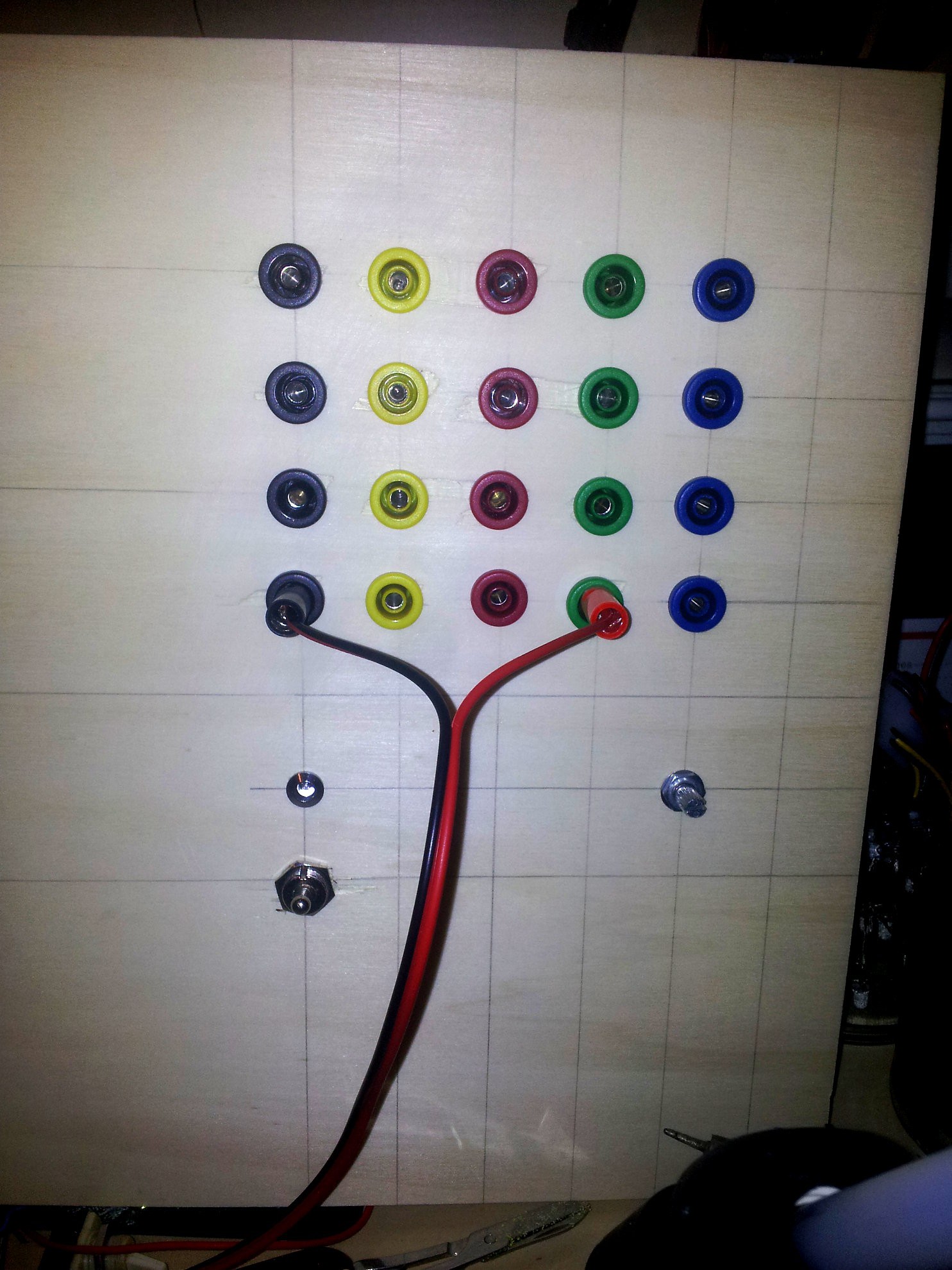
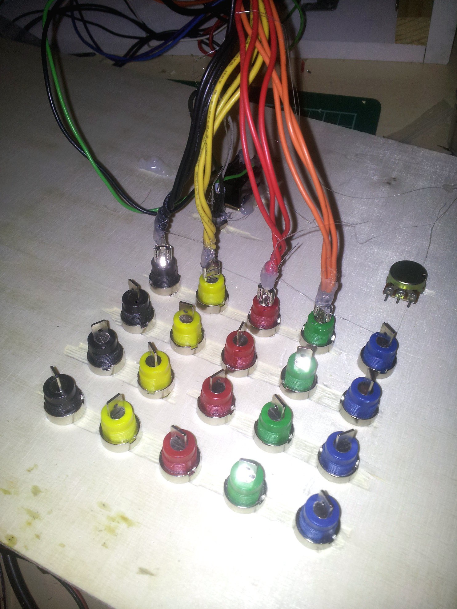
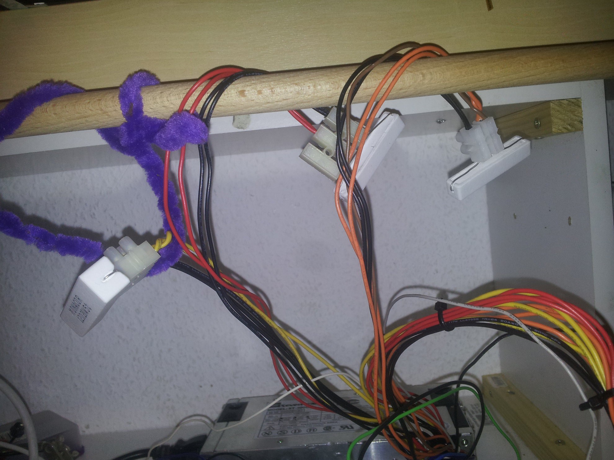
I guess I was a bit ÜBERmotivated. Excuse my german. So the plan was to get 4 ports with switchable voltages. But the connectors for banana plugs were that big, that I decided to use three wires on one.

This is definitely a temporary design, I've already worked on the 2nd version of it (with not so many banana plug terminals and will hopefully be able to get it laser cut somewhere. Maybe I'll throw in a USB plug.

The result so far... well... I got one port with 3/4 channels or the other way around. And maaaaaan, this old supply is loud.

I'm not sure how hot the resistors are allowed to get, but I'm planning some heat absorption and involving a fan to keep those monsters cool(er(ish)). The gauge of the wires is set to accept around 1.5A but I used 2 wires for safety reasons.
 davedarko
Discussions
Become a Hackaday.io Member
Create an account to leave a comment. Already have an account? Log In.
http://hackaday.com/2015/02/04/logic-noise-sweet-sweet-oscillator-sounds/
now that would be a cool addition to the 30cm x 70cm rack/box the PSU is in :)
Are you sure? yes | no
Are there some more details on V2 you're willing to share at this time? ;)
After building one based around the DP ATX BB with a LM2596 + cheap voltmeter, like yours, I found that I should have used one of those LM2596 boards with current control and matching ampere meter. I also should have used a 10k pot with 10 turns of travel to make adjustment of the voltage easier. Making the terminals/regulator detachable from the actual PSU really paid off once the first ATX PSU stopped working. Just some things to be aware of.
Do you really need that many power resistors? From what I read it was my understanding that you need them only on older PSUs because those require a load to turn on and also only on one rail. The ATX PSU I'm currently using isn't very recent either but still works without a load resistor and therefore isn't burning energy.
Even after seeing so many good ATX bench PSU projects I still find it interesting to check out the different ways people go about realizing it so I'm looking forward on seeing your finished idea ;)
Are you sure? yes | no
It's more a cosmetic setup for the V2. Basically giving it less ports. I may use them later for a pulse generator or an analog synth - its a 30x70cm box I build the things in, so there is some space for random stuff :) Current control and ampere meter sounds awesome, but I have this module and never used it, so finally using it seemed good. This pot sounds like a better option for controlling between 1.25V and 12V. This was all meant to be a recycling project, but I have to laugh about that, now that I have spend at least 30 euros. I'd love to have a pcb thing, where you plug in the ATX connector and everything works. Or at least I could get an ATX cable extender, cut/solder it and use this for switchable PSUs.
From my understanding, the resistors are for making sure that you get a stable voltage, so if you need stable 3.3V you need a load of 1A on there and same goes for 12V and 5V. The PSU is an older model and states minimal loads for each channel on the housing. I have a newer one where no minimal load was given, but I asked their support and they said that a minimal load of 0.5A would be required - while this can be reached easily with an arduino project, it doesn't have to.
I mainly steal ideas from others ;) Thanks for the input!
Are you sure? yes | no
I see, thanks for clarifying that there are min. loads on all rails. The box should be big enough such that you can increase the opening for the voltmeter to fit a combined voltage and current meter in the future should you need it.
I planned on writing a quick post giving a brief overview of my PSU and future improvements so maybe it's going to happen sooner than later to give you some more ideas ;)
(Also I feel like there should be a list here on had.io to collect ideas)
Are you sure? yes | no
that would be interesting to read :) some collective ideas to be worked on together would be cool.
Are you sure? yes | no
I soldered the potentiometer to the LM2596 today and tested it - you're totally right with the 10 turns - that would be a lot better. The voltmeter I have starts working at around 3.3V, so I freaked out a bit, when it was dark at first. I'm glad I worked on it, though.
Are you sure? yes | no
I think I'll use these in my next version: http://www.ebay.de/itm/171360636425?_trksid=p2060778.m1438.l2649&ssPageName=STRK%3AMEBIDX%3AIT
arent't even that expensive.
Your voltmeter has only two leads, right? I disassembled one of these to see if I could separate supply and sense voltage and it worked, now it goes down to approx. 1.2V. The modification even worked without taking off the display. I'll be sure to write about that as well but it won't be until the weekend though (last finals on Thursday and subsequent drinking will probably keep me from it. But hey, someone has to do it ;) ).
Are you sure? yes | no
What a relief! Good to know :) And thanks! Good luck on the finals and a happy reset :) I may print some gears to get some steampunk look with the copper colored chicken-head knob for the pot, but if that doesn't work out, I'll buy them.
Are you sure? yes | no