 danjovic
From an image posted on msx.org foruns,
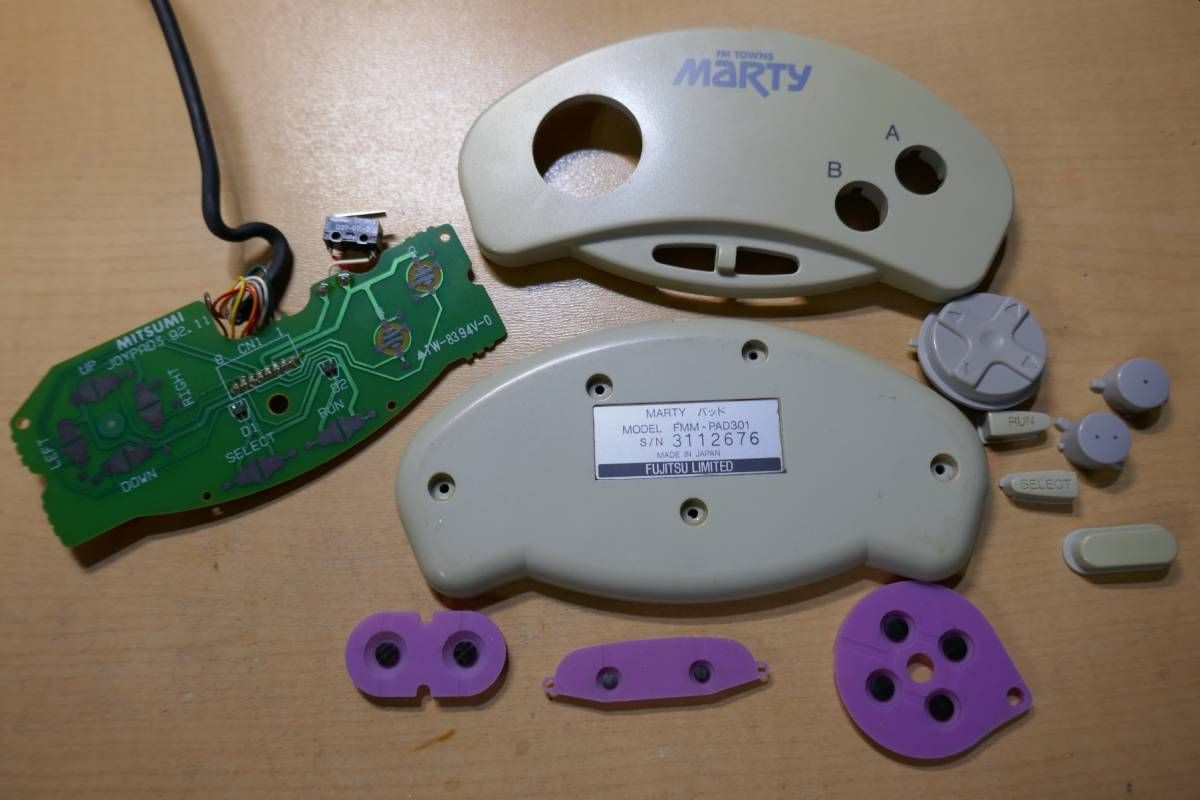
the following pinout was obtained:
Button    Pin(s)
UP          8
DOWN        5
LEFT        6
RIGHT       7
A           2
B           1
SEL         8/5 (through D1)
RUN         7/6 (through D2)
SW          4
COMMON      3
and the schematic was drawn:

finis!
From an image posted on msx.org foruns,
the following pinout was obtained:
Button Pin(s) UP 8 DOWN 5 LEFT 6 RIGHT 7 A 2 B 1 SEL 8/5 (through D1) RUN 7/6 (through D2) SW 4 COMMON 3
and the schematic was drawn:
finis!
Discussions
Become a Hackaday.io Member
Create an account to leave a comment. Already have an account? Log In.