-
STRW6053S: Everything You Need to Know
5 days ago • 0 commentsWhen it comes to power supply efficiency, the STRW6053S is a game-changer. But what makes this component so special? If you're looking for a reliable and efficient power switch IC, understanding its features, specifications, and applications can help you make an informed choice. In this article, we’ll break down everything you need to know about the STRW6053S in an easy-to-understand way.
What is STRW6053S?
The STRW6053S is an integrated power switch IC commonly used in switching power supplies. Designed for high efficiency and reliability, this component is widely used in various electronic devices to manage power conversion efficiently.
Key Features of STRW6053S
- High Efficiency: Reduces power loss and heat generation.
- Built-in Protection: Includes overcurrent, overvoltage, and thermal protection.
- Compact Design: Small form factor for easy integration.
- Low Power Consumption: Ensures energy savings and longer device life.
- Reliable Performance: Stable operation under varying loads.
Technical Specifications
- Input Voltage: Typically ranges from 85V to 265V AC
- Switching Frequency: ~100kHz
- Output Power: Varies depending on application
- Built-in MOSFET: Enhances efficiency and reduces external components
- Operating Temperature: -40°C to 125°C
How Does STRW6053S Work?
The STRW6053S operates as a power switch in AC-DC conversion. It regulates voltage by switching the internal MOSFET at high frequency, efficiently converting AC input into stable DC output. This ensures smooth power delivery while minimizing heat dissipation.
Applications of STRW6053S
This component is widely used in:
- Power Adapters: Ensures efficient voltage regulation.
- LED Drivers: Provides stable power to LED lighting.
- Industrial Power Supplies: Used in automation and control systems.
- Consumer Electronics: Found in TVs, computers, and audio systems.
Advantages of Using STRW6053S
- Energy Efficiency: Helps reduce electricity costs.
- Longer Lifespan: Protects circuits from damage.
- Cost-Effective: Reduces the need for additional components.
- Compact Design: Fits easily into various applications.
Installation and Usage Tips
- Ensure Proper Heat Dissipation: Use a heatsink if needed.
- Follow Manufacturer Guidelines: Stick to recommended input and output parameters.
- Check Circuit Compatibility: Ensure it meets voltage and current requirements.
Troubleshooting Common Issues
- Overheating: Ensure proper ventilation and heat sinking.
- No Output Voltage: Check input connections and load compatibility.
- Intermittent Power Loss: Verify circuit integrity and component placement.
Where to Buy STRW6053S?
You can purchase the STRW6053S from various online and offline suppliers, including:
- Electronics Retailers like Digi-Key, Mouser, and RS Components.
- Online Marketplaces like Amazon, eBay, and Alibaba.
- Local Electronics Stores offering industrial components.
Final Thoughts
The STRW6053S is a powerful and efficient power switch IC that offers a range of benefits for various applications. Whether you're working on power adapters, LED drivers, or consumer electronics, this component ensures optimal performance and longevity.
-
MAX232 Signal Conversion Explained: Essential Guide
02/28/2025 at 07:14 • 0 commentsWhen working with electronic communication systems, you might come across a situation where two devices need to talk to each other, but they speak in different "languages." This is where signal conversion comes in, and one of the most widely used components for this task is the MAX232. If you’ve ever wondered how computers, microcontrollers, or other devices communicate over long distances using serial ports, the MAX232 is likely at play, converting voltage levels so signals can travel between devices with different voltage requirements.
In this guide, we’ll explain how the MAX232 signal conversion works, why it’s important, and how it’s used in everyday technology. Whether you're an electronics hobbyist, a professional engineer, or just curious about how your devices communicate, this article will break down the essentials of the MAX232.
Introduction to Signal Conversion
Imagine you’re trying to make a phone call, but your phone speaks one language, and the person on the other end speaks a completely different one. For the conversation to happen, there needs to be someone—or something—that translates the message so both parties can understand it. In electronics, this “translator” is often a component called a signal converter.
Signal converters are essential when two devices need to communicate but use different types of signals. This happens frequently in serial communication systems where TTL (Transistor-Transistor Logic) signals and RS-232 signals need to be converted to each other. Enter the MAX232, an integrated circuit (IC) that does exactly this: it converts TTL to RS-232 and vice versa.
What is the MAX232?
The MAX232 is a widely used signal converter, specifically designed to translate voltage levels between TTL (0V and 5V) and RS-232 (±12V) serial communication protocols. It is a dual driver and receiver chip, meaning it can both send and receive signals. The MAX232 uses capacitors to generate the necessary voltage for RS-232 signals, which is higher than the standard TTL voltage.
In simple terms, the MAX232 allows modern devices, which use TTL signals (like microcontrollers or computers), to communicate with older devices that use RS-232 signals (like serial printers or modems). Without the MAX232, these devices wouldn't be able to understand each other, as their voltage levels are completely different.
Why is Signal Conversion Important?
Signal conversion is crucial because different devices and communication standards use varying voltage levels. A modern computer or microcontroller typically operates on TTL signals (low voltage, between 0V and 5V), whereas older communication systems like printers or industrial machinery use RS-232 signals, which use a higher voltage range (±12V).
If these devices were directly connected, there would be a risk of damaging one of them. The voltage from one system would either be too high or too low for the other device to process. Signal converters like the MAX232 bridge this gap safely and reliably, ensuring that devices can communicate without damage.
Understanding TTL and RS-232
Before diving deeper into how the MAX232 works, it’s essential to understand the two signal types it converts: TTL and RS-232.
TTL (Transistor-Transistor Logic)
TTL is a standard for digital electronics that uses 0V for logic low and 5V for logic high. This is the common voltage range for modern microcontrollers, such as Arduino or Raspberry Pi, as well as other digital circuits.
RS-232
RS-232, on the other hand, is a serial communication standard used for long-distance data transmission. It uses voltage levels like +12V to indicate a logic low and -12V to indicate a logic high. RS-232 signals are more robust and can travel longer distances compared to TTL signals, but they are not compatible with modern low-voltage digital systems.
How the MAX232 Converts Signals
The MAX232 works by converting the TTL signal’s voltage (0V to 5V) to the RS-232 voltage range (±12V), and...
Read more -
547 Transistor Equivalent: Finding the Right Replacement
02/08/2025 at 07:49 • 0 commentsThe BC547 NPN transistor is widely used in electronics due to its versatility and reliability. However, there are times when you need a replacement due to availability, performance, or specific circuit requirements. So, what are the best 547 transistor equivalents? Let's explore the best alternatives and how to choose the right one for your needs.
Understanding the BC547 Transistor
The BC547 is an NPN bipolar junction transistor (BJT) commonly used in switching and amplification applications. It is known for its low power consumption and high reliability.
Why Would You Need an Equivalent?
There are several reasons why you might need a BC547 equivalent:
- Availability Issues: The BC547 might be out of stock.
- Performance Needs: Some circuits require transistors with higher voltage or current ratings.
- Cost Considerations: Some equivalents might be more affordable.
- Upgrading Older Circuits: More efficient alternatives may enhance circuit performance.
Key Specifications of BC547
Before choosing a replacement, it's important to know the key specs of the BC547:
- Type: NPN BJT
- Maximum Voltage (Vce): 45V
- Maximum Current (Ic): 100mA
- Power Dissipation: 500mW
- HFE (Gain): 110-800
- Package: TO-92
How to Choose the Right Replacement
To pick the right BC547 equivalent, consider:
- Voltage Rating: Ensure the replacement supports the required voltage.
- Current Rating: If your circuit requires higher current, opt for S8050 or 2N3904.
- HFE (Gain): If gain is critical, ensure the replacement has a similar range.
- Package Compatibility: Check if the alternative fits your PCB layout.
Application Areas of BC547 and Its Equivalents
The BC547 and its equivalents are commonly used in:
- Audio Amplifiers
- Switching Circuits
- Signal Processing
- Microcontroller Interfacing
- Sensor Circuits
Circuit Considerations When Replacing BC547
- Pin Configuration: Some equivalents might have different pinouts.
- Biasing Requirements: Verify that the biasing resistors are suitable for the new transistor.
- Power Dissipation: Higher power dissipation can affect circuit stability.
Common Mistakes When Using Equivalents
Avoid these common mistakes:
- Ignoring Maximum Ratings: Using a transistor with lower voltage or current limits can cause failures.
- Overlooking Gain Differences: Significant gain variations can impact performance.
- Wrong Pin Configuration: Always check the datasheet for pin assignments.
Where to Buy BC547 and Its Equivalents?
You can purchase these transistors from online stores like:
- Digi-Key
- Mouser Electronics
- OvagaConclusion
Finding the right BC547 transistor equivalent is easy if you match key specifications like voltage, current, gain, and package type. Whether you're replacing the BC547 due to availability, performance needs, or cost, there are several great alternatives like the BC548, 2N3904, and S8050 to choose from. Always double-check your circuit requirements before making a substitution.
-
XA7A25T-1CPG238Q: Part of the Artix-7 Family
01/14/2025 at 05:54 • 0 commentsThe world of technology is growing at an incredible pace, and one of the unsung heroes behind this evolution is the FPGA (Field-Programmable Gate Array). Among these, the XA7A25T-1CPG238Q, a member of the Artix-7 family from Xilinx, stands out. Whether you're a tech enthusiast or just curious about what makes our gadgets smarter, this article will guide you through the exciting details of this remarkable chip in a simple and engaging way.
Introduction to the XA7A25T-1CPG238Q
Have you ever wondered how modern gadgets like drones or smart TVs make such rapid decisions? Devices like the XA7A25T-1CPG238Q are the brains behind this speed and efficiency. This FPGA is not just any ordinary chip; it's designed to handle complex tasks while consuming minimal power.
What is an FPGA?
An FPGA, or Field-Programmable Gate Array, is like a blank slate for engineers. Imagine it as a box of LEGO blocks. You can assemble these blocks into a robot today and a car tomorrow. Similarly, an FPGA can be reprogrammed to perform various tasks, making it incredibly versatile.
Overview of the Artix-7 Family
The Artix-7 family is Xilinx's answer to the demand for high-performance chips that don’t guzzle power. These FPGAs strike the perfect balance between performance, power, and price, making them ideal for a wide range of applications. The XA7A25T-1CPG238Q is one such model that offers robust capabilities for industries like automotive, communications, and more.
Key Features of the XA7A25T-1CPG238Q
- Low Power Consumption: Designed to maximize efficiency.
- High Performance: Enables quick data processing.
- Programmability: Tailored to meet specific application needs.
- Compact Design: Fits seamlessly into various devices.
Performance and Power Efficiency
The XA7A25T-1CPG238Q shines when it comes to doing more with less. It’s engineered to deliver outstanding performance without draining power, making it a favorite for battery-operated devices.
Applications Across Industries
This FPGA isn’t limited to one niche. Here’s where you’ll find it making an impact:
- Automotive: Powering advanced driver-assistance systems (ADAS).
- Communications: Enhancing signal processing in telecom equipment.
- Medical Devices: Supporting precise imaging and diagnostics.
- Consumer Electronics: Improving performance in smart gadgets.
Advantages of the XA7A25T-1CPG238Q
Why is this chip gaining traction?
- Cost-Effective: Offers a great mix of features at an affordable price.
- Durability: Designed for reliable operation in challenging environments.
- Flexibility: Adapts easily to evolving technological needs.
Comparison with Other Artix-7 Models
While the Artix-7 family is known for its quality, the XA7A25T-1CPG238Q stands out for its balance between power and performance. Other models may prioritize extreme performance or ultra-low power, but this one nails the sweet spot.
Why Choose the XA7A25T-1CPG238Q?
If you’re looking for an FPGA that’s adaptable, efficient, and capable of handling demanding tasks, this model is hard to beat. Its ability to perform in diverse applications makes it a go-to for developers worldwide.
Environmental and Industrial Use
The rugged design of the XA7A25T-1CPG238Q allows it to thrive in extreme temperatures and tough conditions. Whether it's a factory floor or a remote desert, this chip performs flawlessly.
Future Trends with Artix-7 FPGAs
As technology continues to advance, the demand for efficient and adaptable chips like the XA7A25T-1CPG238Q will only grow. Its design aligns perfectly with trends like IoT (Internet of Things) and AI-driven applications.
-
Everything You Need to Know About STM32L152RBT6
12/27/2024 at 09:43 • 0 commentsHave you ever wondered what powers some of the smart devices we use daily? Meet the STM32L152RBT6 – a tiny yet powerful microcontroller that makes innovation possible. Whether you're an engineer, hobbyist, or just curious about technology, this guide will give you a clear picture of why this microcontroller is a big deal. Think of it as the brain behind your favorite gadgets, working tirelessly while sipping energy.
Ready to dive in? Let’s explore the STM32L152RBT6 in detail, breaking down its features, uses, and why it stands out in the world of electronics.
1. Overview of STM32L152RBT6
The STM32L152RBT6 is part of the STM32L1 series from STMicroelectronics, known for its ultra-low-power microcontrollers. It’s built on an ARM Cortex-M3 core, designed to deliver impressive performance while consuming minimal energy. With a 32-bit architecture, this microcontroller is perfect for applications requiring precision and efficiency.
2. Key Features
- Low Power Consumption: Ideal for battery-operated devices.
- High Performance: ARM Cortex-M3 core running up to 32 MHz.
- Integrated Peripherals: Includes timers, ADCs, and communication modules.
- Rich Memory Options: 128KB Flash, 16KB RAM, and an integrated EEPROM.
- Temperature Range: Operates reliably between –40°C to +85°C.
These features make the STM32L152RBT6 a versatile choice for a wide range of projects.
3. Pin Configuration and Functions
This microcontroller comes in a 64-pin LQFP package, with each pin serving a specific purpose. Here’s a quick breakdown:
- Power Pins: For VDD and VSS connections.
- GPIO Pins: Configurable for input, output, or alternate functions.
- Communication Pins: Support for USART, I2C, and SPI interfaces.
- Analog Pins: Linked to ADC and DAC for signal processing.
4. Low-Power Capabilities
One of the standout features of the STM32L152RBT6 is its ultra-low-power modes. It offers several power-saving options, including:
- Sleep Mode: Reduces power consumption while maintaining essential operations.
- Stop Mode: Almost halts all activities but retains data in RAM.
- Standby Mode: Consumes the least power, ideal for long-term battery life.
These modes are crucial for IoT devices and wearables where battery longevity is essential.
5. Memory Architecture
The STM32L152RBT6 offers a well-structured memory system:
- Flash Memory: 128KB for storing programs and firmware.
- RAM: 16KB for temporary data storage during operations.
- EEPROM: Non-volatile memory for saving configuration settings.
This combination ensures fast performance and reliable data retention.
6. Peripherals and Interfaces
Peripherals and interfaces enhance the microcontroller’s functionality, such as:
- Analog Features: 12-bit ADC, DAC, and comparators for handling analog signals.
- Timers: Basic, general-purpose, and advanced timers for time-sensitive tasks.
- Communication Protocols: I2C, SPI, USART, and USB for device connectivity.
- LCD Driver: Supports up to 8x40 or 4x44 segments for display control.
7. Performance and Efficiency
Despite its low power consumption, the STM32L152RBT6 delivers reliable performance:
- Core Processing: The ARM Cortex-M3 core ensures swift task execution.
- Interrupt Handling: Quick response to external events.
- Scalability: Balances performance and energy efficiency for versatile use cases.
8. Applications in Modern Devices
The STM32L152RBT6 is a favorite in industries like:
- Wearables: Fitness trackers and smartwatches.
- Medical Devices: Portable monitors and diagnostic tools.
- Home Automation: Smart thermostats and security systems.
- Industrial Sensors: Low-power data acquisition units.
Its adaptability makes it a go-to solution for designers and engineers.
9. Development Tools and Ecosystem
STMicroelectronics provides a robust ecosystem for the STM32 series:
- Integrated Development Environments (IDEs): Such as STM32CubeIDE.
- Firmware Libraries: STM32CubeL1 offers pre-built libraries.
- Debugging Tools: On-chip debugging through SWD and JTAG.
- Community Support: Extensive forums and documentation....
-
ULN2003AIPWR Darlington Transistor Array: The Ultimate Guide
12/03/2024 at 08:14 • 0 commentsWhen it comes to controlling high-power devices using low-power signals, the ULN2003AIPWR Darlington transistor array is one of the most reliable and commonly used components in electronics. Whether you're a hobbyist, an engineer, or someone interested in understanding how modern electronic systems work, this transistor array is worth knowing about. But what makes it so special? How does it work, and how can you use it in your own projects? In this guide, we will explore everything there is to know about the ULN2003AIPWR, from its basic functionality to its applications and common use cases.
What is the ULN2003AIPWR Darlington Transistor Array?
The ULN2003AIPWR is a Darlington transistor array integrated circuit (IC) used primarily to interface low-voltage microcontrollers or logic circuits with high-voltage loads. It's a versatile and cost-effective component that allows a small signal from a microcontroller to switch larger devices, such as motors, relays, and lamps, on or off.
Think of it as a bridge that connects the delicate, low-power world of microcontrollers to the high-power devices that require more juice to operate. In short, it’s a power amplifier that takes small signals and turns them into much larger ones—enabling devices like motors and relays to work without a hitch.
Understanding the Basics of Darlington Transistors
Before diving into how the ULN2003AIPWR works, it’s important to understand what a Darlington transistor is. A Darlington transistor is essentially two transistors combined in a single package to provide a higher gain, meaning it can amplify signals more effectively. The first transistor amplifies the input signal, and the second transistor further amplifies the output of the first. The result is a very high amplification of the initial signal.
In the case of the ULN2003AIPWR, there are seven Darlington pairs in a single IC, each capable of handling up to 500mA of current. This makes it ideal for driving various devices that require more power than a typical microcontroller can provide.
Key Features of ULN2003AIPWR
The ULN2003AIPWR is packed with useful features that make it a go-to choice for many electronic designs:
- Seven Channels: It has seven Darlington pairs, each capable of handling up to 500mA of current, making it useful for controlling multiple devices simultaneously.
- Built-in Flyback Diodes: These diodes protect the IC from voltage spikes, which are common when controlling inductive loads like motors and relays.
- Low-Voltage Control: The ULN2003AIPWR is designed to work with low-voltage inputs, making it compatible with most logic circuits and microcontrollers.
- Easy to Use: It simplifies the process of controlling high-power devices by providing an easy interface between low-power logic circuits and high-power loads.
These features make it a popular choice in various applications, from robotics and home automation to industrial control systems.
How Does the ULN2003AIPWR Work?
To understand how the ULN2003AIPWR works, let's break it down into simple steps:
- Input Control Signals: The microcontroller or logic circuit sends a small signal (often 5V or 3.3V) to the input pins of the ULN2003AIPWR.
- Amplification: The Darlington transistors inside the ULN2003AIPWR amplify the input signal. This is where the Darlington configuration comes into play, allowing the IC to handle larger currents.
- Output to High-Power Load: The amplified signal is then used to drive a high-power device, such as a motor, relay, or other load, through the output pins.
- Protection: Built-in flyback diodes ensure that any voltage spikes from inductive loads do not damage the IC or the connected components.
In essence, the ULN2003AIPWR acts as a signal amplifier and switch, making it possible for your microcontroller to control high-power devices with ease.
Applications of ULN2003AIPWR in Electronics
The ULN2003AIPWR is used in a wide variety of applications. Some of the most common include:
- Motor Control: Used in robotics,...
-
Why the BAS16HT1G Diode is Reliable for Circuits
11/14/2024 at 06:03 • 0 commentsWhen designing circuits, choosing reliable components is key to creating systems that last. Among these, the BAS16HT1G diode is known for its dependability, playing a critical role in ensuring consistent performance. But what makes this diode so reliable, and why is it a trusted choice in many circuits? In this article, we’ll explore its unique benefits, how it works, and why it might be the perfect fit for your next project.
What is the BAS16HT1G Diode?
The BAS16HT1G is a small-signal diode known for its efficiency and durability. Unlike larger components, it’s designed to handle low currents and voltage, making it ideal for small, sensitive circuits.
Importance of Reliability in Circuit Design
Imagine driving a car with an unreliable engine—it’s bound to fail at the worst moment. Similarly, in electronics, components like diodes must function consistently to ensure overall system reliability.
Core Features of the BAS16HT1G
- Low Forward Voltage Drop: Helps in efficient power management.
- High Switching Speed: Ideal for fast-paced electronic environments.
- Compact Design: Fits seamlessly into even the smallest circuits.
- High Temperature Tolerance: Ensures stability in variable conditions.
How the BAS16HT1G Diode Works in a Circuit
The BAS16HT1G diode functions by allowing current to flow in one direction, preventing any backflow. This property is vital in protecting other sensitive components from unintended current directions.
Voltage and Current Capabilities of the BAS16HT1G
Designed for low current and voltage applications, the BAS16HT1G has specific thresholds that make it ideal for precise circuits, ensuring it won't overload sensitive components.
Applications of the BAS16HT1G Diode
This diode is commonly found in:
- Signal Processing Circuits
- Protection Circuits
- Rectification in Small Devices
- Switching Applications
BAS16HT1G vs. Other Diodes
Compared to other diodes, the BAS16HT1G offers a unique blend of speed and durability, standing out particularly in high-speed and low-current applications.
Benefits of Using the BAS16HT1G for Reliability
- Consistency: The BAS16HT1G maintains steady performance, reducing the need for frequent replacements.
- Protection: Helps safeguard other components by blocking reverse current.
- Efficiency: Optimizes power usage, which is essential in battery-powered devices.
Selecting the BAS16HT1G for Your Project
To decide if this diode fits your needs, assess your circuit’s current, voltage requirements, and space constraints. The BAS16HT1G is often chosen for its compact form and high reliability.
Thermal Management and Longevity
Diodes generate heat, which, if unchecked, can shorten their lifespan. With the BAS16HT1G, ensuring adequate ventilation or cooling can greatly extend its performance.
Common Issues and Troubleshooting Tips
If you’re facing issues with voltage drop or current flow, it may be due to improper installation or circuit mismatch. Ensure that connections are secure and voltages are within safe limits.
Ensuring Safe and Efficient Operation
For the BAS16HT1G to operate at its best, avoid exceeding its voltage and current ratings, and handle it carefully to avoid physical stress.
Advances in Diode Technology
Diodes continue to evolve, becoming more efficient and reliable. The BAS16HT1G is part of this trend, showing how small components can handle significant workloads with reliability.
Conclusion
The BAS16HT1G diode stands out for its dependability, efficient power management, and ability to fit within small circuits. Whether you’re working on a personal project or developing professional-grade electronics, this diode offers the stability and durability needed to keep your circuits running smoothly.
-
C8051F120 vs PIC18F4550: Key Differences
11/06/2024 at 07:36 • 0 commentsChoosing the right microcontroller can be challenging with so many options available. In this article, we’ll compare two popular microcontrollers – the C8051F120 and the PIC18F4550 – and break down their differences. Whether you're a hobbyist or a professional, understanding these distinctions will help you make the best choice for your project.
What Are Microcontrollers?
In simple terms, a microcontroller is a tiny computer embedded in devices to control specific functions. They power everything from household appliances to sophisticated industrial equipment.
Overview of C8051F120 and PIC18F4550
The C8051F120 is a high-performance microcontroller from Silicon Labs, known for its speed and rich set of peripherals. The PIC18F4550, on the other hand, is a popular model from Microchip, appreciated for its USB capabilities and affordability. Let’s dive into what sets them apart.
Processing Speed and Performance
When it comes to speed, the C8051F120 has a clear edge, operating at 100 MIPS (Million Instructions Per Second), thanks to its highly optimized 8051 core. In comparison, the PIC18F4550 runs at around 12 MIPS. If your application requires rapid processing – like in real-time data handling – the C8051F120’s faster speed can make a noticeable difference.
Power Efficiency
The C8051F120 and PIC18F4550 both offer power-saving features, but they differ in their approach. The C8051F120 provides several low-power modes, allowing it to conserve energy when full processing isn’t required. The PIC18F4550 also offers sleep modes and is generally known for being energy-efficient in USB-based applications.
Memory Capacity
The memory capabilities of each microcontroller vary:
- C8051F120: Comes with 128 KB flash memory and 8 KB RAM, ideal for applications needing significant code and data storage.
- PIC18F4550: Has 32 KB flash memory and 2 KB RAM, which is typically sufficient for simpler applications.
If your project involves complex code or larger data storage, the C8051F120’s larger memory offers a clear advantage.
Peripheral Features
The C8051F120 boasts an impressive array of built-in analog and digital peripherals, such as 12-bit ADCs (Analog-to-Digital Converters), DACs (Digital-to-Analog Converters), and PWM (Pulse Width Modulation) channels. The PIC18F4550 includes USB connectivity, which can be a game-changer for USB-based applications like data logging devices or computer peripherals.
Ease of Programming and Debugging
Programming ease often influences a microcontroller’s popularity. The C8051F120 has advanced on-chip debugging features, allowing real-time testing, which reduces development time. The PIC18F4550, while also supporting debugging, has a simpler setup that’s often preferred by beginners or those working on less complex projects.
Compatibility and Integration
The C8051F120 is highly versatile, integrating well in various systems due to its broad range of communication interfaces. The PIC18F4550 is compatible with many Microchip tools and interfaces, making it popular in both educational settings and commercial USB applications.
Cost and Availability
Cost is always an important factor. The PIC18F4550 is generally more affordable and widely available, making it accessible for hobbyists and educational use. The C8051F120 is more expensive, often chosen by professionals who prioritize high performance over cost.
Application Suitability
Each microcontroller has unique strengths:
- C8051F120: Suited for industrial automation, healthcare, and consumer electronics where speed and precision are paramount.
- PIC18F4550: Great for USB-based applications, educational projects, and cost-sensitive designs.
Pros and Cons of C8051F120
Pros:
- High-speed processing (100 MIPS)
- Rich set of built-in peripherals
- Large memory capacity (128 KB flash)
Cons:
- Higher cost
- Slightly more complex for beginners
Pros and Cons of PIC18F4550
Pros:
- USB connectivity
- Cost-effective
- Beginner-friendly
Cons:
- Lower processing speed
- Limited memory...
-
Jotrin Electronics on Crunchbase: A Deep Dive into the Company’s Growth
10/10/2024 at 08:27 • 0 commentsWhen you're searching for a company’s background and growth potential, Crunchbase is often the go-to platform. One company that has caught the attention of many in the electronics industry is Jotrin Electronics. As a leading provider of electronic components and semiconductors, Jotrin Electronics has a prominent presence on Crunchbase, showcasing its journey, partnerships, and impact in the global electronics market.
But what exactly does Crunchbase tell us about Jotrin Electronics? How does it position itself among other players in the electronics distribution space? In this article, we’ll explore Jotrin’s profile on Crunchbase and uncover key insights about the company’s operations, history, and growth trajectory.
Introduction
In today’s digital world, finding accurate information about a company is essential, especially when it comes to making purchasing or partnership decisions. Jotrin Electronics is a well-known player in the electronic components market, and its profile on Crunchbase offers valuable insights into its operations, funding, and business growth.
This article will give you a comprehensive understanding of Jotrin’s standing on Crunchbase, highlighting important aspects of the company, such as its history, products, global reach, and more.
What is Crunchbase?
Before diving into Jotrin’s profile, it’s important to understand what Crunchbase is. Crunchbase is an online platform that provides information about businesses, including their financials, funding rounds, partnerships, and business activities. It is widely used by entrepreneurs, investors, and businesses to research companies, track trends, and discover opportunities.
Why Use Crunchbase for Research?
Crunchbase provides a transparent overview of a company’s growth trajectory, making it an excellent tool for anyone looking to gauge a company’s success, partnerships, and potential. Whether you are an investor or simply curious about a company, Crunchbase is a reliable source of information.
Jotrin Electronics Overview on Crunchbase
Jotrin Electronics has a detailed and comprehensive profile on Crunchbase. The company is categorized under Electronics and Semiconductors, reflecting its specialization in distributing electronic components globally.
Basic Company Information
Jotrin’s Crunchbase profile includes all the essential details, such as the company’s website, headquarters location, contact information, and a summary of its business operations. It also lists employees, showcasing the size of the company and the different roles within the organization.
Company History and Founding
One of the highlights of Jotrin’s Crunchbase profile is its detailed history and founding story. Established with the goal of making electronic components accessible to engineers and manufacturers worldwide, Jotrin has grown from a small operation into a major distributor.
Milestones and Achievements
Over the years, Jotrin has expanded its product offerings, customer base, and geographic reach. Their Crunchbase profile often highlights key milestones, such as opening new offices, launching new product lines, or securing important partnerships.
Business Model and Services
Jotrin’s business model revolves around the distribution of electronic components. They serve industries like consumer electronics, automotive, aerospace, and more. The company’s services are highlighted on Crunchbase, including its focus on offering hard-to-find components, quick shipping, and excellent customer service.
How Does Jotrin Stand Out?
What makes Jotrin stand out from competitors is its commitment to quality assurance and its ability to source rare components that may not be available through other suppliers. This is a significant advantage for engineers and manufacturers working on specialized projects.
Key Products and Offerings
Jotrin’s Crunchbase profile also outlines their core products. They offer a wide range of semiconductors, microcontrollers, capacitors, connectors, and...
Read more -
Understanding the BAT54C-7-F Schottky Diode: Key Specs
09/13/2024 at 03:24 • 0 commentsSchottky diodes are essential components in modern electronics, known for their low forward voltage drop and fast switching capabilities. Among these, the BAT54C-7-F Schottky diode stands out as a popular choice for various applications. In this article, we will break down its key specifications and features to understand what makes it so widely used.
What is the BAT54C-7-F Schottky Diode?
The BAT54C-7-F is a dual Schottky diode in a common cathode configuration, designed for low voltage and high-speed switching applications. It operates effectively in systems where efficient energy use and fast response times are critical.
Schottky diodes like the BAT54C-7-F differ from regular diodes by using a metal-semiconductor junction rather than a traditional P-N junction. This design minimizes the forward voltage drop and increases switching speed, making them ideal for high-frequency applications.
![]()
Key Specifications of BAT54C-7-F
1. Forward Voltage (VF)
One of the standout features of Schottky diodes is their low forward voltage drop. For the BAT54C-7-F, the forward voltage ranges between 0.24V and 0.32V when conducting 1mA of current. At higher currents, such as 100mA, the forward voltage drop can rise to around 0.80V.
This low forward voltage results in minimal power loss, making the BAT54C-7-F a great option for power-sensitive applications.
2. Reverse Voltage (VR)
The BAT54C-7-F is rated for a maximum reverse voltage (VR) of 30V. This means it can block voltages of up to 30V in the reverse direction without conducting. It ensures that the diode can safely operate in low-voltage systems without the risk of reverse current leakage.
3. Reverse Leakage Current (IR)
Another important spec is the reverse leakage current, which is the small amount of current that can leak through the diode when it is reverse-biased. For the BAT54C-7-F, the reverse leakage current is typically 2 µA at 25°C. This low leakage current helps maintain circuit efficiency.
4. Maximum Average Forward Rectified Current (IF)
The BAT54C-7-F can handle a maximum average forward rectified current of 200mA. This makes it suitable for low to moderate current applications where high efficiency and fast switching are needed.
5. Power Dissipation (PD)
The power dissipation rating for the BAT54C-7-F is 200mW. This ensures that the diode can handle typical power levels without overheating, contributing to its reliability in various applications.
Package Type: SOT-23
The BAT54C-7-F comes in a SOT-23 package, a small and compact surface-mount package commonly used in space-constrained designs. The SOT-23 package allows the diode to be easily integrated into circuits with minimal footprint, making it ideal for modern, compact electronic designs like mobile devices and portable gadgets.
Applications of BAT54C-7-F Schottky Diode
1. Power Supply Circuits
The low forward voltage drop of the BAT54C-7-F ensures that power losses are minimized in rectification circuits, particularly in switch-mode power supplies (SMPS). It is often used in DC-DC converters, where efficient power conversion is critical.
2. High-Speed Switching
Schottky diodes are known for their fast switching speeds, and the BAT54C-7-F is no exception. This makes it ideal for high-frequency switching applications such as clamping diodes and protection circuits.
3. Reverse Voltage Protection
The BAT54C-7-F can also be used in circuits that need reverse voltage protection, preventing damage to sensitive components if the power supply polarity is accidentally reversed.
4. RF Circuits
In RF applications, Schottky diodes are often used for their ability to handle high-frequency signals without significant losses. The BAT54C-7-F’s low capacitance makes it suitable for use in RF signal detection and mixing circuits.
Conclusion
The BAT54C-7-F Schottky diode is a versatile and efficient component that excels in power-sensitive, high-speed applications. Its low forward voltage drop, high switching speed,...
Read more -
Top FPGA Development Tools for Efficient Design
09/05/2024 at 07:03 • 0 commentsIntroduction to FPGA Development Tools
If you’re familiar with hardware design, you know that FPGAs offer unmatched flexibility. But designing for FPGAs requires more than just coding knowledge—you need the right tools to bring your vision to life. In this article, we’ll explore the best FPGA development tools that both professionals and beginners can use to efficiently design, simulate, and optimize their FPGA-based projects.
Why Choosing the Right FPGA Tool Matters
Selecting the right FPGA tool can make or break your project. Imagine you’re building a house; having the right construction tools is just as important as knowing how to use them. The same applies to FPGA development. The tools you choose will affect how easily you can design, simulate, and test your FPGA, ensuring that the hardware behaves exactly as you expect.
Xilinx Vivado Design Suite: A Comprehensive Solution
Xilinx Vivado is widely regarded as one of the top FPGA design tools in the market, primarily for Xilinx FPGA products. It offers a complete design environment that supports the entire process—from design entry and synthesis to implementation and verification. Vivado stands out for its intuitive interface, making it easier for designers to work on complex designs.
- Key Features:
- Block-based design
- High-level synthesis (HLS)
- Power analysis tools
- IP integration
- Ideal for large-scale FPGA designs requiring high performance.
Intel Quartus Prime: Flexible and Versatile
Another heavy hitter in the FPGA world is Intel's Quartus Prime. Quartus Prime offers a flexible platform for designing and optimizing Intel FPGAs, providing everything you need for FPGA design, from simulation to hardware debugging. Quartus Prime supports a range of Intel devices and provides a user-friendly interface for both new and experienced designers.
- Key Features:
- Support for multiple FPGA families
- Fast simulation and verification tools
- Integrated DSP and IP cores
- Scripting automation
Quartus Prime makes it easy to design even the most intricate hardware, providing flexibility at every stage of development.
Lattice Diamond: Low-Power Design Focus
For those working on low-power applications, Lattice Diamond is a standout choice. It’s specifically designed for Lattice Semiconductor’s FPGAs and focuses on power-efficient designs. The tool provides comprehensive support for designing, debugging, and optimizing low-power FPGA applications.
- Key Features:
- Low-power optimization
- Power estimation tools
- Drag-and-drop interface
- In-system debugging tools
Lattice Diamond is perfect for energy-sensitive applications, making it a top choice for IoT, wearable devices, and battery-powered projects.
Altera ModelSim: Powerful Simulation Environment
When it comes to simulation, Altera ModelSim is a strong contender. It provides a robust environment for simulating FPGA designs before implementation. ModelSim is compatible with various hardware description languages (HDLs), including VHDL and Verilog, which makes it a versatile tool for many developers.
- Key Features:
- Support for multiple HDLs
- Advanced debugging features
- Waveform viewer for real-time simulation
- Scripting for automation
Altera ModelSim helps ensure your design behaves exactly as expected, giving you confidence before moving to the hardware implementation stage.
Mentor Graphics HDL Designer: Enhanced Code Management
HDL Designer is particularly helpful for those working with large and complex FPGA projects. It provides a comprehensive environment for code management, allowing you to organize, visualize, and simulate your HDL code efficiently. The tool also supports multiple languages and integrates well with simulation environments.
- Key Features:
- Code management for large projects
- Multi-language support (VHDL, Verilog, SystemVerilog)
- Graphical design entry tools
- Design visualization tools
For teams working on large-scale FPGA designs, HDL Designer is a must-have for maintaining code structure and flow.
Synopsys Synplify Pro: High-Performance...
Read more - Key Features:
-
Maximizing Performance: W25Q128JVSIQ Speed Insights
08/07/2024 at 08:00 • 0 commentsThe W25Q128JVSIQ is a high-performance Serial Flash Memory from Winbond, known for its superior speed and reliability. This memory chip is widely used in a variety of applications, including embedded systems, consumer electronics, and automotive systems, thanks to its fast read and write speeds, low power consumption, and robust architecture.
This article delves into the speed characteristics of the W25Q128JVSIQ, exploring how it maximizes performance in different applications.
Introduction to Serial Flash Memory
Serial Flash Memory is a type of non-volatile memory that provides a reliable and cost-effective solution for storing code and data. It offers advantages such as small form factor, high speed, and low power consumption, making it ideal for a wide range of electronic applications.
Overview of W25Q128JVSIQ
The W25Q128JVSIQ is a 128 Mbit Serial Flash Memory device that offers fast and flexible operations. It is part of Winbond's W25Q family, which is known for its high performance and efficiency. This chip is designed to meet the demands of modern electronic applications that require quick access to stored data.
Speed Specifications
The W25Q128JVSIQ offers impressive speed specifications, including:
- Fast Read Speed: Up to 104 MHz
- Quad SPI Mode: Enhances data transfer rates significantly
- Sequential Read Throughput: Achieves high throughput for efficient data access
- Page Program Time: Typically 0.4 ms for a 256-byte page
These speed specifications make the W25Q128JVSIQ an excellent choice for applications requiring rapid data access and processing.
Features Contributing to Speed
Several features of the W25Q128JVSIQ contribute to its high-speed performance:
Quad SPI Interface
The Quad SPI (Serial Peripheral Interface) mode allows for high-speed data transfers by using four data lines simultaneously, significantly increasing the throughput compared to standard SPI modes.
XIP (eXecute In Place) Capability
The XIP feature enables the system to execute code directly from the Flash Memory, reducing the need to copy data to RAM, which speeds up system performance.
Continuous Read Mode
This mode allows for continuous data streaming from the memory, minimizing latency and maximizing data transfer efficiency.
Efficient Architecture
The W25Q128JVSIQ is designed with an efficient architecture that optimizes read and write operations, ensuring high-speed performance while maintaining data integrity.
Applications Benefiting from Speed
The high-speed characteristics of the W25Q128JVSIQ make it ideal for various applications, including:
- Embedded Systems: Fast data access and execution enhance the performance of microcontrollers and processors.
- Consumer Electronics: Quick boot-up times and responsive user interfaces in devices like smartphones, tablets, and smart TVs.
- Automotive Systems: Rapid data processing in infotainment systems, navigation devices, and electronic control units (ECUs).
- Networking Equipment: Fast data transfer rates improve the performance of routers, modems, and network switches.
Tips for Maximizing Performance
To fully leverage the speed capabilities of the W25Q128JVSIQ, consider the following tips:
Utilize Quad SPI Mode
Ensure that the system is configured to use Quad SPI mode to take advantage of the maximum data transfer rates.
Optimize Software Design
Implement efficient code and data management strategies to minimize latency and maximize throughput during read and write operations.
Ensure Proper Power Supply
Maintain a stable power supply to avoid performance issues caused by voltage fluctuations.
Leverage XIP
Utilize the XIP feature to execute code directly from Flash Memory, reducing data transfer times and improving overall system performance.
Comparison with Other Flash Memory Chips
When compared to other Flash Memory chips, the W25Q128JVSIQ stands out due to its:
- Higher Speed: Offers faster read and write speeds than many competing devices.
- Quad SPI Capability: Provides superior data...
-
Best Soldering Techniques for AD698APZ
07/15/2024 at 03:34 • 0 commentsWhen working with precision components like the AD698APZ, effective soldering techniques are crucial for ensuring reliable connections and optimal performance. This guide outlines the best practices for soldering the AD698APZ, covering everything from preparation to post-soldering inspection.
1. Introduction
Soldering is an essential skill in electronics, particularly when dealing with sensitive components like the AD698APZ, a precision operational amplifier. Proper soldering techniques ensure that the component functions correctly and has a long lifespan. This guide aims to equip you with the knowledge to solder the AD698APZ effectively.
2. Understanding the AD698APZ
The AD698APZ is a high-performance analog-to-digital converter (ADC) known for its accuracy and reliability. It is commonly used in various applications, including instrumentation, data acquisition, and signal processing. Given its sensitivity, ensuring proper soldering is vital for maintaining its performance.
3. Tools and Materials Needed
Before starting the soldering process, gather the following tools and materials:
- Soldering Iron: A fine-tip soldering iron (around 15-30 watts) is ideal for precision work.
- Solder: Use high-quality lead-free solder (such as SAC305) to avoid contamination.
- Flux: A rosin-based or no-clean flux can help improve solder flow and connection quality.
- Soldering Iron Stand: To safely hold the soldering iron when not in use.
- Tweezers: For handling small components like the AD698APZ.
- Multimeter: To test connections after soldering.
- Cleaning Supplies: Isopropyl alcohol and a lint-free cloth for cleaning the board after soldering.
4. Preparation Steps
4.1. Clean the PCB
Ensure that the printed circuit board (PCB) is clean and free of dust, grease, or oxidation. Use isopropyl alcohol to wipe the area where the AD698APZ will be soldered.
4.2. Position the Component
Carefully place the AD698APZ in the correct orientation on the PCB. Use tweezers to avoid damaging the pins or PCB pads.
4.3. Apply Flux
Apply a small amount of flux to the pads where the AD698APZ will be soldered. This helps the solder flow better and create a strong bond.
5. Soldering Techniques
5.1. Tin the Soldering Iron
Before soldering, tin the tip of the soldering iron with a small amount of solder. This helps with heat transfer and improves soldering quality.
5.2. Solder the Pins
- Heat the Pin: Place the soldering iron tip on the pin and pad for about one second to heat both surfaces.
- Apply Solder: Feed solder into the joint, allowing it to flow around the pin and pad. Remove the solder and then the iron.
- Inspect the Joint: Ensure the joint is shiny and smooth, indicating a good connection.
5.3. Use the “Drag Soldering” Method
For multiple pins, consider using the drag soldering technique. Apply solder to the tip of the iron and drag it along the pins, allowing the solder to flow and connect with the pads.
6. Common Mistakes to Avoid
- Overheating the Component: Prolonged exposure to heat can damage sensitive components. Limit heating time to one second per joint.
- Insufficient Flux Use: Not using enough flux can lead to poor solder flow and weak connections.
- Skipping Inspection: Always inspect solder joints after completion to identify any potential issues early.
7. Post-Soldering Inspection
After soldering, use a magnifying glass to inspect each joint. Look for:
- Cold Joints: Dull or grainy appearance indicates a poor connection.
- Bridging: Unintentional solder connections between adjacent pins.
- Alignment: Ensure the component is seated properly on the PCB.
8. Tips for Successful Soldering
- Practice on Scrap Material: If you’re new to soldering, practice on a scrap piece of PCB before working on the actual board.
- Use the Right Temperature: Set your soldering iron to around 350°C (662°F) for optimal performance.
- Be Patient: Take your time to ensure each joint is done correctly rather than rushing through the process.
9. Conclusion
Soldering...
Read more -
Top Distributors of ckg57nx7s2a226m500jj
07/02/2024 at 09:38 • 0 commentsWhen sourcing electronic components, finding reliable distributors is crucial to ensuring the quality and availability of parts like the CKG57NX7S2A226M500JJ. This article will explore some of the top distributors of this specific capacitor, offering insights into their services, inventory, and why they are preferred choices in the industry.
Introduction
Finding the right distributor for your electronic components can save time, reduce costs, and ensure the reliability of your projects. Let's dive into some of the best distributors for the CKG57NX7S2A226M500JJ capacitor and what makes them stand out.
1. Overview of CKG57NX7S2A226M500JJ
The CKG57NX7S2A226M500JJ is a high-capacitance ceramic capacitor known for its reliability and performance in various applications. Understanding where to source this component can make a significant difference in your supply chain management.
2. Digikey
Why Choose Digikey?
- Extensive Inventory: Digikey boasts a vast selection of electronic components, ensuring high availability.
- Fast Shipping: Known for quick turnaround times, Digikey ensures your components arrive when you need them.
- Detailed Datasheets: Provides comprehensive datasheets and support documentation.
Customer Feedback
Customers appreciate Digikey’s user-friendly website and excellent customer service, making it a go-to for many engineers and purchasing managers.
3. Mouser Electronics
Why Choose Mouser Electronics?
- Global Reach: Mouser serves a worldwide customer base, making it accessible no matter where you are.
- Up-to-date Stock: Constantly updated inventory levels ensure you can find what you need.
- Educational Resources: Offers a wealth of resources and application notes to help you use your components effectively.
Customer Feedback
Mouser is praised for its reliability and extensive catalog, along with helpful customer support.
4. Arrow Electronics
Why Choose Arrow Electronics?
- Supply Chain Solutions: Offers comprehensive supply chain services to help manage your inventory.
- Design Support: Provides tools and resources to assist in the design phase of your projects.
- Competitive Pricing: Known for competitive pricing, making it a cost-effective option.
Customer Feedback
Customers value Arrow’s design support services and competitive pricing, making it a top choice for many.
5. Avnet
Why Choose Avnet?
- Integrated Solutions: Avnet provides a range of solutions from design to supply chain management.
- Global Distribution Network: A vast network ensures timely delivery and availability.
- Technical Support: Offers extensive technical support to assist with your projects.
Customer Feedback
Avnet is appreciated for its comprehensive services and technical support, helping customers from design to delivery.
6. Xecor
Why Choose Xecor?
- Specialized Inventory: Focuses on passive, connector, electromechanical, and discrete components.
- Customer Focus: Highly focused on customer satisfaction and support.
- Reliable Supply: Known for maintaining a reliable supply chain and inventory levels.
Customer Feedback
Xecor is highly regarded for its customer service and reliability in component supply.
7. Future Electronics
Why Choose Future Electronics?
- Innovation: Known for innovative supply chain solutions and services.
- Extensive Network: A global distribution network ensures you get components when you need them.
- Technical Expertise: Offers technical expertise to assist with complex projects.
Customer Feedback
Future Electronics is praised for its innovation and reliable global network, making it a trusted distributor.
8. RS Components
Why Choose RS Components?
- Wide Range: Offers a broad range of components and tools for various industries.
- Ease of Use: User-friendly website and ordering process.
- Fast Delivery: Known for its efficient delivery service.
Customer Feedback
RS Components is appreciated for its wide range and efficient service, making it a convenient choice for many engineers.
9. Newark
Why Choose Newark?
- Educational...
-
How AC Power Supplies Work
06/26/2024 at 02:14 • 0 commentsAC power supplies are essential components in both household and industrial electrical systems. They convert and deliver alternating current (AC) to power various devices and machinery. Understanding how these power supplies work can help you make informed decisions about their usage and maintenance. This guide provides a detailed overview of the functionality, types, and applications of AC power supplies.
What is an AC Power Supply?
An AC power supply provides alternating current (AC) to electrical devices. Unlike direct current (DC), AC periodically reverses direction, making it suitable for various applications, including household appliances and industrial equipment.
Basic Principles of AC Power
AC power involves the flow of electric charge that periodically changes direction. This alternating nature allows for efficient transmission over long distances, which is why it's commonly used in power grids.
Types of AC Power Supplies
1. Linear AC Power Supplies
Linear AC power supplies use transformers to convert high voltage AC from the mains to a lower voltage. They are known for their simplicity and reliability but can be bulky and less efficient.
2. Switch-Mode AC Power Supplies
Switch-mode AC power supplies (SMPS) use high-frequency switching to convert AC to the desired voltage. They are more efficient and compact than linear supplies but can produce electrical noise.
Components of an AC Power Supply
1. Transformer
The transformer steps down the high voltage AC from the mains to a lower, more manageable voltage.
2. Rectifier
The rectifier converts AC to DC. It uses diodes to allow current to flow in only one direction, effectively changing the AC to pulsating DC.
3. Filter
The filter smooths out the pulsating DC from the rectifier, reducing ripple and providing a more stable DC output.
4. Regulator
The regulator ensures the output voltage remains constant, despite variations in input voltage or load conditions.
How AC Power Supplies Work
1. Voltage Conversion
The transformer first converts the high voltage AC from the mains to a lower AC voltage.
2. Rectification
The rectifier then rectifies the AC into pulsating DC.
3. Filtering
The filter smooths out the pulsating DC, reducing fluctuations and providing a more stable DC output.
4. Regulation
Finally, the regulator stabilizes the output voltage, ensuring it remains consistent even with changes in input voltage or load.
Applications of AC Power Supplies
1. Household Appliances
AC power supplies are used in household appliances such as refrigerators, microwaves, and televisions.
2. Industrial Machinery
In industrial settings, AC power supplies power machinery and control systems.
3. Computers and Electronics
Computers and other electronic devices often use AC power supplies to convert mains AC to the DC needed for their internal circuits.
4. Medical Equipment
Medical equipment relies on stable AC power supplies for accurate operation and safety.
Choosing the Right AC Power Supply
When choosing an AC power supply, consider the voltage and current requirements of your device, efficiency, size, and safety features. Ensure the power supply can handle variations in input voltage and provide stable output.
Conclusion
Understanding how AC power supplies work helps in selecting the right one for your needs. By considering the type, components, and applications, you can ensure reliable and efficient power for your devices.
-
Types of Packaging for Interface ICs
06/14/2024 at 05:39 • 0 commentsInterface ICs (Integrated Circuits) play a crucial role in electronics, facilitating communication between different components. These ICs come in various packaging types, each offering unique advantages in terms of performance, size, and cost. Understanding the different packaging options can help you choose the right one for your project. This article explores the types of packaging commonly used for interface ICs, their characteristics, and applications.
Overview of Interface ICs
Interface ICs act as bridges between different parts of a system, translating signals from one form to another. They are essential for enabling communication between various devices, such as microcontrollers, sensors, and displays.
Importance of Packaging
- Protection: Packaging protects the IC from physical damage and environmental factors.
- Size: Different packaging types offer varying levels of compactness.
- Performance: Packaging can affect the IC's electrical performance, such as speed and power consumption.
Types of Packaging
1. Dual In-Line Package (DIP)
- Description: Traditional through-hole packaging with two parallel rows of pins.
- Advantages: Easy to prototype and replace, good heat dissipation.
- Disadvantages: Large size, not suitable for high-density applications.
- Applications: Legacy and hobbyist projects.
2. Small Outline Integrated Circuit (SOIC)
- Description: Surface-mount package with gull-wing leads.
- Advantages: Small size, suitable for high-density applications.
- Disadvantages: Limited heat dissipation, may require special soldering techniques.
- Applications: Consumer electronics, industrial controls.
3. Quad Flat Package (QFP)
- Description: Surface-mount package with leads extending from all four sides.
- Advantages: Compact size, good heat dissipation.
- Disadvantages: Limited pin density compared to newer packages.
- Applications: Microprocessors, microcontrollers.
4. Ball Grid Array (BGA)
- Description: Surface-mount package with solder balls on the bottom.
- Advantages: Very compact, excellent electrical performance.
- Disadvantages: Difficult to inspect and repair, may require special PCB design.
- Applications: High-performance computing, mobile devices.
5. Thin Quad Flat Package (TQFP)
- Description: Similar to QFP but with thinner leads.
- Advantages: Lower profile, suitable for space-constrained applications.
- Disadvantages: Limited pin density compared to other packages.
- Applications: Consumer electronics, telecommunications.
6. Dual Flat No-Lead (DFN)
- Description: Surface-mount package with no leads, using pads on the bottom.
- Advantages: Small size, good electrical performance.
- Disadvantages: Limited heat dissipation, may require careful PCB layout.
- Applications: Portable devices, automotive electronics.
Selecting the Right Packaging
Choosing the right packaging for interface ICs depends on several factors, including:
- Application Requirements: Size, power consumption, and performance requirements.
- Manufacturing Considerations: Compatibility with manufacturing processes.
- Cost: Packaging can significantly impact the overall cost of the product.
Conclusion
The choice of packaging for interface ICs is crucial in determining the performance, size, and cost of electronic devices. Understanding the characteristics of different packaging types can help you make informed decisions when selecting interface ICs for your projects.
-
DDR vs. SDRAM: Understanding the Key Differences
06/03/2024 at 08:36 • 0 commentsWhen it comes to computer memory, DDR (Double Data Rate) and SDRAM (Synchronous Dynamic Random-Access Memory) are two terms that often come up. Both play crucial roles in the performance of our devices, but what sets them apart? In this comprehensive guide, we'll explore the differences between DDR and SDRAM, their unique features, and how they impact overall system performance.
Introduction
Have you ever wondered why your computer can handle multiple tasks at once without slowing down? The answer lies in the type of memory it uses. SDRAM and DDR are two essential types of memory that significantly impact the performance of your devices. But how do they differ, and which one is better suited for your needs? Let's dive in and find out.
What is SDRAM?
SDRAM stands for Synchronous Dynamic Random-Access Memory. It is synchronized with the system clock, which means it operates in harmony with the CPU's timing. This synchronization allows for higher efficiency and speed compared to older forms of DRAM (Dynamic Random-Access Memory).
How SDRAM Works
SDRAM works by aligning its operations with the CPU clock, enabling it to read or write data at the same time the CPU processes instructions. This synchronization minimizes wait times and improves overall system performance. Think of it like a well-coordinated dance where every move is perfectly timed with the music.
Types of SDRAM
- Single Data Rate (SDR) SDRAM: The original form of SDRAM, which processes one read and one write per clock cycle.
- Double Data Rate (DDR) SDRAM: An advanced form of SDRAM that processes two data transfers per clock cycle, effectively doubling the data rate.
What is DDR?
DDR stands for Double Data Rate. It is a type of SDRAM that significantly increases data transfer rates by processing two data transfers per clock cycle—one on the rising edge and one on the falling edge of the clock signal. This technology has evolved through several generations, each improving performance and efficiency.
Evolution of DDR: From DDR to DDR5
- DDR (DDR1): The first generation of DDR, which doubled the data rate of SDR SDRAM.
- DDR2: Improved upon DDR1 by doubling the bus speed and reducing power consumption.
- DDR3: Further increased data rates and efficiency while reducing voltage requirements.
- DDR4: Introduced even higher speeds, better efficiency, and larger capacities.
- DDR5: The latest generation, offering significantly higher speeds, greater bandwidth, and improved power efficiency.
Key Differences Between SDRAM and DDR
Data Transfer Rate
- SDRAM: Processes one data transfer per clock cycle.
- DDR: Processes two data transfers per clock cycle, effectively doubling the data rate.
Speed
- SDRAM: Slower compared to DDR due to single data rate processing.
- DDR: Faster and more efficient, making it suitable for high-performance applications.
Power Consumption
- SDRAM: Generally consumes more power due to older technology.
- DDR: Newer generations, especially DDR4 and DDR5, are designed to be more power-efficient.
Efficiency
- SDRAM: Less efficient due to single data rate processing.
- DDR: More efficient with double data rate processing, reducing wait times and improving performance.
Performance Comparison
When comparing performance, DDR outshines SDRAM due to its ability to handle more data per clock cycle. This leads to:
- Higher Speeds: DDR memory modules can achieve higher clock speeds, resulting in faster data processing.
- Better Multitasking: With its efficient data handling, DDR supports better multitasking capabilities, making it ideal for modern computing needs.
- Improved Gaming Performance: For gaming and other high-performance applications, DDR memory provides the necessary speed and bandwidth.
Cost and Availability
SDRAM
- Cost: Generally cheaper than DDR due to its older technology.
- Availability: Widely available, but mostly in older or budget devices.
DDR
- Cost: More expensive due to advanced features and better performance.
- Availability: Commonly used in modern computers, gaming...
-
Arduino: Cost and Value Analysis
05/29/2024 at 04:22 • 0 commentsIn the world of electronics and DIY projects, Arduino has become a household name. But what makes it so popular? Is it the cost, the value, or a combination of both? In this article, we will delve into a comprehensive cost and value analysis of Arduino to help you understand why it might be the perfect choice for your next project.
Introduction
Have you ever wondered why Arduino is so widely used in the maker community? Is it just because of its low cost, or does it offer more value than meets the eye? In this article, we will break down the cost and value of using Arduino, providing you with a clear understanding of its benefits and potential drawbacks.
What is Arduino?
Arduino is an open-source electronics platform that consists of both hardware and software. It is designed to be easy to use for beginners while offering enough flexibility for advanced users. Arduino boards are microcontrollers that can be programmed to interact with the environment using various sensors and actuators.
The Cost of Arduino
Initial Purchase Price
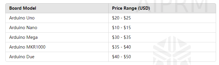
One of the most attractive features of Arduino is its low cost. Basic Arduino boards, such as the Arduino Uno, can be purchased for around $20. More advanced boards, like the Arduino Mega, may cost slightly more, but they still remain affordable compared to other microcontroller platforms.
Breakdown of Arduino Board Prices
![]()
These prices can vary based on the retailer and any additional components included in the purchase.
Related Read: Raspberry Pi Pico Price
Comparing Arduino to Other Platforms
Cost Comparison
When compared to other microcontroller platforms, Arduino often comes out on top in terms of affordability. For example:
- Raspberry Pi: Prices range from $35 for the basic model to $75 for more advanced models.
- BeagleBone Black: Typically costs around $55.
- STM32 Nucleo: Prices can range from $15 to $50, depending on the model.
Value Comparison
While Arduino is cheaper, it also offers a great balance of simplicity and functionality. Other platforms may offer more power or specific features, but they often come with a steeper learning curve or higher price tag.
Value Proposition of Arduino
Educational Value
Arduino is not just a tool for building projects; it's also an educational resource. Schools and universities worldwide use Arduino to teach electronics, programming, and engineering concepts. The hands-on experience provided by Arduino helps students grasp theoretical knowledge in a practical way.
Community and Support
The Arduino community is vast and incredibly supportive. Online forums, tutorials, and project repositories provide a wealth of information for both beginners and experienced users. This community support can be invaluable when troubleshooting issues or seeking inspiration for new projects.
Project Versatility
From simple LED blinkers to complex home automation systems, Arduino can handle a wide range of projects. Its versatility is one of its greatest strengths, making it a favorite among hobbyists and professionals alike.
Long-Term Cost Efficiency
Durability and Longevity
Arduino boards are known for their durability. With proper care, they can last for years, making them a cost-effective choice in the long run. Additionally, many projects can be built using a single Arduino board, reducing the need for multiple purchases.
Upgrade and Expansion
Arduino’s open-source nature allows for easy upgrades and expansions. New sensors, shields, and modules can be added without requiring a complete system overhaul. This modularity ensures that your initial investment continues to provide value as your projects evolve.
Hidden Costs
While Arduino itself is inexpensive, there are hidden costs to consider:
- Accessories and Components: Sensors, actuators, and other components can add up.
- Prototyping Tools: Breadboards, wires, and other prototyping tools may be needed.
- Time Investment: Learning to use Arduino effectively requires time and effort.
Case Studies: Cost vs. Value...
Read more -
Overcurrent Protection with LSF0108PWR
05/09/2024 at 06:36 • 0 commentsOvercurrent protection is a critical aspect of electronic circuit design, ensuring that components are not damaged by excessive current. The LSF0108PWR is a versatile overcurrent protection IC that offers a range of features to safeguard electronic devices. In this article, we will explore the role of overcurrent protection in electronic circuits and how the LSF0108PWR can be used to enhance circuit reliability.
Introduction
Overcurrent protection is essential in electronic circuits to prevent damage to components and ensure the safe operation of devices. The LSF0108PWR is a highly efficient overcurrent protection IC that can help enhance the reliability of electronic systems.
Understanding Overcurrent Protection
Overcurrent protection is a technique used to limit the amount of current flowing through a circuit to protect components from damage. It is achieved using various methods, including fuses, circuit breakers, and overcurrent protection ICs like the LSF0108PWR.
The Role of LSF0108PWR in Overcurrent Protection
The LSF0108PWR is a high-performance overcurrent protection IC that offers precise current limiting and fast response times. It can protect sensitive electronic components from damage due to overcurrent conditions, ensuring the reliable operation of electronic devices.
Benefits of Using LSF0108PWR
- Precision Current Limiting: The LSF0108PWR offers precise current limiting, ensuring that only the specified amount of current flows through the circuit.
- Fast Response Times: This IC has fast response times, reacting quickly to overcurrent conditions to protect components.
- Compact Size: The LSF0108PWR is available in a compact package, making it suitable for use in space-constrained applications.
Applications of LSF0108PWR
The LSF0108PWR can be used in a variety of applications, including:
- Power supply protection
- Motor control
- LED lighting
- Battery management systems
Design Considerations for LSF0108PWR
When using the LSF0108PWR in a circuit, it is essential to consider factors such as:
- Operating voltage and current requirements
- Thermal management
- PCB layout considerations
Conclusion
The LSF0108PWR is a versatile and reliable overcurrent protection IC that can help enhance the reliability of electronic circuits. Its precision current limiting and fast response times make it an ideal choice for protecting sensitive components from damage due to overcurrent conditions.
-
Step-by-Step Installation Guide for TLF35584QVVS1
04/10/2024 at 09:55 • 0 commentsAre you looking to install TLF35584QVVS1 but unsure where to start? This step-by-step installation guide will walk you through the process, ensuring a smooth and successful installation.
Introduction
TLF35584QVVS1 is a versatile electronic component used in various applications. This guide will help you install TLF35584QVVS1 with ease, whether you're a beginner or an experienced user.
Understanding TLF35584QVVS1
Before we begin, let's understand what TLF35584QVVS1 is. TLF35584QVVS1 is a multi-output power supply integrated circuit (IC) designed for automotive applications. It provides multiple regulated voltages, making it ideal for use in automotive electronic systems.
Tools and Materials Required
To install TLF35584QVVS1, you will need the following tools and materials:
- TLF35584QVVS1 IC
- Soldering iron and solder
- Desoldering pump or wick
- PCB (Printed Circuit Board)
- Power supply
- Multimeter
- Safety goggles and gloves
Installation Steps
- Prepare the PCB: Ensure the PCB is clean and free of any dust or debris. Place the TLF35584QVVS1 IC on the PCB in the correct orientation.
- Solder the IC: Use the soldering iron to solder the TLF35584QVVS1 IC to the PCB. Apply a small amount of solder to each pin while ensuring the IC remains flat on the PCB.
- Inspect the Connections: Once soldered, visually inspect the solder joints to ensure they are smooth and shiny. Use a multimeter to check for any short circuits or open circuits.
- Connect Power Supply: Connect the power supply to the PCB, ensuring the correct voltage and polarity. Use a multimeter to verify the output voltages from TLF35584QVVS1.
- Test the Circuit: Power on the circuit and test the functionality of TLF35584QVVS1. Check for proper voltage regulation and any abnormal heating.
Testing and Troubleshooting
If you encounter any issues during the installation or testing process, refer to the datasheet of TLF35584QVVS1 for troubleshooting tips. Common issues include incorrect soldering, faulty components, or incorrect wiring.
Conclusion
By following this step-by-step installation guide, you should be able to install TLF35584QVVS1 successfully. If you encounter any difficulties, don't hesitate to seek assistance from a qualified technician.
-
Decoding the 47k Ohm Resistor Color Code
12/26/2023 at 06:54 • 0 commentsResistors play a crucial role in electronic circuits, and their values are often represented by a color code system. Let's decode the color bands of a 47k ohm resistor to understand how this coding works and determine the resistor's value.
Overview of a 47k Ohm Resistor:
A 47k ohm resistor has a resistance value of 47,000 ohms, and the "k" indicates that the resistance is in thousands.
Color Bands on a 47k Resistor:
A 47k ohm resistor typically has four color bands. Let's interpret each band:
Color Bands:
- First Band (Digit 1): Yellow (4)
- Second Band (Digit 2): Violet (7)
- Third Band (Multiplier): Orange (10^3)
- Fourth Band (Tolerance): No Color (20%)
Decoding the Value:
Color Interpretation:
- The first band (Yellow) represents the digit 4.
- The second band (Violet) represents the digit 7.
- The third band (Orange) represents a multiplier of 10^3.
Calculating the Resistance:
- Combine the digits from the first and second bands: 47.
- Multiply this value by the multiplier from the third band (10^3): 47 * 10^3 = 47,000 ohms or 47k ohms.
Tolerance:
- The fourth band (No Color) indicates no specific tolerance color, defaulting to ±20%.
Representation in Ohms:
- The complete value of the 47k ohm resistor is expressed as 47,000 ohms.
Color Code Summary:
- First Band (Digit 1): Yellow (4)
- Second Band (Digit 2): Violet (7)
- Third Band (Multiplier): Orange (10^3)
- Fourth Band (Tolerance): No Color (20%)
Conclusion: Understanding the Color Code:
Decoding the color bands of a 47k ohm resistor involves associating each color with a numerical value and multiplier. In this case, Yellow represents 4, Violet represents 7, Orange represents a multiplier of 10^3, and the absence of color in the fourth band defaults to a tolerance of ±20%. By combining these elements, we arrive at the resistor's value of 47,000 ohms or 47k ohms. Understanding the color code system empowers engineers and hobbyists to quickly identify resistor values for effective circuit design.
-
CR123 vs. CR123A Batteries - A Cost Comparison
12/18/2023 at 07:02 • 0 commentsEver popped open a gadget – maybe a laser pointer, camera, or flashlight – and found yourself face-to-face with a tiny, mysterious battery labeled "CR123" or "CR123A"? Don't be fooled by their similar names and size; these little powerhouses have distinct personalities and price tags. Let's delve into the world of CR123 vs. CR123A batteries and help you choose the champion for your device.
Size Matters (But Not That Much)
At first glance, these batteries appear identical. Both boast a cylindrical shape, measuring 34.9mm tall and 17mm in diameter. However, a subtle difference emerges: CR123A batteries are ever so slightly thicker, clocking in at 3.2mm compared to the CR123's 3.0mm. This seemingly minor discrepancy can be crucial for tight spaces. Some gadgets, like specific camera models, might only accommodate the slimmer CR123, while others happily accept both variations.
CR123 battery and CR123A battery sidebysideCapacity Quandary: Who Reigns Supreme in Stamina?
This is where things get interesting. The CR123A packs a punch with a higher mAh (milliampere-hour) rating, typically offering around 225mAh compared to the CR123's 170mAh. This translates to potentially longer runtimes for your devices, making the CR123A the king of endurance for frequently used gadgets like remote controls or laser pointers.
Cost Crusaders: Who Wins the Wallet War?
Here's where the scales might tip. CR123 batteries are often slightly cheaper than their A counterparts, with the price difference varying depending on brand and quantity purchased. So, if you're powering low-drain devices like smoke detectors where runtime isn't a major concern, the CR123 might be a more budget-friendly option.
Bonus Round: Niche Players Enter the Arena!
While CR123 and CR123A are the main contenders, don't forget these niche players:
- CR1616: This even slimmer option (1.6mm) is perfect for ultra-compact devices like some health trackers.
- CR2016: Offering a capacity similar to the CR123 but in a thinner package, it's another space-saving champion.
Choosing Your Champion: The Verdict is Yours!
Ultimately, the perfect battery is a match made in device heaven. Consult your gadget's manual or manufacturer's recommendations to find the ideal power source.
Here's a quick cheat sheet to help you decide:
- Need a slim fit? The CR123 might be your knight in shining armor.
- Craving extended playtime? The CR123A will keep your devices humming longer.
- Cost a concern? CR123s might be enough for low-drain applications.
- Space constraints? Consider niche players like CR1616 or CR2016.
Remember, understanding the strengths and weaknesses of these miniature powerhouses empowers you to make informed choices and keep your devices happily operating. So, the next time you face the CR123 vs. CR123A conundrum, remember this blog and choose wisely!
Beyond the Blog: Keep the Conversation Flowing!
- Share your own battery wisdom: Have a favourite use for CR123 or CR123A? Share your tips and tricks in the comments below!
- Spread the knowledge: Share this blog on your social media or relevant online communities to empower others to choose the right battery for their needs.
- Explore the battery-verse: There's a whole world of batteries out there! Dive into other blog posts and resources to discover more about different types, brands, and their applications.
Together, we can demystify the world of batteries and ensure our devices keep humming happily, powered by the right tiny titans. Read more differences between CR123 and CR123A here.
-
Unlocking the Potential of the 7493 IC
08/31/2023 at 06:41 • 1 commentThe 7493 IC is a 4-bit binary counter integrated circuit, part of the larger 7400 series of digital logic chips. This IC is specially designed for counting applications and can be configured in various modes, including both ripple counter and synchronous counter functionalities.
Key Features of 7493 IC
- 4-bit Binary Counter: The chip can count in a binary sequence from 0 to 15 when all four bits are used.
- Multiple Counting Modes: The chip supports ripple and synchronous counting, giving you flexibility depending on your application's needs.
- Multiple Outputs: The IC offers outputs for each bit of its count (QA, QB, QC, and QD).
- Reset Functionality: It includes reset pins that instantly set the counter back to zero.
- Wide Operating Voltage: Usually, it operates between 4.75V and 5.25V, making it compatible with most low-to-moderate voltage applications.
Common Applications- Digital Clocks: The 7493 can be the counting mechanism for digital time-keeping devices.
- Frequency Counters: It's often used in devices that measure frequency, such as radio equipment.
- Dividing Frequencies: The IC is capable of frequency division, a useful feature in musical instruments and tuners.
- Industrial Counting Systems: In an industrial setting, it can count items on a conveyor belt or other types of product counting.
How It Works- Clock Input: The IC begins counting upward with each pulse at its clock input pin.
- Binary Output: The four output pins (QA, QB, QC, and QD) reflect the current state of the counter in binary form.
- Reset: The counter can be instantly reset to zero through the reset pins.
Tips for Using 7493 IC
- Consult the Datasheet: Always refer to the specific datasheet for the 7493 IC you use to understand its electrical characteristics and operational limitations.
- Selective Counting: Depending on your application, you may not need to use all four bits of the counter so that you can configure it accordingly.
In summary, the 7493 IC is a versatile and reliable component for any project that requires counting or frequency division. Its multiple features and wide applicability make it a handy tool for hobbyists and professionals. -
CD4017BE Pinout: Unraveling the Magic of a Classic Counter IC
08/17/2023 at 04:02 • 0 commentsThe world of electronics is brimming with components, each adding a distinct facet to the intricate puzzle of devices we use daily. One such component is the CD4017BE. While it might sound like just another alphanumeric jumble, its importance in digital circuits is profound. In this blog, we'll delve deep into understanding the pinout of the CD4017BE, helping you navigate its capabilities with ease.
A Glimpse at the CD4017BE
The CD4017BE is a decade counter/divider integrated circuit (IC) known for its versatility in the digital electronics arena. It is often used in LED chasers, light sequencers, and a myriad of other applications requiring sequential operations.The Essence: CD4017BE Pinout
Understanding the pinout of any IC is pivotal for its appropriate application. The CD4017BE has a total of 16 pins. Here's a simplified guide:- Vss (Pin 8) and Vdd (Pin 16): These pins connect the IC to the power supply. Typically, Vss is connected to the ground, while Vdd is connected to the positive voltage.
- Clock Input (Pin 14): This pin is where the CD4017BE receives the clock signals. Each pulse advances the counter.
- Clock Enable (Pin 13): It enables or disables the clock. If high, the clock is disabled.
- Reset (Pin 15): When high, this pin resets the counter to zero.
- Output Pins (Q0 - Q9): These are the outputs (Pins 1, 2, 3, 4, 5, 6, 7, 9, 10, and 11). For a decade counter like CD4017BE, ten represent each count from 0 to 9.
- Carry-Out (Pin 12): This pin goes high when the counter moves from the ninth to the zero count, which is useful for cascading multiple CD4017BE ICs.
Practical Applications
The CD4017BE is versatile, thanks to its distinct pinout:- LED Sequencers: You can create beautiful sequential lighting effects by connecting LEDs to their output pins.
- Dividing Frequency: In combination with timers, the CD4017BE can divide frequency, generating output signals at a fraction of the input clock frequency.
- Binary Counting: With its 10 outputs, the IC can be employed in binary counting applications, making it a fit for educational projects.
Final Thoughts
The CD4017BE, with its specific pinout and functionality, stands tall in the world of digital ICs. It is a classic, reminding us that simplicity and versatility can sometimes lead to brilliance. Understanding the CD4017BE pinout can open the door to numerous inventive applications for enthusiasts and professionals.
-
The Power of the 8-Bit Counter IC: Delving Deep into Digital Counting
08/15/2023 at 08:13 • 0 commentsIn the wide world of electronics, the unsung heroes are often the integrated circuits (ICs) that play a monumental role in shaping the performance of a device. Among the myriad of ICs available in the market, the 8-bit counter IC is a notable standout, frequently appearing in numerous digital applications. Let's embark on a journey to understand this gem in electronics.
Introduction to 8-Bit Counter IC
An 8-bit counter IC, as the name suggests, is designed to count sequences in 8-bit binary formats. Essentially, it can count from 0 (represented as 00000000 in binary) up to 255 (11111111 in binary). Such ICs are fundamental in digital systems, especially where precise counting or sequencing is paramount.
Why 8-Bits?
Bits are the fundamental units of digital information. An 8-bit system essentially provides 2^8 (or 256) distinct combinations. This range is ample for many applications, from basic data storage to operations in devices like microcontrollers and computer processors.
Popular 8-Bit Counter ICs
There are several popular 8-bit counter ICs in the market:
- 74HC590: An 8-bit binary counter with a storage register and 3-state outputs.
- SN74LS593N: A versatile 8-bit binary counter with inputs tailored for various modes of operation.
- CD4040: Though it’s a 12-bit binary counter, the first 8-bits are often used in various applications, making it adaptable.
Key Features
- Parallel and Serial Outputs: Many 8-bit counter ICs offer parallel and serial outputs, facilitating easier interfacing with other components.
- Reset Function: This allows the counter to revert to its initial state, offering flexibility in operations.
- Clock Inputs: Determines the counting rate, with some ICs equipped with up and down clock inputs.
Applications of 8-Bit Counter ICs
- Digital Clocks: Keep track of seconds, minutes, or even hours.
- Frequency Counters: To measure the frequency of signals.
- Analog-to-Digital Converters: Acting as an integral part of ADCs, counting the digital pulses corresponding to analog signals.
- Digital Systems: For sequence generation or simple data storage.
Given their binary nature, 8-bit counter ICs can be easily integrated with other digital systems. Whether interfacing with a microcontroller for a DIY project or embedding within a more complex electronic setup, their adaptability is one of their strongest suits.
Final Thoughts
The 8-bit counter IC is not just a component; it's a testament to the power of digital electronics. While 8-bits might seem simple, their range of applications and functionalities is remarkable. As technology continues to evolve, the significance of such foundational components only magnifies.
Next time you're embarking on a digital project, remember the might of the 8-bit counter IC, find it on jotrin, and harness its power to make your venture a resounding success!
-
Exploring the CD4017 Decade Counter
08/10/2023 at 09:59 • 0 commentsCD4017, a 16-pin CMOS decade counter/divider, is a component of the LV-A logic family and falls within the 74LV series. It takes a clock signal from its input and sequentially activates the 10 outputs each time a clock pulse is received. This versatile IC, CD4017, finds extensive application in projects such as Light Chasers and Matrix Dies. It also serves various functions, including binary counter/decoder, frequency division, divide-by-N counting, and alarm systems.
To comprehend the operation of IC CD4017, a grasp of its pins is essential:
![]()
Input Pins:
a. Reset (Pin 15) – This pin resets the counter to zero. Connecting the fourth output to pin 15, the counter counts up to the third output and restarts from zero.b. Clock (Pin 14) – The output is triggered when Pin 14 goes high. For the first clock pulse, pin 3 produces the output; for the subsequent pulses, pin 2, and so on. After ten pulses, it cycles back to the Q0 output.
c. Clock Inhibit (Pin 13) – This pin switches the counter "on" and "off." When pin 13 is high, the counter ignores clock pulses, preventing advancement. In this setup, pin 13 is grounded.
Output Pins (Pin Q0-Q9) – Sequential output reception, starting from pin 3.
Ground (Pin 8) and Supply (Pin 16) – Provide power and ground for the IC.
Carry Out (Pin 12) – Links multiple CD4017 ICs. In the circuit, this pin remains unconnected as only one IC is used.
Circuit Operation:
The counter initiates from zero upon pressing the switch, incrementing with each positive pulse at pin 14. The LEDs illuminate in sequence: LED2 for the first switch press, LED1 for the second, and so forth. Once LED4 illuminates, pressing the switch will not activate any LED as the counter counts to Q9 and resets (via a connection from pin 11 to pin 15).
Resetting the counter to zero upon circuit activation is achieved through C2 and R3, which toggle pin 15 high and low. A diode between pins 11 and 15 ensures the counter restarts by making pin 11 low and pin 15 high.
To counteract contact bounce that might generate multiple pulses, C3 and R4 introduce a short delay. This keeps pin 14 high until the switch is pressed again.
CD4017 Circuit Diagram
![]()
Project Components
- Capacitor
- Diode 1N4001
- LED
- Resistor
For more project details, check here.
-
Demystifying the Inner Workings of Counter ICs
08/07/2023 at 09:45 • 0 commentsCounter ICs (Integrated Circuits ) are pivotal in applications requiring accurate counting, timing, and event sequencing in digital electronics. These unassuming chips can count pulses or events and produce an output based on the counted value. In this article, we will delve into the inner workings of Counter ICs, shedding light on their functionality, operation, and the magic that makes them tick.
![]()
Counting Mechanism
At the heart of a Counter IC lies a series of flip-flops, bistable multivibrators capable of storing binary information. Each flip-flop represents a binary digit, and when connected in a cascading fashion, they form a counter that can count from 0 to its maximum value based on the number of flip-flops used.Clock Input
Counter ICs operate in synchronization with an external clock signal. This clock input determines the rate at which the counter increments or decrements its value. The rising or falling edge of the clock signal triggers the flip-flops to transition between their binary states, resulting in the counting action.Up and Down Counting
Counter ICs can count both upwards and downwards, depending on their configuration. The value increases with each clock pulse in an up-counter, while in a down-counter, the value decreases. Based on the input signal, Bidirectional counters can perform up-and-down counting.Output Generation
The output of a Counter IC is represented in binary form and is available at the individual outputs of the flip-flops. For example, a 4-bit binary counter will have four output pins, each representing a binary digit. These outputs can be used for various purposes, such as driving displays, triggering other components, or providing input to other logic circuits.Decoding Logic
Some Counter ICs include integrated decoding logic, which simplifies the process of using the counter's output. Decoding logic translates the binary count into a specific format or sequence, making it easier to display the count value on digital displays or trigger specific actions when certain count values are reached.Applications in Context
To understand how Counter ICs work, it's crucial to explore their applications:Digital Clocks: In a digital clock, Counter ICs keep track of the number of clock pulses and convert them into hours, minutes, and seconds.
Frequency Division: Counter ICs divide input frequencies to generate lower output frequencies, which is essential in communication systems and frequency synthesizers.
Event Counting: In industrial automation, Counter ICs monitor events, such as the number of products produced on an assembly line or the rotations of a motor.
Pulse Generation: Counter ICs generate precise pulse sequences for tasks like triggering electronic switches or controlling stepper motors.
Conclusion
Counter ICs may seem like small chips, but they wield immense power in digital electronics. These chips perform the remarkable task of counting and sequencing events with precision and accuracy through flip-flops, clock signals, and clever circuitry. Whether driving digital clocks or enabling advanced automation systems, Counter ICs continue to shape how we interact with technology. To dive even deeper into the workings of Counter ICs, explore the comprehensive guide available, which unveils the intricate mechanisms behind their functionalities. Counter ICs will undoubtedly remain at the forefront of innovation as technology advances, enhancing the efficiency and accuracy of countless electronic applications.