-
CoreXY Mechanism
04/25/2021 at 14:35 • 0 commentsCoreXY Mechanism

CoreXY Mechanism CoreXY Kinematics
The corexy parallel kinematics mean's that the motors are the largest source of inertia within the system, and are stationary. This means rapid acceleration because the two stepper motors provide a means of moving both axes independently or simultaneously. The major benefit of the design is that the motors remain in a static position.
The corexy kinematics is a complex motion system where X or Y motors move together or opposite of each other to move the carriage from left to right or towards or away . If you were to move just one motor you would see the print head move diagonal.. If the two motors move opposite of each other the print head will move along the X-axis, If the two motors move in the same direction the carriage will move along the Y-axis.
Belt Path
A printer’s motors can be offset at different heights so that the belt routing runs a straight belt path and doesn't have to be twisted. But this belt routing path would also mean that on one side of the gantry the belt would have the teeth on the side of the idler wheel which wouldn’t run as smooth and could lead to artifacts within printed parts.
Motor Movement
- Both Motors Move Clockwise >> Carriage Moves Left
- Both Motors Move Counter Clockwise>> Carriage Moves Right
- Both Motors Move Opposite of Each Other>> Carriage Moves Toward & Away
- One Motor Moves>> Carriage Moves Diagonal
Also See:
-
CoreXY Motor Mounts
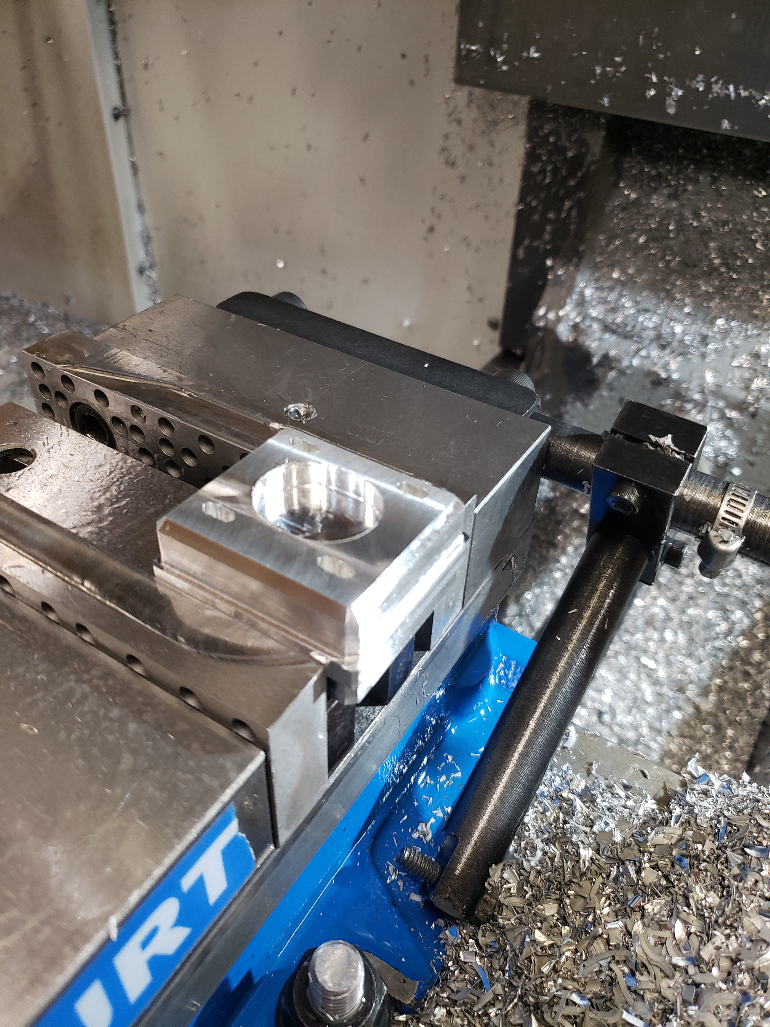
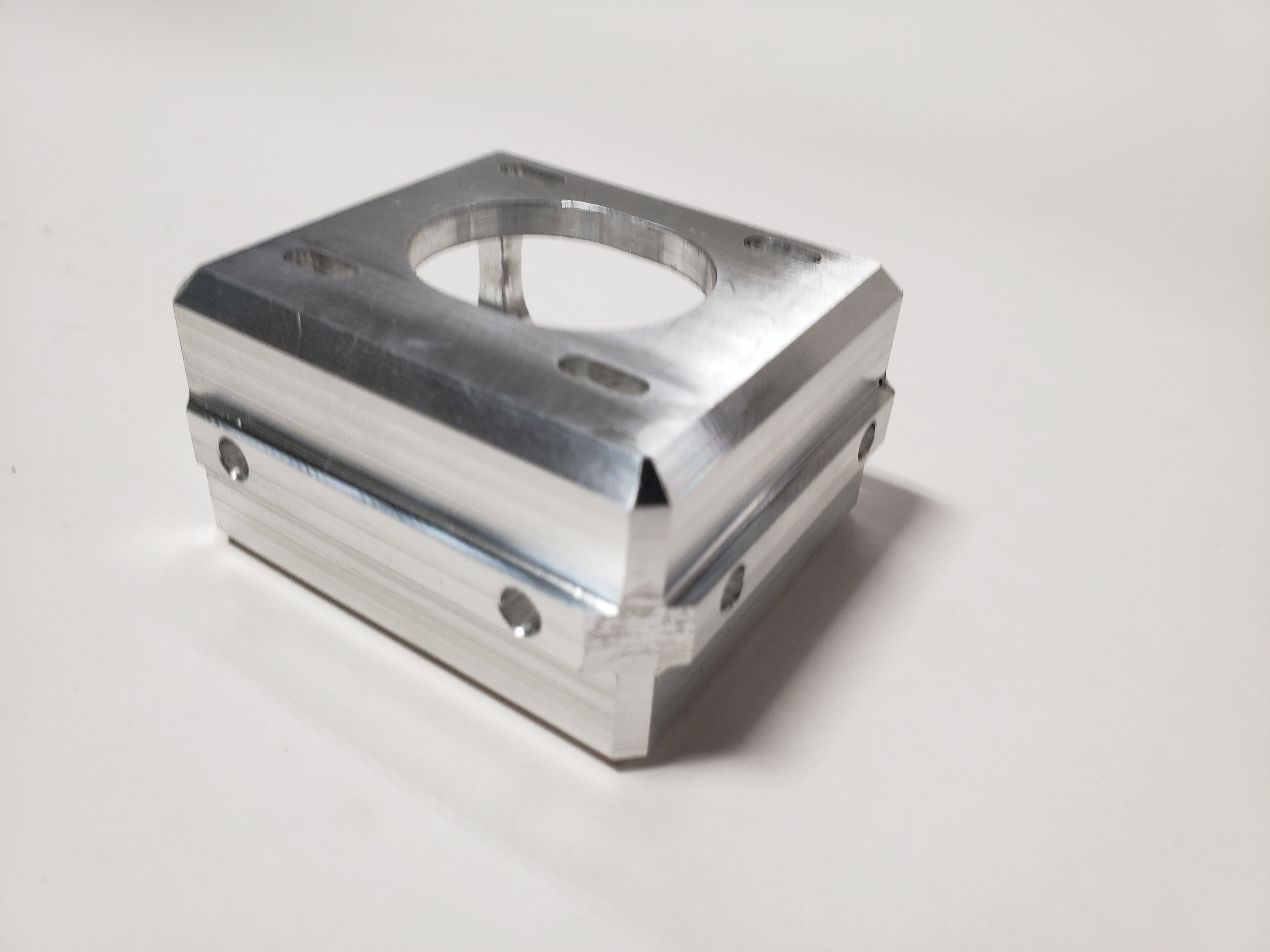
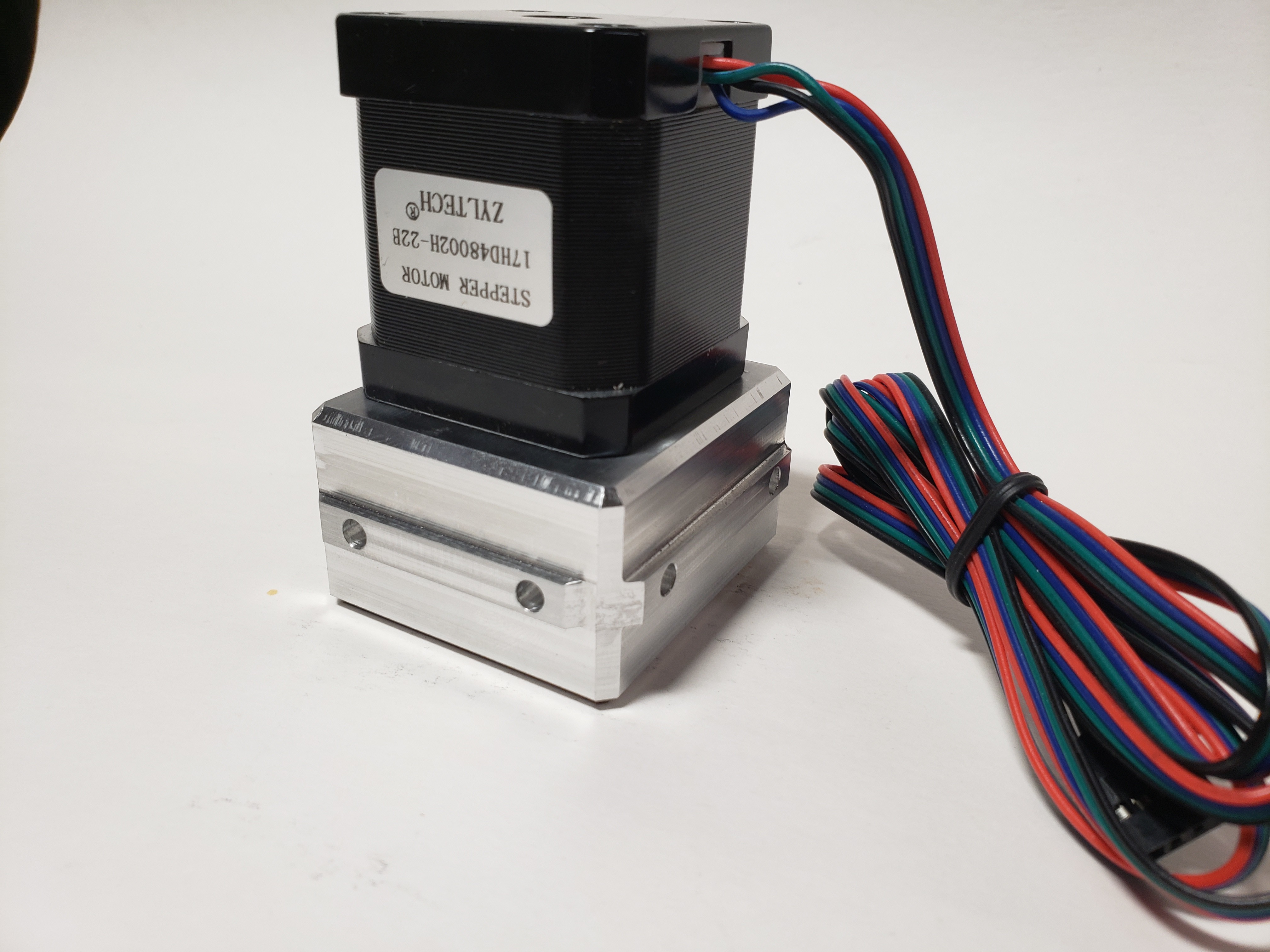
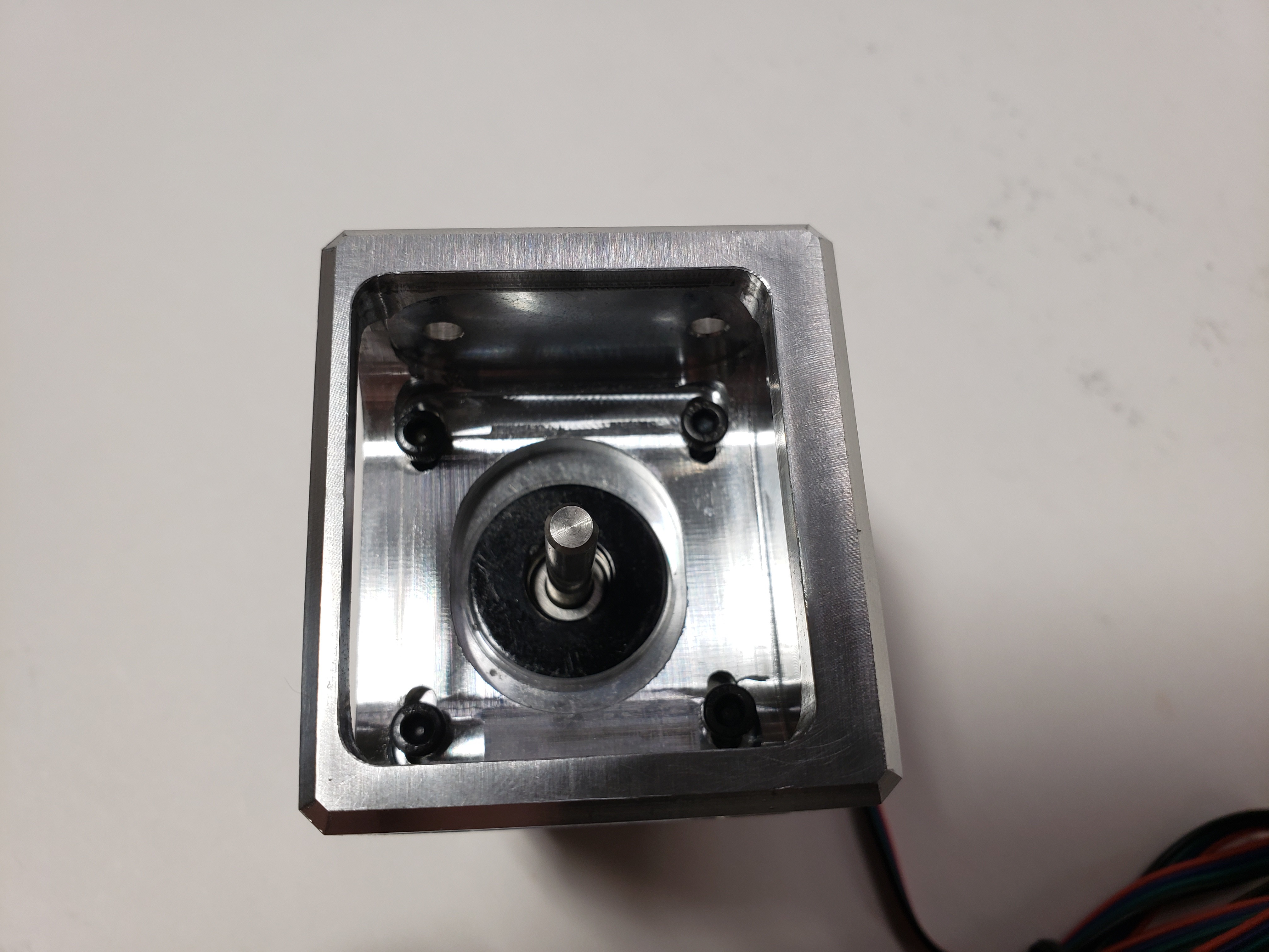
03/24/2021 at 02:14 • 0 commentsI've been working on a modular and scalable corexy design called the SolidCore for over a year now. The plan is to have a platform or ecosystem of parts that can be used on any 3d printer that uses 2020 frame extrusion. The original motor plate had a 20mm cut out to seat in the corner of the frame. One of the problems I ran into was that many of the frames use square corner brackets that don't have the clearance needed in order to mount the motor plate mount. So I'm designing a motor mount that mounts within the inside of the frame instead of on top of the frame.
![]()
![]()
Before
![]()
The old SolidCore motor and idler mounts worked great but limited the number of frame extrusion bracket options.
![]()
![]()
Many of the new frame brackets or connectors use an endcap style connector.
After
![]()
![]()
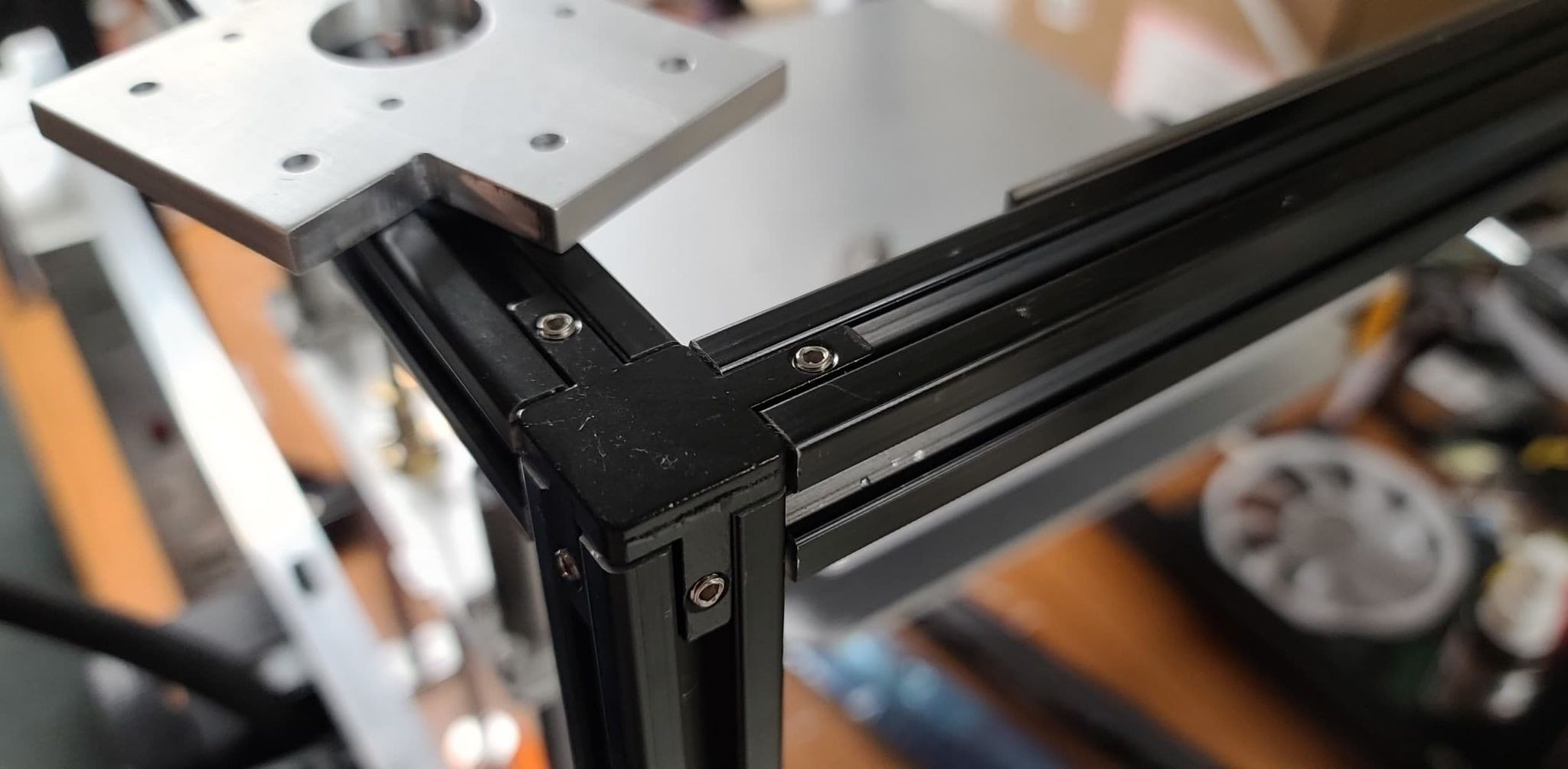
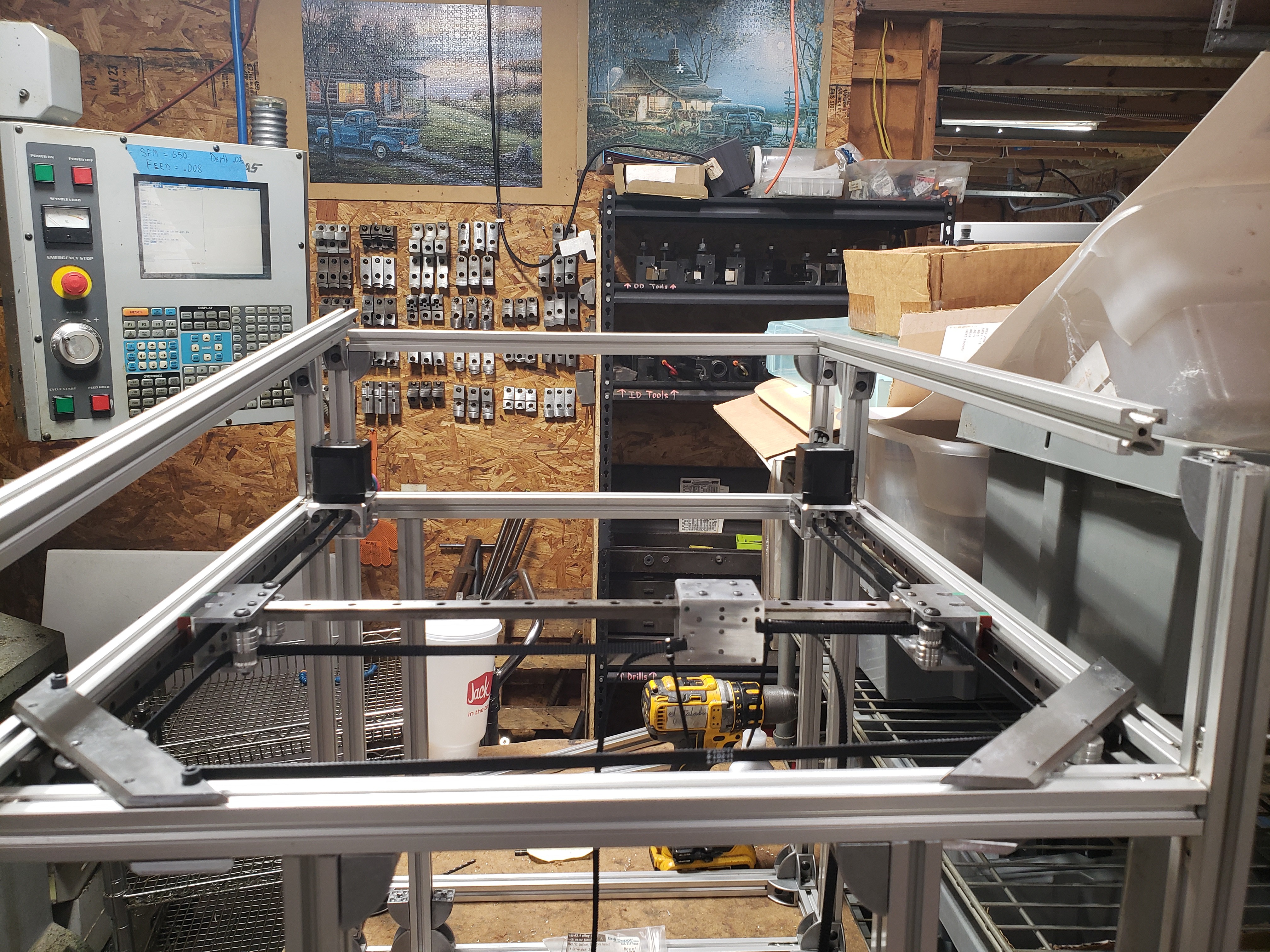
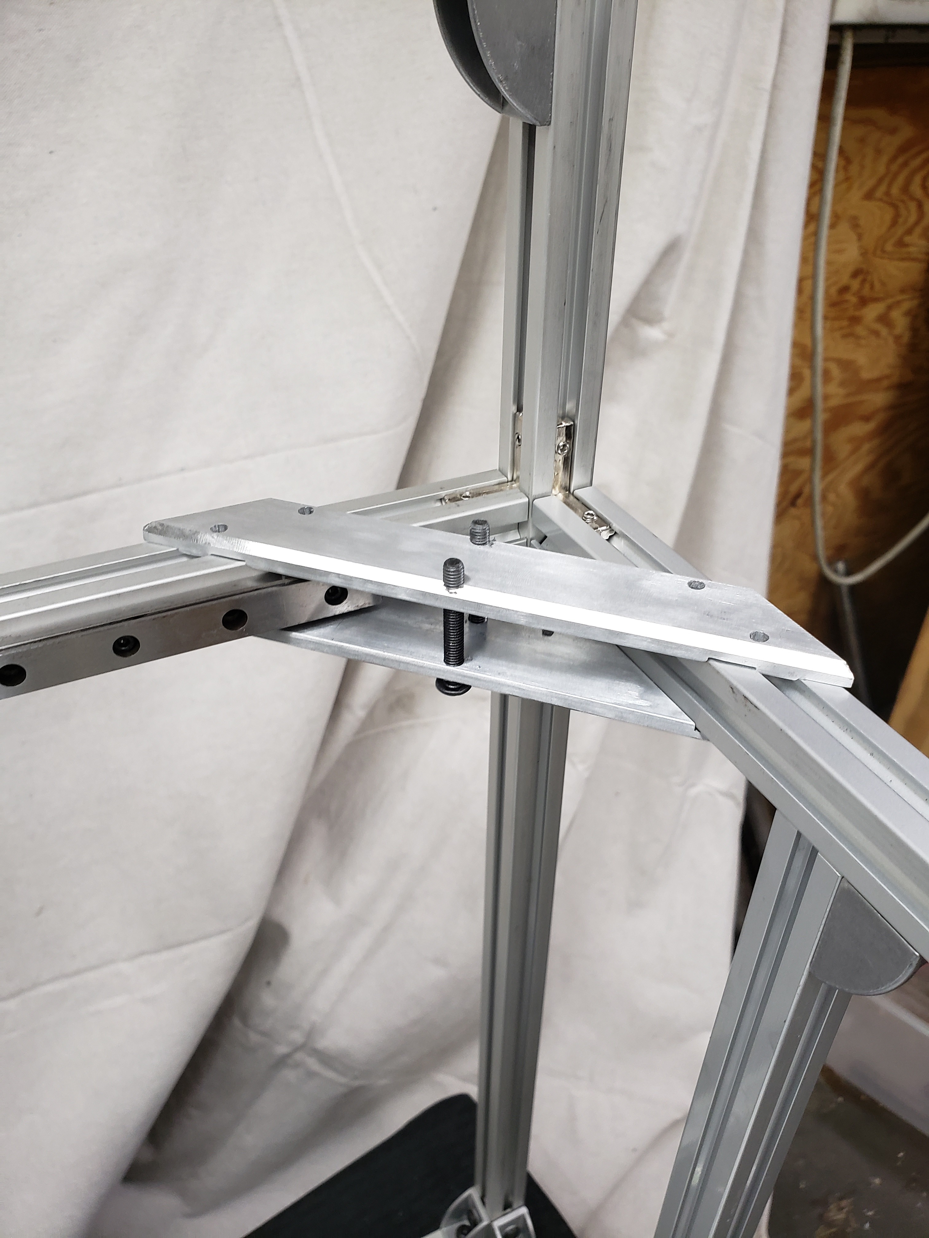
Frame Rigidity
![]()
I was planning on scaling up to a 3030 mm frame extrusion on the next larger corexy build. With the components mounting within the frame adds more rigidity to the frame.
![]()
![]()
![]()
![]()
![]()
Download 3D Model
-
CoreXY Belt Path: Crossed Belts vs Stacked Belts
02/19/2021 at 00:45 • 0 commentsCoreXY Belt Path
![]()
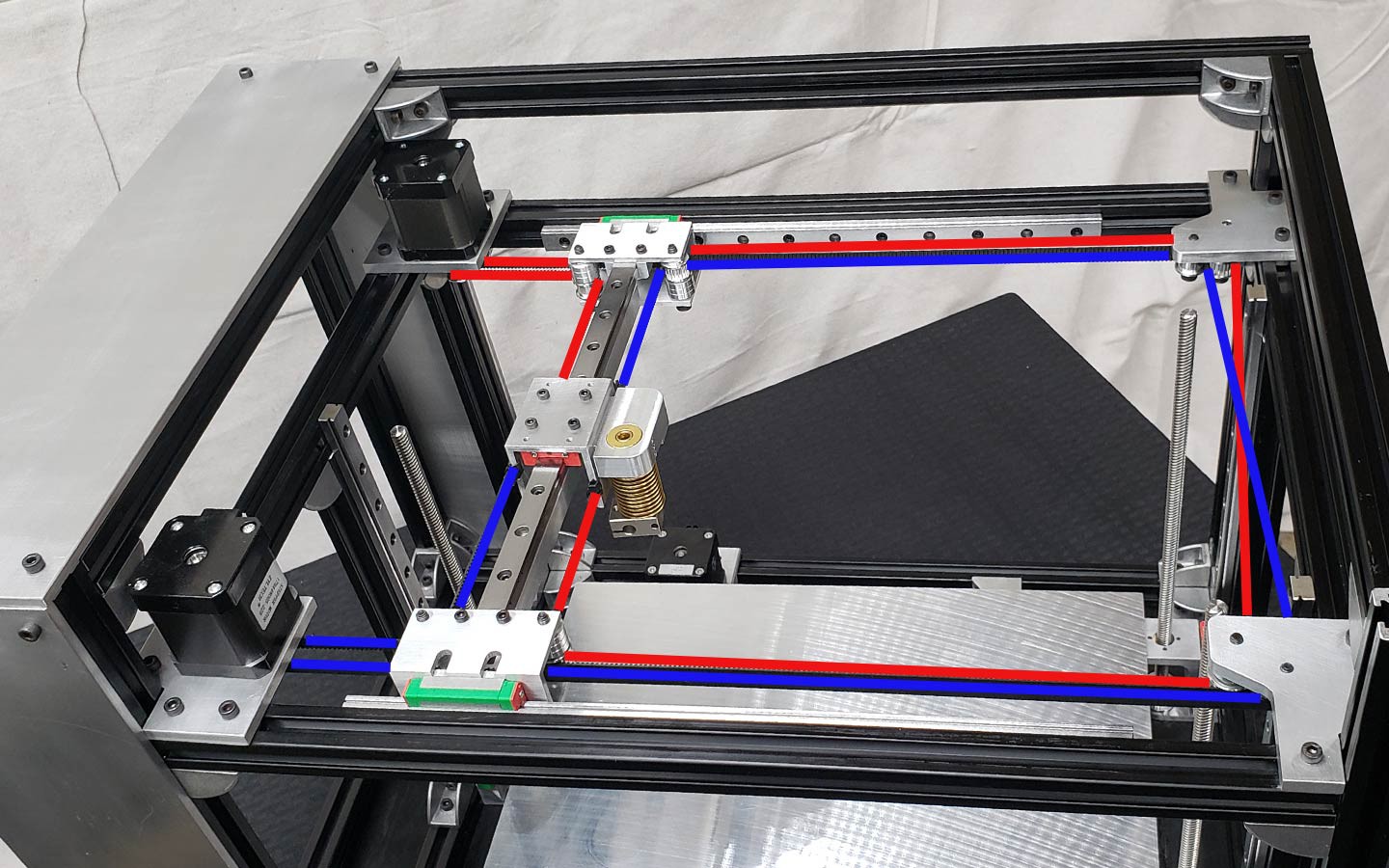
CoreXY Diagram
Belt Path Crossing
While the SolidCore 3D Printer design had a lot of influence from the Railcore's design, which also has the "x" shape belt path that some say “serves no purpose.” True, but you see the quality prints that the Railcore community is putting out. The print quality of the RailCore is AMAZING! Although the belts don't have to cross if the pulleys are at different z-levels. I originally thought that the difference between the hbot core xy design was that the corexy belts crossing segment.
We already designed and built the SolidCore with the crossed belt path so we're going to stick with it for now. Later on after many performance tests I'll try out some other design configurations to test out any changes.
Hbot vs CoreXY
The difference between hbot and corexy is that hbot has a single belt on a single plane, corexy can have either two non-intersecting planes or a single plane with pulley idlers on different levels which keeps the belts from rubbing.
While the Hypercube has the stacked belts on different planes configuration unlike the SolidCore corexy configuration "x" crossed belts.
Stacked Pulleys
Offsetting the stepper motors with stacked belt path pulleys may give the belts a clean run and simplify belt alignment. A printer's motors can be offset at different heights so that the belt routing runs a straight belt path and don't have to be twisted. But this belt routing path would also mean that on one side of the gantry the belt would have the teeth on the side of the idler wheel which wouldn't run as smooth and could lead to artifacts within printed parts.
SolidCore and RailCore Crossing Belt Segments
![]()
While many frown upon the crossed belts configuration found on the Railcore or SolidCore due to the y-axis could possibly bind if the y-axis isn't completely perpendicular to each other.
Linear Rail: Supported vs Unsupported
I'm using a crossbar made from u-shaped aluminum extrusion. Depending on the rail length if the y-axis has an unsupported linear rail it could possibly lead to deflection. The load of the belt paths have to be balanced along the running plane with the pulleys. An unbalanced load can lead to the belts trying to slip off the pulleys and premature wear of the bearings.
-
CoreXY 3D Printer
05/01/2020 at 07:41 • 0 comments
SolidCore Printer - The whole idea is to build a corexy printer that has:
- Modular
- Scalable
- Linear Rails
- BOM utilizes standard and available printer parts people already have so they can convert their printer into a SolidCore
- Easily add an enclosure
- All metal components or printable
We’ll probably make some changes such as reorienting the the y-axis linear rail into a vertical position similar to the RailCore, redesigning the carriages and motor/belt mounting plates where the z-axis motors are placed on the bottom of the machine. When I first designed the plates I thought it would look cool with the motors on top but after I machined everything I realized that moving the bed up and down could cause deflection in the main plates. I’m also considering making the carriage components and rail support one piece similar to the latest update on E3D’s Tool Changing printer. We’re working on a small budget lol which “recycling” parts from previous builds. For example the bed is made from 3/8 inch thick aluminum that we robbed from an old printer. We’ll change that to 1/4 inch thick once we get more money. The left motor plates are going to be re-machined to give room for a tool changer setup. The overall footprint of the machine relative to print volume is somewhat excessive. In order to have a solid enclosure design I had to move the motors inside the frame boundary. This sacrificed the overall printer size to print volume ratio.
DIY Designs
After searching the internet and studying every machine design that I could possibly find i begin to take note of the pros and cons of each motion system or platform. Some had great communities that further developed the machine. Some of the printers I researched were:
HyperCube Evolution or HEVO
C-bot / D-Bot
Jubilee
Hevort
Railcore
E3D Toolchanger
BlackBox
Mike Fisher’s QuadRod
Maarten van Lier’s corexy build
Triple Independent Motors Z Axis
We’re planning to use 3 z-axis stepper motors on the SolidCore printer. Each lead screw will be constrained by a MGN12 linear rail. Originally we were working on a design that used one single z-axis motor and a belt routing the three lead screws together in sync. But after having trouble sourcing the belt that was the perfect length I decided to just go with three stepper motors similar to the HeVort printer or Jubilee tool changing corexy.
I'll update the files when finished but there’s still a lot of work to be done.