-
EPROM2764 - Hacked
12/06/2023 at 09:33 • 5 commentsProgramming 2764 EPROM with a Mega2560, SD card reader and 5-12V Buck converter
If you have ever wondered what it would be like to have a real retro -computer-nerd experience, then maybe programming EPROMs will fit the bill for you. Since the late 60's there were many and varied EPROMs sold, with different specs, but had better and easier programming procedures as time went on. Many had mysterious 3 lots of power rails early on (+5V, -5V and +12V), and with even more arcane requirements for Burning. The other factor was various manufacturers required different voltages on different pins and different timings for the same size memories. (Why "Burning"? Because many early EPROMs required 21V or 25V as a programming voltage, and it also had a great mental image of applying this voltage to a precious chip and BURNING the bits in, exciting!!! And conveyed the risk of what would happen if we got it wrong!!!).
When I wanted to add an 8kb EPROM to my SYM-1 project I was not optimistic this would be easy. However, boldly going where no other hackers had gone before me, I struck out to simplify things and make it possible to do some EPROM programming with minimal new purchases. I found out all one needed was a Mega 2560, a 28pin Socket (preferably ZIF, but not essential), a Mega 2560 shield, an SD card adapter, 5-12V buck converter (or some other static 12V power supply), and a single throw double pole switch. Some LED indicators can be added for the nervous Hackers who like to test things and feel comfortable things are happening properly. Essentially (and amazingly) things that can be found in the average spare parts (reuse?) bin these days.
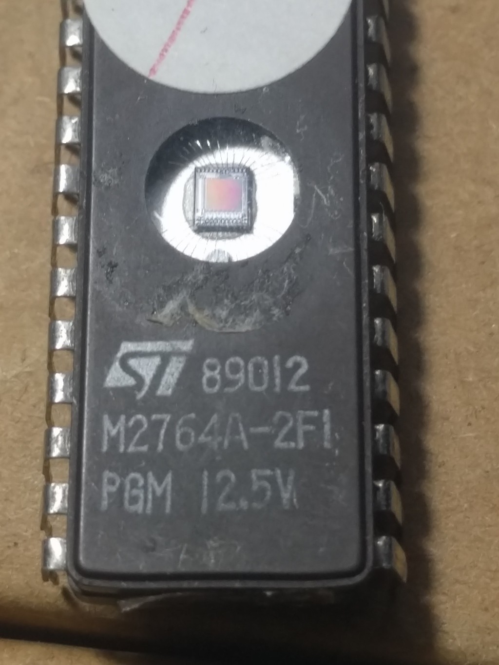
Below is the type of 2764 I have found has worked. Now, a warning, these things are produced in batches and I may have just been extremely lucky and found this system works on the only one or two chips in the known universe. However I have ordered from three different sources and they all work, so I feel confident some people will experience some success, in fact most people will experience total success. The EPROMs I have programmed 2 years ago are still working fine and have no errors. If you do not need 8Kb, then tie a few address lines low and just use part of it (they are so cheap, who cares?). You get the convenience of low cost Hacking, and a workable solution.
**** Download the EPROM Burning Program ****
![]()
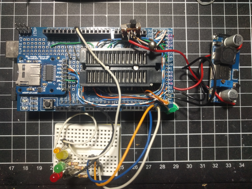
And the physical setup looks like this with the Mega 2560 below, shield on top with 28Pin ZIF socket, 5-12.5V buck converter (adjustable to 12.5V) and a single throw double contact switch (plus a few optional indicators LEDs).
![]()
The wiring gets a bit messy on the shield board, but can be done. If you want to use one of the shields with a prototyping board (see the one above where I have added the indicator LEDs, it came with the Mega2560 prototyping shield. Search eBay with "Arduino Mega 2560 Prototype PCB Shield with LEDs Reset Switch + Mini Breadboard") then the pins can be connected (note a double width dual in line socket would need to be added to the RHS board of the shield to facilitate the plugin wires) with the usual prototyping "plug and play" connectors. The big advantage of this idea is that many ROMs/EPROMS and even EEPROMs could be accommodated by moving the wires around and writing your own software building/improving on my work.
Looking at the connections I found to work to Burn the 8kb EPROMs, so we are are looking to Burn 2764's
   Port  MegaPin Vpp   1         28 Vcc      Port Mega PIN
    K    12      A12   2         27 !PGM     K     15
    A    29      A7    3         26 NC       Vcc
    A    28      A6    4     ...
Read more -
Extensions to SYM-1 Monitor: Saving and Loading, S3 and L3
03/05/2022 at 10:18 • 0 commentsThe Sym-1 SBC was at the cutting edge of the growth of the 8-bit micro computer. It had very good expansion capabilities for I/O but initially relied heavily on the Cassette Recorder as the medium for saving and loading programs. When programs were in the order of 10 of thousands of bytes long this was a practical, and very economical solution of the day (C:1975-1980). However cassette tapes were not particularly reliable or fast. Worst of all they required considerable organisation to be finding and playing back the right tape for the right program.
The common experience of having a Disk Filing System was probably about 5-10 years off when the Sym-1 hit the shops C;1978. One of the more robust parts of its design was a comprehensive Monitor (Mon1.1) program that allowed the user to manually enter and edit programs in Hex format. It also allowed for 8kB language ROMs, such as Microsoft Basic and the Resident Assembler and Editor (RAE) to be onboard and in ROM. For many users to switch the computer on and have these major packages instantly available were game changers. These packages also very efficiently made extensive use of the subroutines built into the monitor program. The Sym-1 used a pressure-pad hexadecimal keyboard and 7-segment digital display. However a terminal could be hooked up to the board as well and which ever input, hex keyboard or TTY, was detected as active first, it took over the interactions with the user. This required the hexadecimal keyboard to generate standard ASCII tokens for commands and data, so this made swapping to a full ASCII keyboard and display just a matter of changing a few vectors on initialisation. It also meant it was seamless to have full ASCII interaction with BASIC and RAE as well.
One of the features that built into the monitor is vectoring of "unrecognised command" errors that are generated when undefined commands are entered. The monitor passes control through a vector before reporting them to the user. If the vector is taken over, unrecognised commands can be diverted to create new commands that have the same style, format and structure as the existing commands. The extensions then look and feel like they were always in the design. The commands to save and load data have S1 (Kim format) and S2 (SYM-1 high speed format) and using the latter as an example worked like this:
.S2 xxxx,aaaa,bbbb where xxxx was the index number of the program, aaaa and bbbb was the start address and end address respectively of a block of code to be saved. Notably this meta data was also saved as part of the tape data structure.
.L2 xxxx allowed the program with the index number xxxx to be loaded automatically back to its original address.
.L2 xxxx,aaaa allowed the loading/starting point in memory to be chosen.
xxxx can be any four hexadecimal digits. So ASCII style names can be used eg 8kB Microsoft BASIC might be saved and loaded as BA51 ie BASI and CE55 could be CHESS( se below)
This was a natural extension to the Mega Filing System, so the S3/L3 commands were created. It meant binary chunks of memory contents could be saved as files and reloaded to the original address or a new address. To do this the first two bytes of all saved files contain the default 16bit address they were saved from, and in many cases, most likely to be reloaded back to that address. This means a saved file will always be seen by the Mega 2560 as two bytes bigger than the memory block used to create it. Why do this? Well a long term goal is to be able create a library function where unknown commands are also looked up as files and can be executed by simply typing their filename. The program would be loaded at the default address, and execution begun at the start of the file. This would allow extension of commands and memory re-use (eg sequences of programs could be run in the same memory space, others might be semi permanent etc). A related goal was have all filing transactions run in raw binary and not have...
Read more -
SYM-1 to USB Serial
01/30/2022 at 02:50 • 2 commentsThe Sym-1 was created by Synertek in the age of Teletypes ASR-33 when they were pretty much the best "golden standard" interface available for some, and for others the cheapest was the ubiquitous Hex keyboard and display. Well it was 1978, or thereabouts, and real live hardware of any sort was hard to come by, and these guys wanted to reach out to what we would call "startups" everywhere to try and hopefully buy this exciting new technology. These were the Arduinos of the 1970-80s. Many big players like Apple, Commodore and Acorn got involved and sold many thousands (millions?) of computers based on the 6502 processor. But it also opened a fantastic world to a whole bunch of bedroom enthusiasts who just wanted to know what was going on and what these things could do. The board that preceded the Sym-1 (originally called the VIM-1), was the KIM-1 designed by Mostek. This was a huge success, and was loved by enthusiasts (no such terms as nerds, geeks or hackers back then) the world over The Synertek design was an upgraded model and a much more capable machine, though the underlying technology was the same.
CRT's (Cathode Ray Terminals) at that stage were only glimpsed through the closed doors of the main terminal rooms of a card punch room that the lowest rung research students got to batch process their wonderful creations.
Understandably just providing an RS-232 capability as well as 20mA current loop was considered a really advanced and versatile system. In one way the Sym-1 designers were ahead of their time as the RS-232 could be rigged up with a serial interface just using TTL 5V levels logic. (RS-232 usually involved 15V supplies of positive and negative polarity.) The thought of having a computer siting on the desktop right beside the terminal had not really sunk in, and the RS-232 voltages were used to minimise the effects of noise in long wire connections. 5V Serial is now often seen in the Arduino world for example.
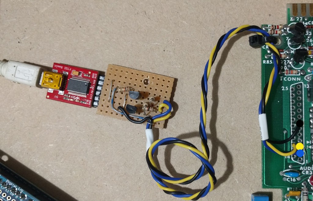
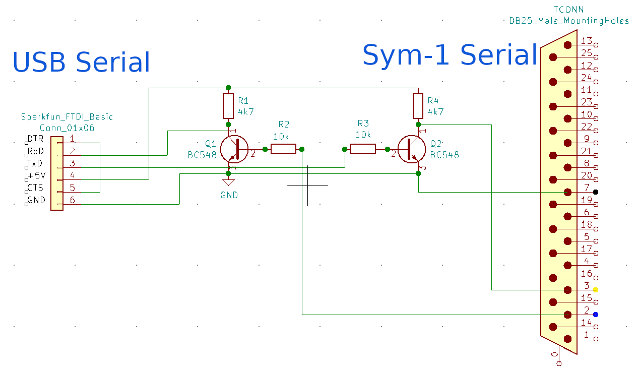
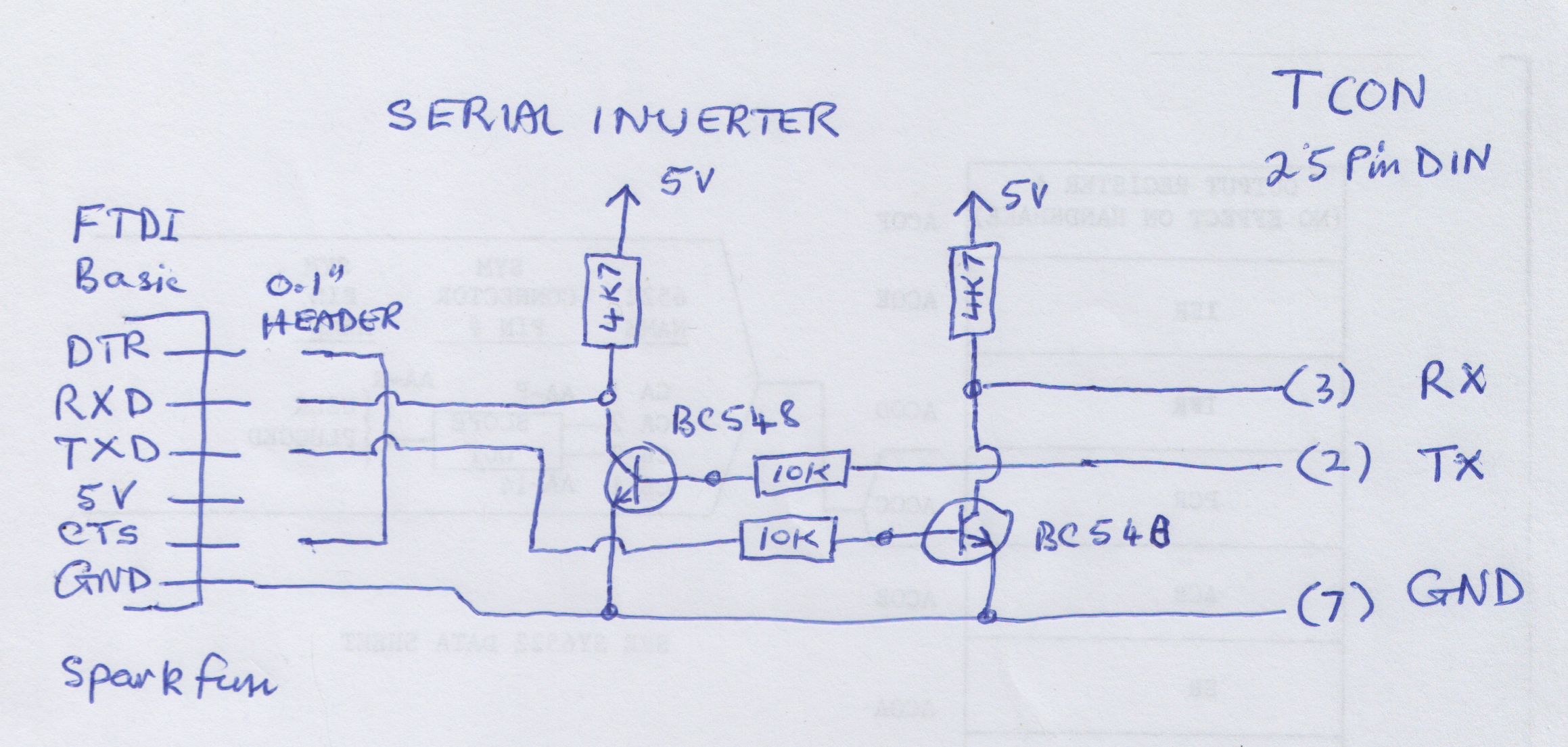
It seemed logical to bit-bang a full USB interface on the Sym-1 to drag it into the 21st century and so the wide number of terminal apps in today's modern operating systems could be used with it. Using a USB FTDI Basic from Sparkfun seemed the way to go and was connected up. This proved not to work. After a bit of multi-meter work it was determined the polarities of the data streams were inverted. So while the RS-232 assumed a "hi" signal was -15V, the 5V logic assumed it was something above 4.5V. So the Sym-1 understood 5V logic but the signal would be inverted. The FTDI board provided a 5V rail and a GND, and a couple of BC548's and four resistors were rigged (hacked?) up as inverters.
![]()
This proved to work. How is this known? Here is a printout of the Sym-1 boards response when a 'Q' is typed after a reset (plus there is a Beep from the piezo transducer).
![]()
The Sym-1 has a dual login option. If the Serial Port responds first it auto detects the Baud rate and continues to work with it. Alternatively the onboard keyboard has "CR" (carriage return), and this then would assume control. The "." is one of the most modest startup messages ever.
![]()
![]()
The Baud rate is determined by timing the first character typed and setting the Baud rate from that. In this case it is the character ASCII 'Q'. It is probably one of the most understated boot up messages of all time, the Sym-1 responded with the "." to indicate a successful negotiation of a serial connection. Extremely modest! However, as we shall see, this self effacing group of programmers were an inspired group and wanted their design to incorporate as many really useful features and not just "glam".
So if you have a retro SBC lying around and it says it has an RS-232 interface then you will probably need to reduce the voltage swings to a 0V-5V range to get it to work with a modern USB-FDTI interface, but also invert the signal polarity as well.
If you would really like to go down a retro computer rabbit hole, then look up "RS-232" pin-out...
Read more -
Sym-1 plus EPROM
09/23/2021 at 02:15 • 0 commentsOne of the popular chip formats in the 70's and 80's were the ubiquitous EPROMs (Electrically Programmable Read Only Memories). They had very good memory density at the time and were accessible technology for hackers and OEMs alike. They had the advantage of easy to program for a given EPROM and good value for money in density, plus they allowed the power of the CPU to boot in to managing its own hardware right from the get-go! This unleashed a myriad of designs that could utilise all sorts of hardware for input and output. While architecturally so much simpler than a CPU, they made a huge contribution to the development of the computer systems of today.
The challenge with EPROMs came after a while when different companies decided on different pin-outs, programming voltages and programming algorithms. If only one EPROM version was chosen, it was pretty easy to get up and going. However as bigger EPROMs became more available it was harder to keep moving up the food chain. The programmer designed here was originally built to read the ROMs that came with the Sym-1 I bought. I wanted to be able to archive them. I then wanted to use the ROM reader to become an EPROM programmer. EEPROMs were not all that easy to get hold over 4-5yrs ago when I began this project, though I can see the future is in their hands as well. For the moment though to go "full-retro" amd EPROM programmer was an easy nostalgic choice and I had another lovely Arduino Mega 2560 to help me out.
So the system outlined below simply lines up the Mega output ports into 8 bit blocks of the Address and Data line of the ROM chip. The set up below is for the 8kB 2716 EPROM, but could be easily modified by either changing the software on how the Address and Chip Select pins are used to cater for other devices. The Mega has plenty of power to get this moving along easily. At worst if you only want to try to program one it could easily be setup with a prototyping board and hook up wires. (the wires could be moved around to cater for different ROMs, but many of connections eg D0-D7 and A0-A7, would be OK).
Now for the huge hack! I was keen to use the 2716 EPROM, but it had some weird voltage requirements like lifting the Vcc from 5V to 5.6V during programming. Applying 12.5V for Vpp was reasonable, but the other requirements were just proving too hard. So I rigged up the programmer and simply hardwired a switch for the 12V. Ran the program and it worked. More info to follow!!!!
EPROM Programmer + SD card read/write
Arduino Mega 2560 plus USB-Tiny programmer
Now with iterative programming pulses
** SD card attached to SPI bus as follows:
** MOSI - pin 50
** MISO - pin 51
** CLK - pin 52
** CS - pin 53Connections to program the 8kB EPROMs, hence using 2764's ( 12.5V Vpp )
Port Mega
Pin#2764 Socket
ZIFSocket
ZIF2764 Mega
Pin#Port Vpp 1 28 Vcc K 12 A12 2 27 !PGM 15 K A 29 A7 3 26 Vcc A 28 A6 4 25 A8 8 K A 26 A5 5 24 A9 9 K A 27 A4 6 23 A11 11 K A 25 A3 7 22 !OE 13 K A 24 A2 8 21 A10 10 K A 23 A1 9 20 !CE 14 K A 22 A0 10 19 D7 37 C C 30 D0 11 18 D6 36 C C 31 D1 12 17 D5 35 C C 32 D2 13 16 D4 34 C 0V 0V 14 15 D3 33 C -
SYM-1 Memory Allocation
09/21/2021 at 04:25 • 0 commentsThe Sym-1 had a comprehensive expansion strategy with both I/O (3 6522 PIAs and a 6532 RIOT) and memory. The board was shipped with 1kB RAM and this could be expanded "on-board" to 8 2114 Static RAM chips to 4kB onboard. (It also allowed write protect of this extra RAM in 1kB blocks). There was also provided four 24pin ROM sockets. As shipped it had its monitor (Supermon 1.0) in a 4kB block from $8000 to $8FFF. The other three sockets were pre-wired to accept 2kB ROMs, or EPROMs.
To be able to do this configuration after shipping meant providing some ROM selection to be done in the factory but to also allow later configuration in the field. A system of address decoders (74LS145) were used that were open collector outputs and options to "OR" these together to be able to map ROMs from 2kB, 4kB and 8kB into the upper memory spaces. RAE and BASIC were both available as two 4kB ROMs or as single 8kB ROMs.
Here is an example memory map of the upper 32kB
$8000-8FFF SuperMon 4kB $9000-9FFF Supermon Expansion or Extensions 4kB $A000-AFFF Memory Mapped I/O and 128B of System RAM (Not usable as ROM) 4kB $B000-BFFF
$E000-EFFFResident Assembler and Editor (RAE)
(This has separated 4kB entries *, and note correction below )4kB
4kB$C000-DFFF Microsoft BASIC 8kB $F000-FFFF Extension area (must include ROM startup Vector) 4kB In the early 1980's the 2716 EPROM (2kB) was a popular and easy to use chip and was often used to expand the Sym-1 ROM memory. These days the 2764 EPROM (8kB) is about the same numerical price or cheaper in quantity, and of course much cheaper given inflation. However a 2764 has 28 pins and not 100% compatible with the 24pin onboard sockets, but a good proposition having 8kB capacity means RAE or BASIC or Supermon+extensions could fit into a single chip (and we could fill the upper 28kB with ROM if desired). The old 2364 masked ROMs had only 24 pins, but as soon as the EPROM version is chosen it has extra pins for program enable and provision of the programming voltage (eg 12.5V etc)To get around this a riser board was made that has a 24 pin plug below and a 28 pin DIL socket on top, with the leads routed to reproduce the pin-outs functionality of a 2364 masked ROM.
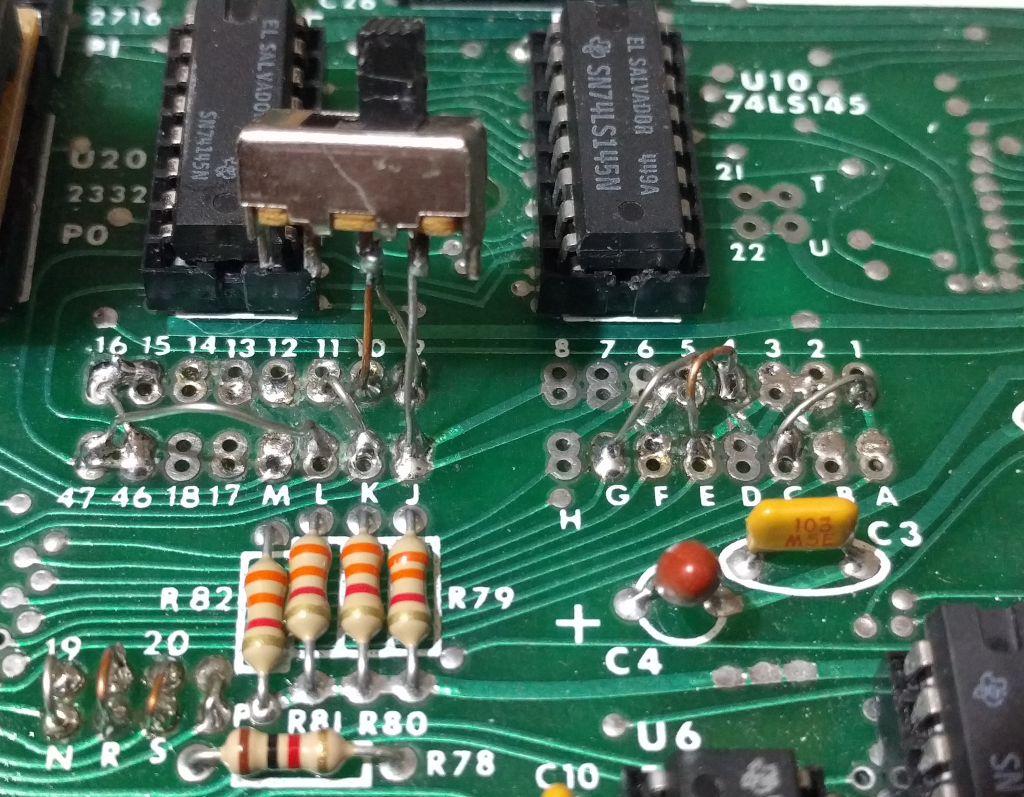
Because the pin-outs of a modern 2764 are about 85% identical to a 24pin 2364 only small changes needed to be made to re-route the various signals. This is outlined in another page here XXXXX. The trick after "burning" the EPROM is getting the memory map links set up so that the EPROM appears in the right memory locations. The information in the manual is very helpful and accurate, but organised that well to instantly make clear what needs to be done. Below is the array of connections (and PCB breaks) used to implement the system above.
![]()
The jumpers and PCB Breaks list:
C to 1 Allows RAE EPROM access to A11 ROM U22 E to 4 and G to 4 Allows Supermon +Extensions EPROM and
RAE Access to A12ROM U20 J to 10 and J to 9
(9&10 are switched to J)Adds CS for $9000 and $9800 Extensions ROM ROM U20 K to 11 CS for Extra ROM (not used here, eg BASIC at $C000) ROM U21 L to 46, L to 47,
L to 15 and L to 16CS for RAE EPROM, $B000-BFFF and $E000-EFFF ROM U22 Cut PCB at C // 2 disconnect S21 pin 18 from GND ROM U22 Cut PCB at E // 3 disconnect S02 pin 21 from GND ROM U20 Cut PCB at G // 5 or 6 disonnects S22 pin 21 from 5V ROM U22 This is essentially enabling the high address lines A11 and A12 for the bigger 8kB EPROMS and to also free the same lines from being tied to GND or 5V (for the original 2716 chip enable OE or CS pins).
* NB: RAE Addressing QUIRK There is a quirk in the Sym-1 ROM slots. Where A12 goes to the U20 Supermon chip correctly, there is a mistake for the U22 chip position that I chose for the RAE chip. It has the A12 line inverted. What this meant was I had to split the ROM image for RAE in half and reverse their position in the 8kB ROM. So $B000-BFFF was in the second half of the EPROM and $E000-EFFF...
Read more -
Sym-1 Memory Expansion
09/17/2021 at 04:36 • 0 commentsMemory was expensive in the days when the Sym-1 was released. The boards were shipped with 1kB of RAM (2 "2114" of 4bits by 1024), but could have another 6 of 2114s to be plugged in without any extra hardware required. The memory chips were not only expensive but the extra hardware of the PCB and sockets etc ramped up the price very quickly. I dutifully bought some 32kB Static RAM chips in 28pin DIL format and was setting about making a memory expansion board that could also accommodate 2764's to provide 8kB EPROM sockets, again 28DIL packages. I was half way through failing on this when I found this site Corsham Technologies where a full 64kB of RAM could be bought in a plug in and go format for the Sym-1 (and AIM and KIM). It could be paged in or out in 4kB blocks with a 16bit DIP switch, to work around where the SBC's existing RAM, ROMS or I/O were paged in. This was simply amazing!! I ordered one and it is the most highly recommended and easiest part of this project to complete. Just buy it, flick some DIP switches and plug it in. Bob Applegate has a fantastic design here. Using this I could soft load ROM images such as MS BASIC ($C000-DFFF) and RAE (Resident Assembler and Editor) ($B000-BFFF, $E000-$EFFF) into RAM and begin to feel I had a really worthwhile project on my hands.
![]()
This is the board attached to the expansion E-Connector (raw Address and data bus etc). The onboard 4kB of RAM is still plugged in and the expansion RAM is switched out of that range. I have used two sockets here back to back only because I had them. I originally wanted to build a back plane for my expansion boards to plug into. So I asked Bob not to solder the connector socket onto the board as he normally did. However when I thought it through, while I could flip the board over for a back plane insertion, unless it was also upside down, the connections were mirrored :-( So I soldered two plugs together as Gender Bender hack to preserve Bob's beautiful board, but still able to connect it up. Son't much around and follow Bob's full design and just buy with the socket soldered on.
Synertek used a Paper Tape format to store data to a 1" wide paper tape punch. These could be found on the side of ASR-33 Teletypes along with a paper tape reader. These machines were a hackers delight in the day, and were treasured. However they also ran at 300baud, or about 30 character a second, so the Synertek system was able to run at 300Baud, but sadly no faster. The format had a checksum at the end of each line and most likely while the 6502 can calculate and check the checksum at 300Baud, it could not cope if the baud rate was any higher. So when I got my expansion RAM and wrote a Python script to turn Binary images into Paper Tape format, and tried to load the paper tape versions 8kB ROM images from Sym Resources at http://6502.org/trainers/synertek/ I found the speed was really painful. The 300Baud was bad enough, but because each byte was sent as two hexadecimal charcters, it made it twice as hard to bear. The second problem was the GTK-Term program that had served well up until then could not stream that many characters as characters and would always stall mid load. The answer was to use the MiniTerm Serial program that is found in the Python suite. Here is the command to trigger it off
First of all install the following:
sudo apt-get install python-serial
and then begin the TTY session with:
python3 -m serial.tools.miniterm /dev/ttyUSB0 300
This did not stall on loading the Paper Tape files at 24,576 bytes long. (Nearly 3 times longer than the original ROM image!!!). Once the Python terminal was running and the Sym-1 prompt initialised at 300Baud (reset and press Q), LP could typed and it would be expecting the paper tape reader to begin feeding in the data. To get the Python terminal to send raw bytes from the <ROM>.ptape, CTRL-T was pressed and then CTRL-U, which prompted for the filename. Press...
Read more -
Sym-1 to R-Pi SBCs
09/17/2021 at 00:25 • 0 commentsHi fellow Hackers,
Every hacker's project published on Hackaday has some sort of back story, and a history of personal achievements and journeys. These are my personal reminiscences sparked off by the desire to revisit to the world of the Sym-1. You do not need to read this to follow the project, but it may answer questions like "Why on earth did he continue to use EPROMs etc etc", when you will see that old technology, grass roots stuff is deep within my psyche. If you have shared some similar experiences to me and want to read on, please do and enjoy the path travelled. First, rewind back to (c) 1976.....
National Semiconductor produced a neat little $75 Au kit to promote their SCMP processor. It was my first SBC and my struggles with minimal component and hardware supplies meant a lot of thinking went into very few bytes. It allowed me to use EPROMs, design a 6 wide multiplexed 7 seg display and a matrix 4x6 keyboard with a monitor squeezed into 256 bytes. By that time I could see the power of ROM controlled CPUs and I w3as looking for something bigger and better.
I left my research student position in Botany, not having achieved very much in my botanical endeavours and really keen to go teaching and use these new micro-controllers. The BASIC language was considered a nirvana, and desktop machines, ready built like the Commodore PET and the Apple II were being promoted. I could sense that these were not going to be good hacking machines, quite expensive and not much user I/O. The general hype around them pointed towards user software sales being most important, and please leave the hardware alone. I found this to be fundamentally counter to what I wanted, so I looked around and found the Synertek Sym-1.
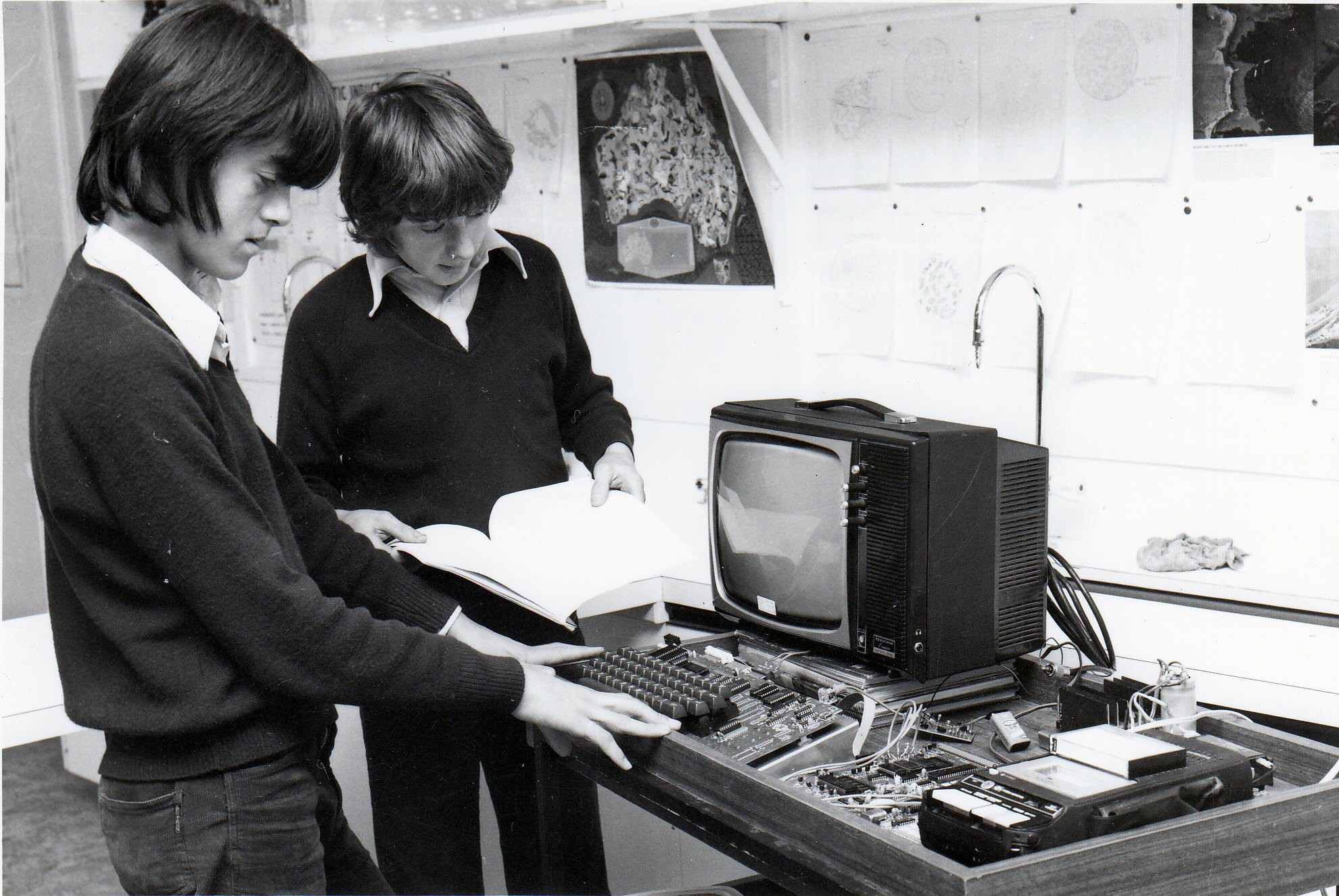
I found a dealer in Melbourne, put in for a Education Department Innovations Grant in 1979 and was successful with getting enough money (around $300) and local support to have the Year 9 students build a computer. I bought the Sym-1 and an 8kb Microsoft Basic in 2 ROMs. I bought a Sym-1 for myself soon after. The first thing we set out to do was build a huge power supply with a linear 309k 5V regulator and heat sink. It had to look impressive. We also bought a KTM-80 Synertek Video Terminal (I did not get one of these). This hooked up to a video display from an original Pong game we wrecked (I kept the main board until I lost track of it around 2007) and we had a functional computer running BASIC and the students had real hands on experience.
![]()
The above photo (c 1979) is two young lads, the one on the right is Lyndon Devalle, and the Sym-1 is shown hooked up to a Synertek KTM-80. The huge heat sink is just behind the Hitachi cassette deck. The 9volt battery was running the RF-modulator. Monitors were a rare breed and very expensive at the time.
For me though after a year or so it all went down hill as we came under increasing pressure to buy "hi-status" Apple II machines. The notion of a hardware system that allowed interfacing to the real world went out the window in my teaching until 2004. We eventually got some more money for an Apple II and it was all I dreaded. Kids pestering me to play Space Invaders and none those kids with an interest in how it actually worked.
I sourced an ASR-33 from somewhere and hooked it up to my Sym-1 at home rather than use a video terminal. I actually wrote school reports in BASIC on that thing. All upper-case and 10 char/in, yet nobody complained, I was seen as cutting edge!! Eventually I realised I needed a video screen and full ASCII keyboard. I designed a 64chr wide by 32 line "video card" in 7400 logic. I streamlined all the counting and displaying for simplicity of logic, but then had to ordered a custom crystal to run at the right speed to get the timing right. It duly arrived and I soldered it in and all of a sudden I had rock solid video. I designed the 8x8 character character in a 2kb EPROM and used a shared 2kb SRAM for the buffer. After that I built...
Read more -
SYM-1 to MEGA Connections
09/16/2021 at 09:45 • 0 commentsThe Sym-1 SBC has a short, but chequered history. The concepts that were built into the Super Mon 1.1 have subtly influenced the very well designed BBC Micro and laid the seeds for the ARM line of computers. Its major bottle neck though was not having a reliable filing system. The board originally was designed with an audio cassette tape system in mind for saving and loading files. This was a cost saving measure and a practical reality. Cassette recorders were vastly cheaper and more plentiful than Floppy Disc Drives.
Faced with the problem of reading the ancient literature (1975-1985) on what can be done with these boards, I decided to go about it in a different way and use the convenience of modern SBC's like and Arduino Mega 2560 to provide the storage system. To that end I used the Arduino Mega to provide an 8-bit parallel interface and enable reading and writing 8 bits at a time, regulated into and orderly fashion where the Sym-1 was the Master and doing hand shaking to regulate the data exchange between the two computers.
The germ of this idea came from Bob Applegate who publishes the web site Corsham Technologies. This amazing guy has developed fantastic hardware interfaces (and manufactured to the highest quality) that work with the KIM-1 mainly, but also has applications with the Sym-1 world as well. His 64Kb memory card is my mainstay. He also gave me the idea of piggy-backing onto a Mega2650 board to create a filing system. This paragraph is a somewhat belated acknowledgement, as I had lost the connection to his work for nearly a year and could not find my way back. Now, having found it on my phone, I have been reminded who inspired this work. It is a powerful idea and relies on on very little hardware bashing as the following diagram shows.
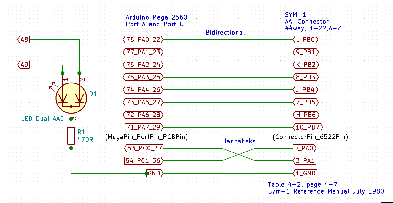
Here is the circuit diagram to carry out this exchange.
![]()
Very simple. The handshake lines were crossed over to make the hand shake algorithm as similar as possible on either side. The Sym-1 is the master and signals the Mega what data is to be exchanged. The mega has to respond with either sending the Sym-1 bytes, or is requested to listen to the Sym-1 for bytes. So the Mega simply waits to be "told" what to do. As long as the two systems stay in sync, then exchanges progress with next to no errors (thanks Bob!). Errors of data exchange are undetectable at the moment. Algorithm errors where the exchanges were not symmetrical were challenging to eliminate due to rusty skills with 6502 machine code. But that was what the challenge was all about.
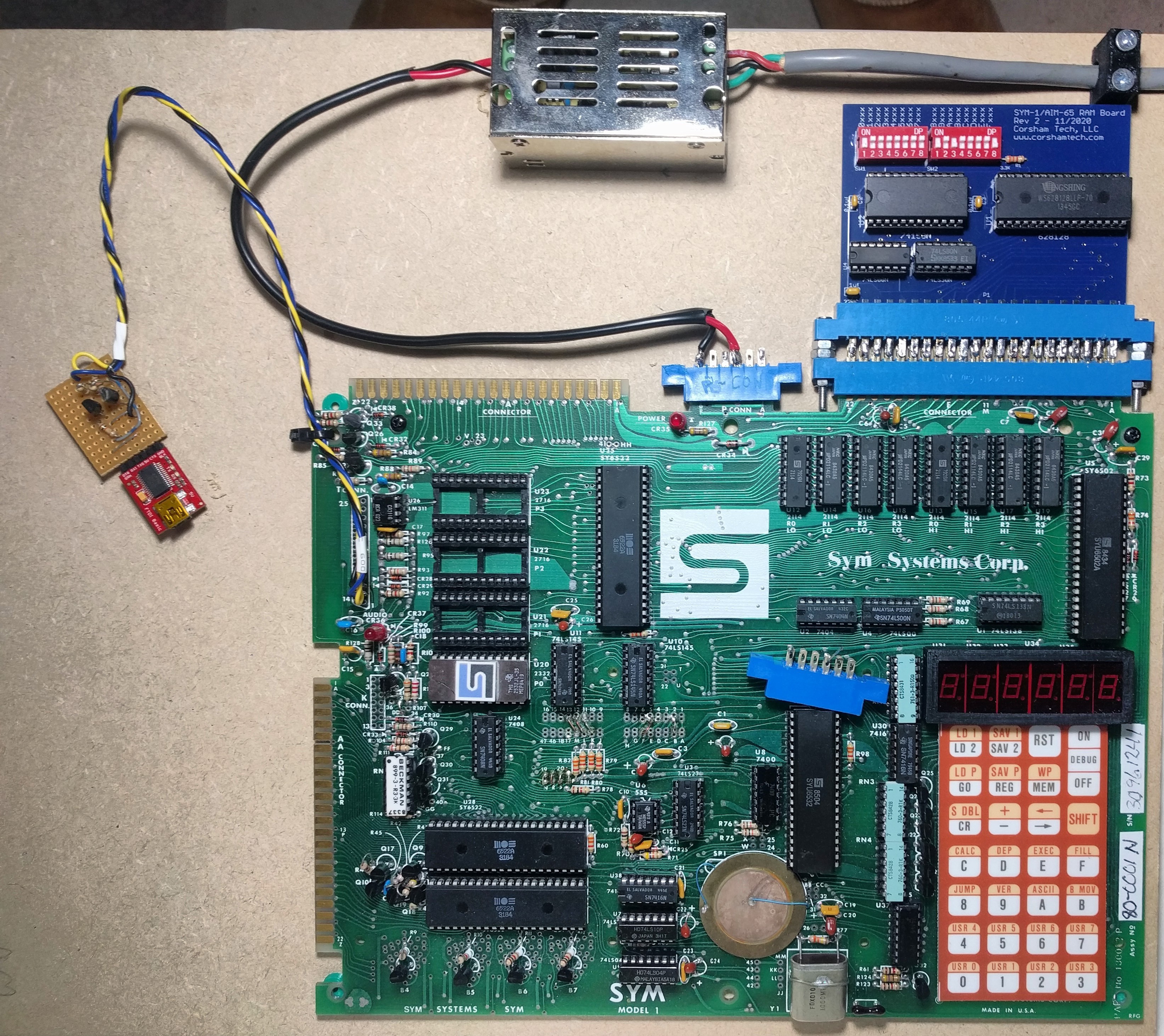
![]()
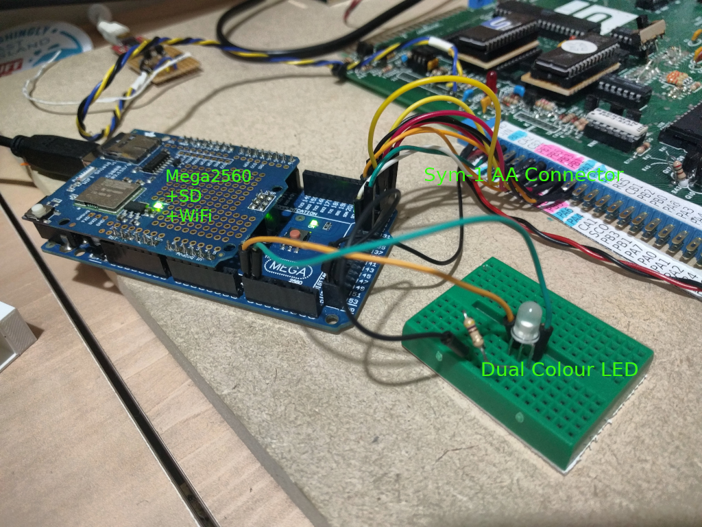
The dual colour LED shown in the photo connect to Mega pin 8 and 9, and they serve to alert the user of reads and write status, but most important of all, to also alert the user if the Mega starts up and finds the Sym-1 with any logic signals other than "handshake=null" to begin with. This is rectified when the MFS is started by the Sym-1 running the FS linking extensions at $9000, as it resets the Sym-1 handshake interface.
The speed of the exchange is quite fast, though I am waiting until I can do something like transfer an 8kB ROM image (Tested: well under 3 seconds), eg BASIC to RAM from the SD Card to get an estimate of the transfer rate. It is certainly an astronomic step from the cassette filing system days!!
For the project overview and support files Project Page Sym-1 A 6502 Phoenix!
-
SYM-1 Mega Filing System
09/16/2021 at 04:24 • 5 commentsThe Sym-1 was a SBC, built by Synertek from around 1979 when it started to become popular, and while the name does not roll off the tongue of people who become nostalgic about computers of this era, due to the quality of its design and build, it was a remarkably influential system. It, and its older brother, the KIM-1 from MOS Technology, attracted many very competent developers in the hacker community (well, even the Hollywood word NERD had just been invented by then, and of course, with 20-20 hindsight we can recognise these were genuine 100% Hackers at the time) who went on over time to develop a number of disk operating systems to free the Sym-1 from its native Audio Cassette interface.
The Sym-1 had a high-speed cassette interface and was quite reliable (well, as good as any cassette recorder could be, eg good brands such as Hitachi, were very reliable), but lacked the speed and indexed directory access of disc drives. Going over the literature around this time looking for clues on how to expand my Sym-1 board to this level of convenience, the articles are firmly set in the boundary where 8inch Floppy drives were being upstaged by 5.25inch Floppy drives. (Wikipedia: History of Floppy Drives) Having two floppy drives, one for system files and the other for data files was very fashionable. IDE Hard Drives with capacities around the 20-30Mbyte were also becoming available but were out of the price range for most hackers of the day. Never the less, the trend was becoming obvious. Full height Shugart SA800s would have to give way to the Shugart SA-400, and later, low profile half-height, double sided systems, such as made by Mitsubishi etc would ascend, and finally the 3.5inch rigid case, but floppy medium, would claim supremacy. However even back in 1980, it was easy to see the capacity plus speed of hard drives would win in the end.
So there are a couple of designs for IDE interfaces and DFSs for the Sym-1 and I have bought an IDE to SD-Card interface to maybe try to get one working. But for the moment the thought of recreating a full IDE interface was too daunting and not really meeting my aim to dabble back in the world of assembly language and bits/bytes at hard metal level.
An article that by Bob Applegate (of Corsham Technology) caught my eye during this research described using an Arduino and SD-Card combo to do a handshake parallel interface to a retro computer to enable saving, loading and managing files. I liked the statement that no error checking was built in as it was so reliable. It would be technically hard call for me to bit bash directly to an SD-Card, and the thought of trying to emulate any sort of MS-DOS was overwhelming. Though others have done this very successfully. Sadly Bob Applegate has passed away and so has his website. He was a true thinker of the golden years of the 6502 and only added to my conviction that I have never fully utlised any computer fully, before choosing to move on. We have been blessed to have so many riches to call on. Bob reminded me of so much that was possible and yet we just moved on, seduced by mega speeds and storage. The craftsmen (people?) who carved meticulously code from these devices with economy and frugality deserve our respect because they were true crafts-people, true thinkers, not just library abusers.
The Sym-1 was designed by Synertek and the Monitor program was 4kBytes and was big for its day (two to four times bigger than other evaluation board SBCs). The company also distributed a version of the 6502 Microsoft BASIC in a 8kByte ROM as well as a Resident Assembler and Editor (RAE) also in an 8kByte ROM. (Other languages such as Forth and Pascal were also mentioned, but not as well documented). These two main offerings were available in 2 by 4kB ROMs or a single 8kB ROM. After completing the 64kB RAM upgrade (again from Corsham Technology, see my other pages on this project) I was able to soft load both these images into Sym-1...
Read more